EP1065755A2 - Cover for an electrical connector - Google Patents
Cover for an electrical connector Download PDFInfo
- Publication number
- EP1065755A2 EP1065755A2 EP00304034A EP00304034A EP1065755A2 EP 1065755 A2 EP1065755 A2 EP 1065755A2 EP 00304034 A EP00304034 A EP 00304034A EP 00304034 A EP00304034 A EP 00304034A EP 1065755 A2 EP1065755 A2 EP 1065755A2
- Authority
- EP
- European Patent Office
- Prior art keywords
- cover
- housing
- centre
- arms
- latching
- Prior art date
- Legal status (The legal status is an assumption and is not a legal conclusion. Google has not performed a legal analysis and makes no representation as to the accuracy of the status listed.)
- Granted
Links
- 239000000463 material Substances 0.000 abstract description 4
- 230000007423 decrease Effects 0.000 abstract description 3
- 230000003247 decreasing effect Effects 0.000 abstract description 3
- 238000005452 bending Methods 0.000 description 2
- 238000000926 separation method Methods 0.000 description 2
- 238000000034 method Methods 0.000 description 1
Images

Classifications
-
- H—ELECTRICITY
- H01—ELECTRIC ELEMENTS
- H01R—ELECTRICALLY-CONDUCTIVE CONNECTIONS; STRUCTURAL ASSOCIATIONS OF A PLURALITY OF MUTUALLY-INSULATED ELECTRICAL CONNECTING ELEMENTS; COUPLING DEVICES; CURRENT COLLECTORS
- H01R13/00—Details of coupling devices of the kinds covered by groups H01R12/70 or H01R24/00 - H01R33/00
- H01R13/46—Bases; Cases
- H01R13/502—Bases; Cases composed of different pieces
- H01R13/506—Bases; Cases composed of different pieces assembled by snap action of the parts
-
- Y—GENERAL TAGGING OF NEW TECHNOLOGICAL DEVELOPMENTS; GENERAL TAGGING OF CROSS-SECTIONAL TECHNOLOGIES SPANNING OVER SEVERAL SECTIONS OF THE IPC; TECHNICAL SUBJECTS COVERED BY FORMER USPC CROSS-REFERENCE ART COLLECTIONS [XRACs] AND DIGESTS
- Y10—TECHNICAL SUBJECTS COVERED BY FORMER USPC
- Y10S—TECHNICAL SUBJECTS COVERED BY FORMER USPC CROSS-REFERENCE ART COLLECTIONS [XRACs] AND DIGESTS
- Y10S439/00—Electrical connectors
- Y10S439/901—Connector hood or shell
- Y10S439/902—Angularly disposed contact and conductor
Definitions
- the present invention relates to an electric connector provided with a cover.
- a conventional example of a connector provided with a cover is described in JP 10-112347.
- This connector comprises a housing and a cover. Terminal fittings are inserted into the housing, and electric wires which are fixed to the terminal fittings are guided outwards via an electric wire guiding face provided on a rear face of the housing.
- the cover is attached to the housing so as to cover the electric wire guiding face.
- the cover is block-like, one side thereof being joined to the housing by a hinge.
- the remaining three sides have resilient latching arms protruding therefrom. When the cover is attached to the housing, these latching arms engage with latching protrusions which protrude from the housing, these three arms latching the cover to the housing in an attached state.
- the cover is removed from the housing by bending the latching arms and separating them from the protrusions.
- a configuration is possible whereby the cover is a component separate from the housing and is not joined thereto by a hinge.
- the cover is inclined towards the housing with only a centre latching arm being in a bent state.
- a latching arm is located at each side of the centre arm. The inclining operation causes one of these two latching arms to separate from its protrusion.
- the cover is inclined in the opposite direction, thereby separating the other arm from its protrusion. In this manner, all three latching arms are separated from their respective protrusions, and the cover can be removed from the housing.
- the rigidity of the centre latching arm is desirable to decrease the rigidity of the centre latching arm so as to improve the ease with which it can be bent in a releasing direction. Furthermore, the rigidity of the side latching arms should be increased to deal with the case where an external force causes the electric wires to interfere with these side arms and thereby move them in the releasing direction.
- the present invention has been developed after taking the above problem into consideration, and aims to present a connector provided with a cover wherein the latch release operation of the centre arm is improved, and wherein the side arms are not released from their latched state as a result of interference from the electric wires.
- an electrical connector comprising a housing having an exit face for wires, and a cover for said exit face, the housing and cover having three mutually engageable resilient latching means, said latching means comprising a centre latching arm and two side latching arms, characterised in that said centre latching arm is a cantilever, and each of said side latching arms are joined along one side edge to a respective portion of one of said housing and cover, the other side edge being free.
- Such a cover/housing combination permits good flexibility of the centre arm, but allows the side arms to be rather stiff since they are not cantilevers.
- the side arms are provided on the cover and attached along one edge to a wall of the cover, substantially at right angles. This makes the side arms comparatively stiff.
- the centre arm preferably latches within the cover, in an aperture of the wall thereof.
- the cover is preferably symmetrical and the side arms identical but in mirror image.
- the centre arm may have an outwardly directed latching protrusion, whereas the side arms may have respective inwardly directed protrusions.
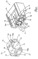
- a connector of the present embodiment is provided with a housing 10 made from plastic, and a cover 20.
- the housing 10 has a pair of left and right cavities 11, terminal fittings (not shown) being inserted from the posterior into these cavities 11.
- An electric wire 12 is joined to each terminal fitting passes through a rubber stopper 13, which is fitted to an opening of each cavity 11.
- the electric wire 12 extends to the exterior of the housing 10.
- a posterior end face of the housing 10 guides the electric wires 12 and in an approximately square electric wire guiding face 14.
- the cover 20 is attached to a posterior end portion of the housing 10 so as to cover the electric wire guiding face 14.
- the housing 10 is provided with a centre locking arm 15 and a left and right pair of locking protrusions 16 which serve to maintain the cover 20 in an attached state with the housing 10.
- the centre locking arm 15 is formed on an upper face of an outer circumference of a posterior end portion of the housing 10.
- This centre locking arm 15 has a cantilevered shape which protrudes in a posterior direction, and an upper face of a protruding end thereof has a locking protrusion 15A which protrudes beyond an outer face of the housing 10.
- Left and right side edges of the centre locking arm 15 do not join with other parts of the housing 10.
- a pair of slits 17 are formed between the left and right side edges of the centre locking arm 15 and the upper face of the outer circumference of the housing 10 so that the centre locking arm 15 remains separate. These slits 17 are provided in the upper face of the outer circumference of the housing 10 to the posterior, and bending spaces 18 are formed below the centre locking arm 15.
- the pair of locking protrusions 16 are formed at lower portions of left and right side faces of the outer circumference of the housing 10.
- the cover 20 is approximately square in shape and is attached to the posterior end portion of the housing 10 so as to cover the electric wire guiding face 14.
- the cover 20 fits with the exterior of the housing 10, and has a posterior wall 22 which protrudes towards the posterior. When the cover 20 is attached to the housing 10, this posterior wall 22 is opposite the electric wire guiding face 14.
- a central portion in a left-right direction of a lower face of the cover 20 has a cut-away 23 which is open at its anterior edge. Left and right edges and a posterior edge of the cut-away 23 extend downwards, and form a guiding member 24.
- An anterior face and a lower face of the cover 20 are open.
- the electric wires 12 which are guided outwards via the electric wire guiding face 14, are bent downwards within the cover 20 and are guided downwards to the exterior of the cover 20 from a lower face of the guiding member 24.
- the cover 20 is provided with a locking hole 25 and a left and right pair of side locking arms 26 as a means to maintain the cover 20 in an attached state with the housing 10.
- the locking hole 25 passes from an inner side to an outer side.
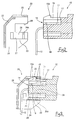
- the locking protrusion 15A of the centre locking arm 15 engages with the locking hole 25, thereby locking the cover 20.
- the locking protrusion 15A which is in the locking hole 25, is pressed, thereby causing the centre locking arm 15 to bend, and the lock is thereby released.
- the pair of side locking arms 26 are provided on left and right side faces of the cover 20, these side locking arms 26 consisting of a long and narrow portion of each side wall which extends in an anterior-posterior direction.
- a locking protrusion 26A is formed at an anterior end of each locking arm 26, these locking protrusions 26A protruding inwards from the inner circumference of the cover 20.
- a lower edge of each side locking arm 26 is unified with the lower half of the side walls of the cover 20 and approximately L-shaped circumference wails 27 which extend up to outer side edges of the lower face of the cover 20. Further, both posterior ends of theses L-shaped circumference walls 27 are joined by the posterior wall 22 of the cover 20. Lower edges of the circumference walls 27 join at approximately right angles with upper ends of the guiding member 24.
- Recessed grooves 28 are formed between upper ends of the side locking arms 26 and upper halves of the side walls of the cover 20, these recessed grooves 28 being open at the anterior end. As a result, the upper ends of the side locking arms 26 do not join with other parts of the cover 20.
- the cover 20 may be attached by pressing it onto the housing 10 from the posterior.
- the locking protrusion 15A of the centre locking arm 15 makes contact with the anterior end of the upper face of the cover 20, and is thereby bent downwards (towards the inner side).
- the locking protrusions 26A make contact with the locking protrusions 16 of the housing 10, and are thereby bent outwards.
- the centre locking arm 15 returns to its original position and the locking protrusions 15A thereof engages with the locking hole 25 of the cover 20.
- the side locking arms 26 return to their original position and the locking protrusions 26A thereof engage with the locking protrusions 16 of the housing 10.
- the electric wires 12 receive a pulling force from the side so as to press on the lower edge of the guiding member 24, this pulling force is transmitted via the guiding member 24 and the circumference walls 27, and acts as a force to bend the side locking arms 26 outwards (in a direction of separation from the locking protrusions 16).
- the lower edges of the side locking arms 26 are joined to the L-shaped circumference walls 27, and both circumference walls 27 are joined to the posterior wall 22. As a result, the rigidity thereof is increased and the side locking arms 26 are not bent in the lock separating direction.
- the electric wires 12 receive a pulling force from the posterior (a direction of separation from the electric wire guiding face 14) so as to press on the lower end of the posterior wall 22, this pulling force is transmitted via the posterior wall 22, the guiding member 24 and the circumference walls 27, and acts as a force to bend the side locking arms 26 towards the posterior of the locking protrusions 16.
- the lower edges of the side locking arms 26 are joined to the L-shaped circumference wall 27, and both circumference walls 27 are joined to the posterior wall 22. As a result, the rigidity thereof is increased, and the side locking arms 26 are not released from their latched state.
- the cover 20 is separated from the housing 10 by pressing the protrusion 15A which is in the locking hole 25, with a jig (not shown).
- the centre locking arm 15 is bent towards the interior, and the latch between the centre arm 15 and the hole 25 is released.
- the cover 20 is inclined to the left or the right (as seen from above), so as to pull either the left or right side wall towards the posterior.
- the left and right side walls widen, and one of the side locking arms 26 separates from its locking protrusion 16.
- the cover 20 is inclined in the opposite direction and the other side locking arm 26 separates from it locking protrusion 16. By this means, all of the arms 15 and 26 are released.
- the cover 20 may be separated from the housing 10 by pulling it towards the posterior.
- the centre locking arm 15 has a reduced rigidity and consequently the lock-release operation thereof is improved.
- the side locking arms 26 have an increased rigidity, and consequently they are not released from their locked state as a result of interference from the electric wires 12.
- the centre locking arm 15 and the side locking arms 26 are formed on mutually opposing components (the centre locking arm 15 being formed on the housing 10, and the side locking arms 26 being formed on the cover 20).
- changing the materials from which the housing 10 and the cover 20 are formed can reduce the rigidity of the centre locking arm 15 and increase the rigidity of the side locking arms 26.
- the lock-release operation of the centre locking arm 15 is improved, and the side locking arms 26 are not released from their locked state as a result of interference from the electric wires 12.
- the materials from which the housing 10 and the cover 20 are formed can be specified so as to confirm to the strength required of the housing 10 and the cover 20, to the protruding length, thickness, and width of the centre locking arm 15, and to the rigidity required thereof, and to conform to the protruding length, thickness of the side locking arms 26, to the thickness, dimensions in the circumference direction, and shape of the circumference walls, and to the rigidity required of the side locking arms 26, etc.
Landscapes
- Details Of Connecting Devices For Male And Female Coupling (AREA)
Abstract
Description
Claims (11)
- An electrical connector comprising a housing (10) having an exit face (14) for wires, and a cover (20) for said exit face (14), the housing (10) and cover (20) having three mutually engageable resilient latching means (15,26), said latching means comprising a centre latching arm (15) and two side latching arms (26), characterised in that said centre latching arm (15) is a cantilever, and each of said side latching arms (26) are joined along one side edge to a respective portion of one of said housing (10) and cover (20), the other side edge being free.
- A connector according to claim 1 wherein said side latching arms (26) are provided on said cover (20), each side latching arm (26) joining a respective wall (27) of said cover (20) along said one side edge substantially at a right angle.
- A connector according to claim 2 wherein the walls (27) associated with said one side edges are joined via an end face (22) of said cover (20), said end face (22) lying over said exit face (14) in use.
- A connector according to claim 3 wherein said side latching arms (26) have respective inwardly directed protrusions (26A) for engagement with a respective abutment (16) of said housing (10).
- A connector according to claim 4 wherein said side latching arms (26) are identical in mirror image.
- A connector according to any preceding claim wherein said centre latching arm (15) is provided on said housing (10).
- A connector according to claim 6 wherein said centre latching arm (15) enters within said cover (20) in use.
- A connector according to claim 7 wherein a protrusion (15A) of said centre latching arm (15) is engageable in an aperture (25) in the wall of said cover (20).
- A connector according to claim 8 wherein said cover (20) includes a wire exit opening opposite said aperture (25).
- A connector according to any preceding claim wherein said cover (20) is symmetrical.
- An electrical connector comprising a housing (10) having an exit face (14) for wires, and a cover (20) for said exit face (14), the housing (10) and cover (20) having three mutually engeagable resilient latching means (15,26), said latching means comprising a centre latching arm (15) and two side latching arms (26), characterised in that said centre latching arm (15) is on one of the housing (10) and cover (20) and said side latching arms (26) are on the other of said housing (10) and cover (20).
Applications Claiming Priority (2)
| Application Number | Priority Date | Filing Date | Title |
|---|---|---|---|
| JP18557799A JP3337008B2 (en) | 1999-06-30 | 1999-06-30 | connector |
| JP18557799 | 1999-06-30 |
Publications (3)
| Publication Number | Publication Date |
|---|---|
| EP1065755A2 true EP1065755A2 (en) | 2001-01-03 |
| EP1065755A3 EP1065755A3 (en) | 2003-07-02 |
| EP1065755B1 EP1065755B1 (en) | 2004-09-08 |
Family
ID=16173256
Family Applications (1)
| Application Number | Title | Priority Date | Filing Date |
|---|---|---|---|
| EP00304034A Expired - Lifetime EP1065755B1 (en) | 1999-06-30 | 2000-05-12 | Cover for an electrical connector |
Country Status (4)
| Country | Link |
|---|---|
| US (1) | US6478608B1 (en) |
| EP (1) | EP1065755B1 (en) |
| JP (1) | JP3337008B2 (en) |
| DE (1) | DE60013506T2 (en) |
Cited By (1)
| Publication number | Priority date | Publication date | Assignee | Title |
|---|---|---|---|---|
| WO2014184283A1 (en) * | 2013-05-17 | 2014-11-20 | Delphi International Operations Luxembourg S.À R.L. | Connector for motor vehicles |
Families Citing this family (15)
| Publication number | Priority date | Publication date | Assignee | Title |
|---|---|---|---|---|
| USD511500S1 (en) | 2004-05-04 | 2005-11-15 | Scientific-Atlanta, Inc. | Ground wire connection portion |
| US6969279B1 (en) * | 2004-05-04 | 2005-11-29 | Scientific-Atlanta, Inc. | Exterior connection weather seal |
| USD536670S1 (en) | 2004-05-04 | 2007-02-13 | Scientific-Atlanta, Inc. | Housing assembly with connection shroud |
| TWM274664U (en) * | 2004-10-10 | 2005-09-01 | Depo Auto Parts Ind Co Ltd | Contact structure of vehicle lamp |
| US7014498B1 (en) * | 2005-05-09 | 2006-03-21 | Lear Corporation | Safety closure for connectors with pivoting cover |
| JP4558619B2 (en) * | 2005-09-30 | 2010-10-06 | 矢崎総業株式会社 | connector |
| JP5598384B2 (en) * | 2011-03-04 | 2014-10-01 | 住友電装株式会社 | connector |
| DE112013007546T5 (en) * | 2013-10-31 | 2016-07-21 | Yazaki Corporation | Waterproof connector |
| JP6515824B2 (en) * | 2016-01-15 | 2019-05-22 | 住友電装株式会社 | connector |
| JP6840583B2 (en) * | 2017-03-16 | 2021-03-10 | モレックス エルエルシー | Connector assembly and connector cover |
| JP6916995B2 (en) * | 2018-01-31 | 2021-08-11 | 住友電装株式会社 | Wire cover and connector |
| CN109546438B (en) * | 2018-11-29 | 2020-01-14 | 安徽江淮汽车集团股份有限公司 | Automobile wire harness plug-in |
| EP3920340B1 (en) * | 2020-06-04 | 2025-10-29 | Rosenberger Hochfrequenztechnik GmbH & Co. KG | Activation clip |
| JP7428973B2 (en) * | 2020-09-28 | 2024-02-07 | 住友電装株式会社 | connector |
| CN114992153A (en) * | 2022-05-09 | 2022-09-02 | 惠州市三创科技有限公司 | Fan frame |
Family Cites Families (9)
| Publication number | Priority date | Publication date | Assignee | Title |
|---|---|---|---|---|
| DE3600025A1 (en) * | 1985-01-07 | 1986-07-10 | Amp Inc., Harrisburg, Pa. | Multipole plug connector |
| US5295859A (en) * | 1991-10-23 | 1994-03-22 | Hirose Electric Co., Ltd. | Electric connector |
| US5271739A (en) * | 1992-11-06 | 1993-12-21 | The Whitaker Corporation | System for attaching wire shield to plug |
| JP2916572B2 (en) * | 1994-04-15 | 1999-07-05 | 矢崎総業株式会社 | Method for fixing packing of waterproof connector and its structure |
| JPH09180817A (en) * | 1995-12-27 | 1997-07-11 | Yazaki Corp | Connector structure |
| US5820401A (en) * | 1996-03-29 | 1998-10-13 | The Whitaker Corporation | Wire guide assembly for use with an electrical connector having a jack screw |
| JPH10112347A (en) * | 1996-10-07 | 1998-04-28 | Sumitomo Wiring Syst Ltd | connector |
| US5921806A (en) * | 1997-10-30 | 1999-07-13 | The Whitaker Corporation | Multi-exit strain relief for an electrical connector |
| JP3449912B2 (en) * | 1998-03-10 | 2003-09-22 | 矢崎総業株式会社 | connector |
-
1999
- 1999-06-30 JP JP18557799A patent/JP3337008B2/en not_active Expired - Fee Related
-
2000
- 2000-05-12 DE DE60013506T patent/DE60013506T2/en not_active Expired - Lifetime
- 2000-05-12 EP EP00304034A patent/EP1065755B1/en not_active Expired - Lifetime
- 2000-05-26 US US09/579,018 patent/US6478608B1/en not_active Expired - Fee Related
Cited By (4)
| Publication number | Priority date | Publication date | Assignee | Title |
|---|---|---|---|---|
| WO2014184283A1 (en) * | 2013-05-17 | 2014-11-20 | Delphi International Operations Luxembourg S.À R.L. | Connector for motor vehicles |
| FR3005796A1 (en) * | 2013-05-17 | 2014-11-21 | Delphi Int Operations Luxembourg Sarl | CONNECTOR FOR MOTOR VEHICLES |
| CN105393410A (en) * | 2013-05-17 | 2016-03-09 | 德尔福国际业务卢森堡公司 | Connector for motor vehicles |
| CN105393410B (en) * | 2013-05-17 | 2018-07-03 | 德尔福国际业务卢森堡公司 | The connector of motor vehicle |
Also Published As
| Publication number | Publication date |
|---|---|
| EP1065755A3 (en) | 2003-07-02 |
| DE60013506D1 (en) | 2004-10-14 |
| US6478608B1 (en) | 2002-11-12 |
| DE60013506T2 (en) | 2005-09-15 |
| EP1065755B1 (en) | 2004-09-08 |
| JP3337008B2 (en) | 2002-10-21 |
| JP2001015207A (en) | 2001-01-19 |
Similar Documents
| Publication | Publication Date | Title |
|---|---|---|
| EP1065755B1 (en) | Cover for an electrical connector | |
| US5401179A (en) | Locking mechanism for a connector assembly of low engaging/disengaging force type | |
| US6231398B1 (en) | Connector with upper and lower inner housing members | |
| JP2888925B2 (en) | Connector structure provided with latch means | |
| US6354860B1 (en) | Connector and connector assembly | |
| JP3074644U (en) | Electrical connector with improved latching mechanism | |
| US6176745B1 (en) | Pressure contact connector | |
| JP3083070B2 (en) | Double locking connector | |
| JPH07114134B2 (en) | Connector with terminal locking device | |
| JPH0329276A (en) | Terminal locking piece for electric connector | |
| JP2000231961A (en) | connector | |
| US6321446B1 (en) | Method of fitting connectors and the connectors for use in the method | |
| EP0698944B1 (en) | Electrical connector with hinged cover | |
| JP2017216057A (en) | connector | |
| JP2500134B2 (en) | Electrical connector | |
| US5160279A (en) | Double lock connector | |
| JPH11297420A (en) | connector | |
| KR20240076679A (en) | Connector | |
| US5269699A (en) | Lockable electrical connector assembly | |
| JPH09245869A (en) | Connector with terminal lock | |
| JP3283791B2 (en) | Connector and connector manufacturing method | |
| EP1220365B1 (en) | Divided connector | |
| JP3774635B2 (en) | Electrical connector with cover case | |
| US5895285A (en) | Press-contact type connector | |
| JPH06197432A (en) | Electrical connection box |
Legal Events
| Date | Code | Title | Description |
|---|---|---|---|
| PUAI | Public reference made under article 153(3) epc to a published international application that has entered the european phase |
Free format text: ORIGINAL CODE: 0009012 |
|
| 17P | Request for examination filed |
Effective date: 20000525 |
|
| AK | Designated contracting states |
Kind code of ref document: A2 Designated state(s): AT BE CH CY DE DK ES FI FR GB GR IE IT LI LU MC NL PT SE |
|
| AX | Request for extension of the european patent |
Free format text: AL;LT;LV;MK;RO;SI |
|
| PUAL | Search report despatched |
Free format text: ORIGINAL CODE: 0009013 |
|
| AK | Designated contracting states |
Designated state(s): AT BE CH CY DE DK ES FI FR GB GR IE IT LI LU MC NL PT SE |
|
| AX | Request for extension of the european patent |
Extension state: AL LT LV MK RO SI |
|
| 17Q | First examination report despatched |
Effective date: 20030912 |
|
| GRAP | Despatch of communication of intention to grant a patent |
Free format text: ORIGINAL CODE: EPIDOSNIGR1 |
|
| AKX | Designation fees paid |
Designated state(s): DE FR GB IT |
|
| GRAS | Grant fee paid |
Free format text: ORIGINAL CODE: EPIDOSNIGR3 |
|
| GRAA | (expected) grant |
Free format text: ORIGINAL CODE: 0009210 |
|
| AK | Designated contracting states |
Kind code of ref document: B1 Designated state(s): DE FR GB IT |
|
| PG25 | Lapsed in a contracting state [announced via postgrant information from national office to epo] |
Ref country code: IT Free format text: LAPSE BECAUSE OF FAILURE TO SUBMIT A TRANSLATION OF THE DESCRIPTION OR TO PAY THE FEE WITHIN THE PRE;WARNING: LAPSES OF ITALIAN PATENTS WITH EFFECTIVE DATE BEFORE 2007 MAY HAVE OCCURRED AT ANY TIME BEFORE 2007. THE CORRECT EFFECTIVE DATE MAY BE DIFFERENT FROM THE ONE RECORDED.SCRIBED TIME-LIMIT Effective date: 20040908 |
|
| REG | Reference to a national code |
Ref country code: GB Ref legal event code: FG4D |
|
| REG | Reference to a national code |
Ref country code: IE Ref legal event code: FG4D |
|
| REF | Corresponds to: |
Ref document number: 60013506 Country of ref document: DE Date of ref document: 20041014 Kind code of ref document: P |
|
| PG25 | Lapsed in a contracting state [announced via postgrant information from national office to epo] |
Ref country code: GB Free format text: LAPSE BECAUSE OF NON-PAYMENT OF DUE FEES Effective date: 20050512 |
|
| ET | Fr: translation filed | ||
| PLBE | No opposition filed within time limit |
Free format text: ORIGINAL CODE: 0009261 |
|
| STAA | Information on the status of an ep patent application or granted ep patent |
Free format text: STATUS: NO OPPOSITION FILED WITHIN TIME LIMIT |
|
| 26N | No opposition filed |
Effective date: 20050609 |
|
| GBPC | Gb: european patent ceased through non-payment of renewal fee |
Effective date: 20050512 |
|
| PGFP | Annual fee paid to national office [announced via postgrant information from national office to epo] |
Ref country code: DE Payment date: 20120510 Year of fee payment: 13 |
|
| PGFP | Annual fee paid to national office [announced via postgrant information from national office to epo] |
Ref country code: FR Payment date: 20120608 Year of fee payment: 13 |
|
| PG25 | Lapsed in a contracting state [announced via postgrant information from national office to epo] |
Ref country code: DE Free format text: LAPSE BECAUSE OF NON-PAYMENT OF DUE FEES Effective date: 20131203 |
|
| REG | Reference to a national code |
Ref country code: FR Ref legal event code: ST Effective date: 20140131 |
|
| REG | Reference to a national code |
Ref country code: DE Ref legal event code: R119 Ref document number: 60013506 Country of ref document: DE Effective date: 20131203 |
|
| PG25 | Lapsed in a contracting state [announced via postgrant information from national office to epo] |
Ref country code: FR Free format text: LAPSE BECAUSE OF NON-PAYMENT OF DUE FEES Effective date: 20130531 |