EP1065740A2 - Flexible method for monitoring fuel cell voltage - Google Patents
Flexible method for monitoring fuel cell voltage Download PDFInfo
- Publication number
- EP1065740A2 EP1065740A2 EP00110375A EP00110375A EP1065740A2 EP 1065740 A2 EP1065740 A2 EP 1065740A2 EP 00110375 A EP00110375 A EP 00110375A EP 00110375 A EP00110375 A EP 00110375A EP 1065740 A2 EP1065740 A2 EP 1065740A2
- Authority
- EP
- European Patent Office
- Prior art keywords
- cells
- cluster
- voltage
- fuel
- fuel cell
- Prior art date
- Legal status (The legal status is an assumption and is not a legal conclusion. Google has not performed a legal analysis and makes no representation as to the accuracy of the status listed.)
- Withdrawn
Links
Images


Classifications
-
- H—ELECTRICITY
- H01—ELECTRIC ELEMENTS
- H01M—PROCESSES OR MEANS, e.g. BATTERIES, FOR THE DIRECT CONVERSION OF CHEMICAL ENERGY INTO ELECTRICAL ENERGY
- H01M8/00—Fuel cells; Manufacture thereof
- H01M8/04—Auxiliary arrangements, e.g. for control of pressure or for circulation of fluids
- H01M8/04298—Processes for controlling fuel cells or fuel cell systems
- H01M8/04313—Processes for controlling fuel cells or fuel cell systems characterised by the detection or assessment of variables; characterised by the detection or assessment of failure or abnormal function
- H01M8/04537—Electric variables
- H01M8/04544—Voltage
- H01M8/04552—Voltage of the individual fuel cell
-
- G—PHYSICS
- G01—MEASURING; TESTING
- G01R—MEASURING ELECTRIC VARIABLES; MEASURING MAGNETIC VARIABLES
- G01R31/00—Arrangements for testing electric properties; Arrangements for locating electric faults; Arrangements for electrical testing characterised by what is being tested not provided for elsewhere
- G01R31/36—Arrangements for testing, measuring or monitoring the electrical condition of accumulators or electric batteries, e.g. capacity or state of charge [SoC]
- G01R31/3644—Constructional arrangements
- G01R31/3648—Constructional arrangements comprising digital calculation means, e.g. for performing an algorithm
-
- G—PHYSICS
- G01—MEASURING; TESTING
- G01R—MEASURING ELECTRIC VARIABLES; MEASURING MAGNETIC VARIABLES
- G01R31/00—Arrangements for testing electric properties; Arrangements for locating electric faults; Arrangements for electrical testing characterised by what is being tested not provided for elsewhere
- G01R31/36—Arrangements for testing, measuring or monitoring the electrical condition of accumulators or electric batteries, e.g. capacity or state of charge [SoC]
- G01R31/382—Arrangements for monitoring battery or accumulator variables, e.g. SoC
- G01R31/3835—Arrangements for monitoring battery or accumulator variables, e.g. SoC involving only voltage measurements
-
- G—PHYSICS
- G01—MEASURING; TESTING
- G01R—MEASURING ELECTRIC VARIABLES; MEASURING MAGNETIC VARIABLES
- G01R31/00—Arrangements for testing electric properties; Arrangements for locating electric faults; Arrangements for electrical testing characterised by what is being tested not provided for elsewhere
- G01R31/36—Arrangements for testing, measuring or monitoring the electrical condition of accumulators or electric batteries, e.g. capacity or state of charge [SoC]
- G01R31/396—Acquisition or processing of data for testing or for monitoring individual cells or groups of cells within a battery
-
- H—ELECTRICITY
- H01—ELECTRIC ELEMENTS
- H01M—PROCESSES OR MEANS, e.g. BATTERIES, FOR THE DIRECT CONVERSION OF CHEMICAL ENERGY INTO ELECTRICAL ENERGY
- H01M8/00—Fuel cells; Manufacture thereof
- H01M8/04—Auxiliary arrangements, e.g. for control of pressure or for circulation of fluids
- H01M8/04298—Processes for controlling fuel cells or fuel cell systems
- H01M8/04313—Processes for controlling fuel cells or fuel cell systems characterised by the detection or assessment of variables; characterised by the detection or assessment of failure or abnormal function
- H01M8/04537—Electric variables
- H01M8/04544—Voltage
- H01M8/04559—Voltage of fuel cell stacks
-
- G—PHYSICS
- G01—MEASURING; TESTING
- G01R—MEASURING ELECTRIC VARIABLES; MEASURING MAGNETIC VARIABLES
- G01R31/00—Arrangements for testing electric properties; Arrangements for locating electric faults; Arrangements for electrical testing characterised by what is being tested not provided for elsewhere
- G01R31/005—Testing of electric installations on transport means
- G01R31/006—Testing of electric installations on transport means on road vehicles, e.g. automobiles or trucks
-
- Y—GENERAL TAGGING OF NEW TECHNOLOGICAL DEVELOPMENTS; GENERAL TAGGING OF CROSS-SECTIONAL TECHNOLOGIES SPANNING OVER SEVERAL SECTIONS OF THE IPC; TECHNICAL SUBJECTS COVERED BY FORMER USPC CROSS-REFERENCE ART COLLECTIONS [XRACs] AND DIGESTS
- Y02—TECHNOLOGIES OR APPLICATIONS FOR MITIGATION OR ADAPTATION AGAINST CLIMATE CHANGE
- Y02E—REDUCTION OF GREENHOUSE GAS [GHG] EMISSIONS, RELATED TO ENERGY GENERATION, TRANSMISSION OR DISTRIBUTION
- Y02E60/00—Enabling technologies; Technologies with a potential or indirect contribution to GHG emissions mitigation
- Y02E60/30—Hydrogen technology
- Y02E60/50—Fuel cells
Definitions
- This invention relates to a fuel cell system, and more particularly to a system having a plurality of cells which consume an H 2 -rich gas to produce power for vehicle propulsion.
- Fuel cells have been used as a power source in many applications. Fuel cells have also been proposed for use in electrical vehicular power plants to replace internal combustion engines. In proton exchange membrane (PEM) type fuel cells, hydrogen is supplied to the anode of the fuel cell and air is supplied as the oxidant to the cathode.
- PEM fuel cells include a "membrane electrode assembly" (MEA) comprising a thin, proton transmissive, solid polymer membrane-electrolyte having the anode on one of its faces and the cathode on the opposite face.
- MEA membrane electrode assembly
- the MEA is sandwiched between a pair of electrically conductive elements which (1) serve as current collectors for the anode and cathode, and (2) contain appropriate channels and/or openings therein for distribution the fuel cell's gaseous reactants over the surfaces of the respective anode and cathode catalysts.
- a plurality of individual cells are commonly bundled together to form a PEM fuel cell stack.
- the term fuel cell is typically used to refer to either a single cell or a plurality of cells (stack) depending on the context.
- a group of cells within the stack, typically adjacent cells, is referred to as a cluster.
- hydrogen (H 2 ) is the anode reactant (i.e., fuel) and oxygen is the cathode reactant (i.e., oxidant).
- the oxygen can be either a pure form (O 2 ), or air (a mixture of O 2 and N 2 ).
- the solid polymer electrolytes are typically made from ion exchange resins such as perfluoronated sulfonic acid.
- the anode/cathode typically comprises finely divided catalytic particles, which are often supported on carbon particles, and admixed with a proton conductive resin.
- the catalytic particles are typically costly precious metal particles.
- liquid fuel such as an alcohol (e.g., methanol or ethanol), or hydrocarbons (e.g., gasoline) as the source of hydrogen for the fuel cell.
- alcohol e.g., methanol or ethanol
- hydrocarbons e.g., gasoline
- Such liquid fuels for the vehicle are easy to store onboard and there is a nationwide infrastructure for supplying liquid fuels.
- fuels must be dissociated to release the hydrogen content thereof for fueling the fuel cell.
- the dissociation reaction is accomplished heterogeneously within a chemical fuel processor, known as a reformer, that provides thermal energy throughout a catalyst mass and yields a reformate gas comprising primarily hydrogen and carbon dioxide.
- methanol and water are ideally reacted to generate hydrogen and carbon dioxide according to this reaction: CH 3 OH+H 2 O ⁇ CO 2 +3H 2 .
- the reforming reaction is an endothermic reaction that requires external heat for the reaction to occur.
- Fuel cell systems which process a hydrocarbon fuel to produce a hydrogen-rich reformate for consumption by PEM fuel cells are known and are described in co-pending United States Patent Application Serial Nos. 08/975,442 and 08/980,087, filed in the name of William Pettit in November, 1997, and U.S. Serial No. 09/187,125, filed November 5, 1998, and each assigned to the assignee of the present invention.
- a typical PEM fuel cell and its membrane electrode assembly (MEA) are described in United States Patent Nos. 5,272,017 and 5,316,871, issued respectively December 21, 1993 and May 31, 1994, each assigned to the assignee of the present invention.
- the reaction within the fuel cell must be carried out under conditions which preserve the integrity of the cell and its valuable polymeric and precious metal catalyst components. Since the anode, cathode and electrolyte layers of the MEA assembly are each formed of polymers, it is evident that such polymers may be softened, melted or degraded if exposed to too high a temperature.
- a typical fuel cell system does not directly monitor the rate of hydrogen flow to the fuel cell; that is, a hydrogen sensor is not located directly upstream of the fuel cell. In such a fuel cell system, it is important to match the load being demanded of the fuel cell with the rate at which hydrogen is supplied to the fuel cell. If more current is attempted to be drawn out of the fuel cell than the fuel cell is capable of supplying because there is not enough hydrogen to create the increased electrical power, then it is possible to significantly degrade the fuel cell stack.
- a cell begins acting as a resistor and will start heating up. As the cell continues to heat up, it will adversely affect the cell next to it and, if heat effect is not abated, it is possible to melt components of the fuel cell.
- the fuel cell stack might have, for example, 200 cells at 0.7 to 0.8 volts each at a given load.
- the overall fuel stack voltage changes from 150 volts to 147.75 volts. This latter value is well above the expected voltage if all of the cells were at 0.7 volts, that is, at the lower range indicating a stack voltage of 140 volts which is nominally acceptable.
- a typical approach relies on monitoring groups of cells, referred to as "clusters" instead each individual cell. Care must be taken not to group too many cells together in a cluster since the total contribution of each cell's output to the chosen cluster output must be large enough so that an individual poor performing cell can be resolved from the condition where are cells in the cluster are on the low side of nominal performance. This resolution limitation usually results in either three or four cells being grouped together in a cluster.
- the stack when forcing a cluster monitoring requirement on the fuel cell stack design, the result is that the stack must be designed with a total number of cells which have a numerical modulus equal to the number of cells in each monitored cluster in order not to leave any cell(s) unmonitored. This poses a problem when there is a need to change the number of cells in a cluster for a given stack design. Additionally, adding "extra" cells to a new fuel cell design just to make the number of cells convenient for the monitoring system is not considered a good economic practice.
- the present invention is a method of monitoring a fuel cell apparatus wherein a hydrogen-rich stream is supplied to a fuel cell stack, wherein the fuel cell stack includes a plurality of first clusters formed of identical number of fuel cells and at least one second cluster formed of a different number of fuel cells.
- the present method includes the following steps:
- the method of the present invention includes the following steps:
- the inventive method determines the difference between the number of cells in each of the first clusters and the number of cells in the second cluster to form a constant
- the present inventive method adjusts the measured voltage across the second cluster by a factor equivalent to the average cell voltage of all the cells in the fuel cell stack for each different fuel cell between the number of fuel cells in the second cluster and the number of fuel cells in the first cluster.
- the method of the present invention provides significant advantages in fuel cell design and diagnostic monitoring.
- the present inventive method enables the cells of a fuel cell stack to be monitored in clusters containing a small number of cells regardless of the number of cells forming each cluster. This enables a single monitoring program or circuit to monitor each fuel cell cluster regardless of the number of cells in each cluster. This avoids the necessity of designing a new monitoring control program or circuit just for the clusters containing a different number of cells. More importantly, the monitoring method of the present invention enables a fuel cell stack to be devised with any number of cells to meet particular application requirements without the necessity of adding or eliminating individual fuel cells just for monitoring purposes.
- the invention is hereafter described in the context of a fuel cell fueled by a methanol (MeOH) fuel processor.
- MeOH methanol
- the principles embodied herein are equally applicable to fuel cells fueled by other fuels, such as ethanol or gasoline, which utilize a fuel processor for conversion into a hydrogen rich stream.
- a fuel cell apparatus usable as an energy source for vehicle propulsion includes a fuel processor 2 for catalytically reacting methanol from a methanol stream 6 and water or steam from a water stream 8 in a recirculating bed 10 and a catalytic bed 12 to form a hydrogen-rich reformate gas stream.
- a heat exchanger 14 is interposed between the catalytic bed 12 and a preferential oxidation (PROX) reactor 16.
- the reformate output gas stream comprises primarily H 2 and CO 2 , but also includes N 2 , CO and water.
- the reformate stream passes through the preferential oxidation (PROX) reactor 16 to reduce the CO-levels therein to acceptable levels (i.e., below 20 ppm).
- the H 2 rich reformate 20 is then fed into the anode chamber of a fuel cell 22.
- oxygen e.g., air
- the hydrogen from the reformate stream 20 and the oxygen from the oxidant stream 24 react in the fuel cell 22 to produce electricity.
- Exhaust or effluent 26 from the anode side of the fuel cell 22 contains some unreacted hydrogen.
- the exhaust or effluent 28 from the cathode side of the fuel cell 22 contains some unreacted oxygen.
- Air for the oxidant stream 24 is provided by a compressor 30 and is directed to the fuel cell 22 by a valve 32 under normal operating conditions. During start-up, however, the valve 32 is actuated to provide air to the input of a combustor 34 used to heat the fuel processor 2, as will be described in more detail hereinafter.
- Heat from the heat exchanger 14 heats the catalyst bed(s) 10 and 12 in the fuel processor 2 and also heats the PROX 16.
- the H 2 O-MeOH mixture supplied to the fuel processor 2 will be vaporized and preferably be recirculated/refluxed several times (e.g., 20 X) through the recirculating bed 10 in the fuel processor 2, the heat exchanger side of the bed 12, the PROX 16 and the heat exchanger 14 such that the mixture also functions as a heat transfer medium for carrying heat from the heat exchanger 14 into the beds 10 and 12 of the fuel processor 2 and to the PROX 16.
- the heat exchanger 14 itself is heated from exhaust gases 36 exiting the catalytic combustor 34.
- the gases 36 exiting the heat exchanger 14 are still hot and could be passed through an expander, not shown, which could drive the compressor 30 or utilized in another manner.
- the exhaust gases from the fuel processor 2 pass through a regulator 38, a shutoff valve 40 and a muffler 42 before being dumped to atmosphere.
- MeOH vapor 40 emanates from a vaporizer 41 nested in the exhaust end 44 of the combustor 34.
- the vaporizer 41 is a heat exchanger that extracts heat from the combustor 34 exhaust to vaporize a first fuel stream, such as liquid MeOH 46 provided to the vaporizer 41 by fuel metering device 43 from the vehicle's fuel tank.
- the MeOH vapor 40 exiting the vaporizer 41 and the anode effluent 26 are reacted in a catalyst section 48 of the combustor 34 lying intermediate the inlet and exhaust ends 42 and 44 respectively of the combustor 34.
- Oxygen is provided to the combustor 34 either from the compressor 30 (i.e., via valve 32) or from a second air flow stream, such as a cathode effluent stream 28 depending on system operating conditions.
- a valve 50 permits dumping of the combustor exhaust 36 to atmosphere when it is not needed in the fuel processor 2.
- An electric heating element 52 is provided upstream of the catalyst bed 48 in the combustor 34 and serves to vaporize the liquid fuel 46 entering the combustor 34, heat the gas entering the bed 48 as well as preheating the bed 48 during start-up of the combustor 34.
- the heating element 52 may or may not be catalyzed. After start-up, as described hereafter, the electric heater 52 is no longer required since the fuel will be vaporized by the exhaust gases emanating from the exhaust end 44 of the combustor 34.
- a preferred electric heater 52 comprises a commercially available, uncatalyzed extruded metal monolith resistance element such as is used to light off the catalyst of a catalytic converter used to treat IC engine exhaust gases.
- the exhaust end 44 of the combustor 34 includes a chamber that houses the vaporizer 41 which is a coil of metal tubing which is used to vaporize liquid fuel to fuel the combustor 34. More specifically, under normal post-start-up conditions, air or cathode effluent 28 may be introduced into the inlet end of the coil and mixed with liquid fuel sprayed into the inlet end via a conventional automotive type fuel injector. The airborne atomized fuel passes through the several turns of the heated coil tube, and therein vaporizes and exits the tube at an outlet which is located in the cathode effluent supply conduit.
- This vaporized first fuel stream supplements a second fuel stream or anode effluent 26 as fuel for the combustor 34 as may be needed to meet the transient and steady state needs of the fuel cell apparatus.
- the vaporizer coil is sized to vaporize the maximum flow rate of fuel with the minimum combustor exhaust flow rate, and is designed to operate at temperatures exceeding the autoignition temperature of the MeOH-air mixture therein throughout its fuel operational range. Autoignition within the vaporizer is avoided, however, by insuring that the velocity of the mix flowing through the coil significantly exceeds the worst-case flame speed of the mixture which varies with the composition of the inlet streams.
- the amount of heat demanded by the fuel processor 2 which is to be supplied by the combustor 34 is dependent upon the amount of fuel input to the combustor 34 and the desired reaction temperature in the combustor 34.
- the combustor 34 utilizes all anode exhaust or effluent and potentially some liquid fuel. Enthalpy equations are used to determine the amount of cathode exhaust or air to be supplied to the combustor 34 to meet the desired heat requirements of the fuel processor 2.
- the oxygen, air or air-like stream provided to the combustor 34 includes one or both of cathode effluent exhaust 28 which is typically a percentage of the total oxygen supplied to the cathode of the fuel cell 22 and a compressor output air stream depending on whether the apparatus is operating in a start-up mode wherein the compressor air stream is exclusively employed or in a run mode using the cathode effluent 28 and/or compressor air.
- any total air, oxygen or diluent demand required by the combustor 34 which is not met by the cathode effluent 28 is supplied by the compressor 30 in an amount to balance the enthalpy equations to reach the desired reaction temperature within the combustor 34 so as to supply the amount of heat required by the fuel processor 2 at the desired temperature.
- the air quality control is implemented via an air dilution valve 47 which is a stepper motor driven valve having a variable orifice to control the amount of bleed-off of cathode exhaust supplied to the combustor 34 and potentially the system exhaust, which bled-off air is dumped to atmosphere through the regulator 38, the valve 40, and the muffler 42.
- an air dilution valve 47 is a stepper motor driven valve having a variable orifice to control the amount of bleed-off of cathode exhaust supplied to the combustor 34 and potentially the system exhaust, which bled-off air is dumped to atmosphere through the regulator 38, the valve 40, and the muffler 42.
- the fuel cell apparatus of the present invention operates as follows. At the beginning of operations when the fuel cell apparatus is cold and starting up: (1) the compressor 34 is driven by an electric motor energized from an external source (e.g., a battery) to provide the necessary system air; (2) air is introduced into the combustor 34 as well as the input end of the vaporizer 41; (3) liquid fuel 46 (e.g., MeOH) is injected into the inlet end of the vaporizer 41 via a fuel injector, and atomized as fine droplets with the air flowing therein; (4) the air-MeOH droplet mix exits the vaporizer 41 and mixes with compressor air introduced into the combustor 34,, and is then introduced into the input end 42 of the combustor 34; (5) the mix passes through a flame arrestor in the front of the combustor 34; (6) the mix is then heated by the heater 52 to vaporize the liquid droplets and heat the mixture; (7) the preheated vaporous mix then enters a mixing-media bed for still further intimate
- valve 32 is activated to direct air to the cathode side of the fuel cell 22; (2) MeOH and water are fed to the fuel processor 2 to commence the reformation reaction; (3) reformate exiting the fuel processor 2 is fed to the anode side of the fuel cell 22; (4) anode effluent 26 from the fuel cell 22 is directed into the combustor 34; (5) cathode effluent 28 from the fuel cell 22 is directed into the combustor 34; (6) air is introduced into the vaporizer 41; (7) liquid methanol is sprayed into the vaporizer 41; (8) the methanol-air mix circulates through the heated vaporizer coil where the MeOH vaporizes; (9) the Air-MeOH, mix along with the cathode effluent 28 then mixes with the anode effluent 26; and (10) the mix is burned on the catalyst bed of the combustor 34.
- the heater 42 is not used as the vaporizer 41 alone vaporizes the MeOH and preheats the MeOH-air mix.
- the combustor 34 could operate solely on the anode and cathode effluents, without the need for additional MeOH fuel from the vaporizer 41. Under such conditions, MeOH injection to the combustor 34 is discontinued. Under other conditions, e.g., increasing power demands, supplemental fuel is provided to the combustor 34.
- the combustor 34 receives multiple fuels, such as a methanol-air mix as well as anode effluent 26 from the anode of the fuel cell 22. Oxygen depleted exhaust air 28 from the cathode of the fuel cell 22 and air from the compressor 30 are also supplied to the combustor 34.
- a controller 150 shown in Figure 1 controls the operation of the combustor 34.
- An enthalpy balance maintains the desired reaction by temperature controlling the amount of air and/or cathode exhaust supplied to the combustor 34 to meet all fuel processor heat requirements.
- the controller 150 may comprise any suitable microprocessor, microcontroller, personal computer, etc., which has central processing unit capable of executing a control program and data stored in a memory.
- the controller 150 may be a dedicated controller specific to the combustor 34 or implemented in software stored in the main vehicle electronic control module. Further, although the following description describes a software based control program for controlling the combustor 34 in various modes of operation or sequence, it will also be understood that the combustor control can also be implemented in part or whole by dedicated electronic circuitry.
- the controller 150 controls the operation of the combustor 34 in six different modes or sequences of operation.
- the separate modes of operation include (1) combustor start-up, (2) combustor operation during fuel processor warm-up, (3) combustor operation during fuel processor start-up, with the fuel cell off-line, (4) combustor operation during fuel processor run mode with the fuel cell stack on-line, (5) combustor shut down, and (6) combustor diagnostics.
- the fuel cell system comprises the fuel cell 16 as part of a circuit 60 (see Figure 2 ) wherein a portion of the external circuit 60, comprises a battery 62, an electric motor 64 and drive electronics 65 constructed and arranged to accept electric energy from a DC/DC converter 61 coupled to the fuel cell 16 and to convert it to mechanical energy produced by motor 64.
- the battery 62 is constructed and arranged to accept and store electrical energy supplied by fuel cell 22 and to provide electric energy to motor 64.
- the motor 64 is coupled to driving axle 66 to rotate wheels of a vehicle (not shown).
- An electrochemical engine control module (EECM) 70 and a battery pack module (BPM) 71 monitor various operating parameters, including, but not limited to, the voltage and current of the stack which is done by the battery pack module 71, for example.
- the BMP 71 sends an output signal (message) to the vehicle controller 74 based on conditions monitored by the BMP 71.
- the vehicle controller 74 controls operation of the battery 62, the drive electronics 65 and the electric motor 64 in a conventional manner.
- fuel cell is also used to refer to a fuel cell stack which contains many individual fuel cells as further illustrated in Figure 3.
- fuel cell 22 of Figure 3 in a typical arrangement consists of many cells 84 called a stack 80.
- the fuel cell stack 80 consists of a plurality of cells 84, often on the order of one hundred or more, connected in series.
- Each cell 84 within the stack 80 comprises the membrane electrode assembly described earlier, and each such cell 84 provides its increment of voltage.
- a group of cells within the stack is referred to as a "cluster", with the stack 80 being formed of a plurality of first clusters 86, each formed of an identical number of cells 84, and a single endmost or last cluster 87 having a different number of cells than the identical number of cells 84 in the first clusters 86.
- the number of cells per cluster is on the order of three or four cells.
- Four cells 84 in each first cluster 86 is shown and described by way of example only. Other number of cells could also be selected to form a plurality of like clusters 86.
- the second cluster 87 is formed of three cells 84 by example. This results from a particular application power requirement, space consideration, etc., which results in a total number of cells which are not devisable by the common number of cells 84 in the first clusters 86. One or two cells could also form the second cluster 87.
- the voltage of each cluster 86 is monitored and compared with predetermined voltage safety levels to detect and/or provide an early detection of a low cell voltage within the stack 80 before the low voltage cell can degrade adjacent cells or even the entire stack 80.
- monitoring method be identical for each cluster 86 to implement economies in hardware and software design.
- the different number of cells 84 in the second cluster 87 is compensated for by the unique method described hereafter.
- each of the first clusters 86 of individual cells 84 are able to be monitored individually and essentially simultaneously by means of conductors 85 which connect a positive electrode and a negative electrode of each cluster 86 to a summing node or voltage measurement device denoted by reference number 91.
- the summing node or device 91 provides a cumulative voltage for the cells 84 in the respective cluster 86.
- the output of each summing node 91 (clstr_volts(1), clstr_volts(2), etc.) is directed to a monitoring circuit as described in the above-referenced patent application.
- a positive electrode conductor 85 from one end of the stack 80 and a negative electrode conductor 88 from the opposite end of the stack 80 are connected to a separate summing node or junction 90 to provide a measurement of the total voltage of the stack 80 across all of the individual cells 84 in clusters 86 and 87 which form the stack 80.
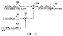
- the total cell voltage as shown by output 92 from the summing node 90 is used as a dividend labeled total_cell_volts and is divided by the total cell 84 count (K_TOTAL_CELLS_CNT) forming the stack 80 as shown by the constant 96 in step 94.
- the output of the division step is the average cell volts (cell_volts_ave) as shown by reference number 98 for the stack 80.
- the method of the present invention may be implemented in hardware or software.
- a software implementation is described herein due to its easy adaptability in the controller or EECM 70.
- a constant 100 labeled K_CLSTR_FILL_CNT is used to represent the difference between the number of cells 84 in each of the first clusters 86 and the number of cells 84 in the second or last cluster 87.
- the constant 100 equals one (4-3).
- the constant 100 is multiplied by the average cell voltage (cell_volts_ave) 98 in step 102.
- the result is summed with a separate input (act_clstr_volts(n)) 103 representing the actual measured voltage across the second, last cluster 87 as generated by the summing node or junction 89 in Figure 3.
- the resulting output 106 labeled "clstr_volts(n)" represents a padded or pseudo total voltage for the cells 84 in the second cluster 87 as if the last cluster 87 contains the same number of cells 84 as in all of the first clusters 86.
- each of the cluster voltages output from the respective summer nodes 89 and 91 can be separately input to a standard voltage monitoring circuit and treated identically to detect a low voltage of any one cluster despite the fact that the last cluster 87 contains a different number of cells 84 than the number of cells 84 in the other clusters 86.
- the output 106 is generated continuously during operation of the fuel cell 22 to provide continuous monitoring of the second cluster 87 and a recalculation of the pseudo voltage of the cluster 87 for use by the monitoring circuit.
- a unique method of equalizing cluster voltages in a fuel cell for use by a fuel cell monitoring circuit wherein a common monitoring circuit or method can be used with fuel cell clusters containing any identical number of cells, and particularly, where at least one of the cells has a different number of cells than the number of cells in the remaining clusters of the stack.
- the present method is also transparent to the number of cells forming each cluster thereby enabling its use along with the corresponding fuel cell monitoring circuit with fuel cell stacks containing any number of cells and even fuel cell stacks from different manufacturers.
Abstract
Description
Claims (4)
- In a method of operating a fuel cell apparatus wherein a hydrogen-rich stream is supplied to a stack of fuel cells, wherein the fuel cell stack includes a plurality of first clusters formed of identical number of fuel cells and at least one second cluster formed of a different number of fuel cells, the improvement comprising:measuring the voltage across the entire fuel cell stack;measuring the voltage across the second cluster of fuel cells; andcreating a pseudo cluster voltage for the second cluster based on the average cell voltage of all of the cells in the fuel cell stack, the actual voltage across the second cluster and the difference between the number of cells in the first clusters and the number of cells in the second cluster.
- The improvement of claim 1 wherein the step of creating the pseudo cluster voltage for the second cluster comprises the steps of:(a) measuring the total cell voltage across all of the fuel cells in the stack;(b) determining the average cell voltage for the entire stack;(c) multiplying the average cell voltage for the entire stack by the difference between the number of cells in the first clusters and the number of cells in the second cluster; and(d) adding the product of (c) to the actual measured voltage across the second cluster.
- The improvement of claim 2 further comprising the steps of:establishing a constant equal to the difference between the number of cells in each of the first clusters and the number of cells in the second cluster;multiplying the constant by the average cell voltage across the entire stack; andadding the resultant product of step (b) to the actual measured voltage across the second cluster.
- In a method of operating a fuel cell apparatus wherein a hydrogen-rich stream is supplied to a stack of fuel cells, wherein the fuel cell stack includes a plurality of first clusters formed of identical number of fuel cells and at least one second cluster formed of a different number of fuel cells, the improvement comprising:measuring the voltage across the entire fuel cell stack;measuring the voltage across the second cluster of fuel cells; andadjusting the measured voltage across the second cluster of fuel cells by a factor equivalent to the average cell voltage for each fuel cell difference between the number of fuel cells in the second cluster and the number fuel cells in the first cluster.
Applications Claiming Priority (2)
| Application Number | Priority Date | Filing Date | Title |
|---|---|---|---|
| US348245 | 1999-07-02 | ||
| US09/348,245 US6455180B1 (en) | 1999-07-02 | 1999-07-02 | Flexible method for monitoring fuel cell voltage |
Publications (2)
| Publication Number | Publication Date |
|---|---|
| EP1065740A2 true EP1065740A2 (en) | 2001-01-03 |
| EP1065740A3 EP1065740A3 (en) | 2001-08-22 |
Family
ID=23367199
Family Applications (1)
| Application Number | Title | Priority Date | Filing Date |
|---|---|---|---|
| EP00110375A Withdrawn EP1065740A3 (en) | 1999-07-02 | 2000-05-15 | Flexible method for monitoring fuel cell voltage |
Country Status (4)
| Country | Link |
|---|---|
| US (1) | US6455180B1 (en) |
| EP (1) | EP1065740A3 (en) |
| JP (1) | JP3429478B2 (en) |
| CA (1) | CA2308724A1 (en) |
Families Citing this family (14)
| Publication number | Priority date | Publication date | Assignee | Title |
|---|---|---|---|---|
| US6816797B2 (en) * | 2000-09-29 | 2004-11-09 | Hydrogenics Corporation | System and method for measuring fuel cell voltage and high frequency resistance |
| AU2003285252A1 (en) * | 2002-12-03 | 2004-06-23 | Hydrogenics Corporation | Method and apparatus for monitoring fuel cell voltages |
| DE112004000227T5 (en) * | 2003-02-04 | 2006-01-19 | Hydrogenics Corp., Mississauga | System and method for measuring internal resistance of electrochemical devices |
| EP1487044A3 (en) * | 2003-04-17 | 2006-07-19 | Matsushita Electric Industrial Co., Ltd. | Method for detecting possible structural deficiencies of a polymer electrolyte fuel cell |
| US20050110464A1 (en) * | 2003-11-25 | 2005-05-26 | Baker Howard S. | Fuel cell voltage monitoring system |
| US20050191537A1 (en) * | 2004-02-27 | 2005-09-01 | Belchuk Mark A. | Fuel cell gasket having an integrated sensor |
| US20050260463A1 (en) | 2004-05-21 | 2005-11-24 | Chapman Ivan D | Fluid flow pulsing for increased stability in PEM fuel cell |
| JP5326423B2 (en) | 2008-08-20 | 2013-10-30 | トヨタ自動車株式会社 | FUEL CELL SYSTEM AND FUEL CELL STATE DETECTION METHOD |
| US20100114513A1 (en) * | 2008-10-31 | 2010-05-06 | Gm Global Technology Operations, Inc. | Estimating minimum voltage of fuel cells |
| DE102008044271B4 (en) * | 2008-12-02 | 2023-07-06 | Robert Bosch Gmbh | Procedure for checking the function of an electrical heating device |
| CA2763056C (en) * | 2009-05-22 | 2018-07-24 | Battelle Memorial Institute | Integrated fuel processor and fuel cell system control method |
| US8450965B2 (en) * | 2010-07-20 | 2013-05-28 | GM Global Technology Operations LLC | Stack-powered fuel cell monitoring device with prioritized arbitration |
| JP6164199B2 (en) * | 2014-11-15 | 2017-07-19 | トヨタ自動車株式会社 | Power supply system and fuel cell voltage control method |
| JP7238848B2 (en) * | 2020-04-20 | 2023-03-14 | トヨタ自動車株式会社 | fuel cell system |
Citations (4)
| Publication number | Priority date | Publication date | Assignee | Title |
|---|---|---|---|---|
| WO1991019328A1 (en) * | 1990-06-08 | 1991-12-12 | Ballard Power Systems | Method and apparatus for monitoring fuel cell performance |
| US5085949A (en) * | 1991-02-05 | 1992-02-04 | Kabushiki Kaisha Toshiba | Fuel cell generation system |
| DE19523260A1 (en) * | 1995-06-27 | 1997-03-20 | Daimler Benz Ag | Monitoring output capability of multi-cell voltage sources e.g. fuel-cell type batteries for electric vehicles |
| EP0918363A1 (en) * | 1997-11-20 | 1999-05-26 | Siemens Aktiengesellschaft | Method and device for monitoring a selected group of fuel cells of a high temperature fuel cell stack |
Family Cites Families (27)
| Publication number | Priority date | Publication date | Assignee | Title |
|---|---|---|---|---|
| US4128700A (en) | 1977-11-26 | 1978-12-05 | United Technologies Corp. | Fuel cell power plant and method for operating the same |
| US4293315A (en) | 1979-03-16 | 1981-10-06 | United Technologies Corporation | Reaction apparatus for producing a hydrogen containing gas |
| US4659634A (en) | 1984-12-18 | 1987-04-21 | Struthers Ralph C | Methanol hydrogen fuel cell system |
| US4555454A (en) | 1985-04-17 | 1985-11-26 | Gould, Inc. | Reinforced consumable electrode, electrochemical cell and method |
| US4670359A (en) | 1985-06-10 | 1987-06-02 | Engelhard Corporation | Fuel cell integrated with steam reformer |
| US4642272A (en) | 1985-12-23 | 1987-02-10 | International Fuel Cells Corporation | Integrated fuel cell and fuel conversion apparatus |
| US4650727A (en) | 1986-01-28 | 1987-03-17 | The United States Of America As Represented By The United States Department Of Energy | Fuel processor for fuel cell power system |
| US4816353A (en) | 1986-05-14 | 1989-03-28 | International Fuel Cells Corporation | Integrated fuel cell and fuel conversion apparatus |
| US4678723A (en) | 1986-11-03 | 1987-07-07 | International Fuel Cells Corporation | High pressure low heat rate phosphoric acid fuel cell stack |
| JPH02168569A (en) | 1988-08-22 | 1990-06-28 | Fuji Electric Co Ltd | Fuel battery power generating system |
| US4994331A (en) | 1989-08-28 | 1991-02-19 | International Fuel Cells Corporation | Fuel cell evaporative cooling using fuel as a carrier gas |
| US5271916A (en) | 1991-07-08 | 1993-12-21 | General Motors Corporation | Device for staged carbon monoxide oxidation |
| DE69213917T2 (en) | 1991-12-24 | 1997-02-27 | Toshiba Kawasaki Kk | Power plant with fuel cells |
| US5272017A (en) | 1992-04-03 | 1993-12-21 | General Motors Corporation | Membrane-electrode assemblies for electrochemical cells |
| US5372617A (en) | 1993-05-28 | 1994-12-13 | The Charles Stark Draper Laboratory, Inc. | Hydrogen generation by hydrolysis of hydrides for undersea vehicle fuel cell energy systems |
| US5429886A (en) | 1993-08-30 | 1995-07-04 | Struthers; Ralph C. | Hydrocarbon (hydrogen)/air aerogel catalyzed carbon electrode fuel cell system |
| US5484577A (en) | 1994-05-27 | 1996-01-16 | Ballard Power System Inc. | Catalytic hydrocarbon reformer with enhanced internal heat transfer mechanism |
| US5518828A (en) | 1994-07-21 | 1996-05-21 | Bechtel Group, Inc. | Thermal integration of an air-cooled fuel cell stack |
| US5518705A (en) | 1994-08-22 | 1996-05-21 | Ballard Power Systems Inc. | Method and apparatus for the two-stage selective oxidation of carbon monoxide in a hydrogen-containing gas mixture |
| US5484666A (en) | 1994-09-20 | 1996-01-16 | Ballard Power Systems Inc. | Electrochemical fuel cell stack with compression mechanism extending through interior manifold headers |
| US5554453A (en) | 1995-01-04 | 1996-09-10 | Energy Research Corporation | Carbonate fuel cell system with thermally integrated gasification |
| EP0741428A1 (en) | 1995-05-04 | 1996-11-06 | FINMECCANICA S.p.A. AZIENDA ANSALDO | A supply system for fuel cells of the S.P.E. (SOLID POLYMER ELECTROLYTE) type for hybrid vehicles). |
| US5702838A (en) | 1995-08-18 | 1997-12-30 | Matsushita Electric Industrial Co., Ltd. | Fuel cell device equipped with catalyst material for removing carbon monoxide and method for removing carbon monoxide |
| US5763113A (en) | 1996-08-26 | 1998-06-09 | General Motors Corporation | PEM fuel cell monitoring system |
| US5637415A (en) | 1996-08-30 | 1997-06-10 | General Motors Corporation | Controlled CO preferential oxidation |
| US5789091C1 (en) | 1996-11-19 | 2001-02-27 | Ballard Power Systems | Electrochemical fuel cell stack with compression bands |
| US6096449A (en) * | 1997-11-20 | 2000-08-01 | Avista Labs | Fuel cell and method for controlling same |
-
1999
- 1999-07-02 US US09/348,245 patent/US6455180B1/en not_active Expired - Lifetime
-
2000
- 2000-05-15 EP EP00110375A patent/EP1065740A3/en not_active Withdrawn
- 2000-05-17 CA CA002308724A patent/CA2308724A1/en not_active Abandoned
- 2000-06-30 JP JP2000199246A patent/JP3429478B2/en not_active Expired - Fee Related
Patent Citations (4)
| Publication number | Priority date | Publication date | Assignee | Title |
|---|---|---|---|---|
| WO1991019328A1 (en) * | 1990-06-08 | 1991-12-12 | Ballard Power Systems | Method and apparatus for monitoring fuel cell performance |
| US5085949A (en) * | 1991-02-05 | 1992-02-04 | Kabushiki Kaisha Toshiba | Fuel cell generation system |
| DE19523260A1 (en) * | 1995-06-27 | 1997-03-20 | Daimler Benz Ag | Monitoring output capability of multi-cell voltage sources e.g. fuel-cell type batteries for electric vehicles |
| EP0918363A1 (en) * | 1997-11-20 | 1999-05-26 | Siemens Aktiengesellschaft | Method and device for monitoring a selected group of fuel cells of a high temperature fuel cell stack |
Also Published As
| Publication number | Publication date |
|---|---|
| EP1065740A3 (en) | 2001-08-22 |
| JP3429478B2 (en) | 2003-07-22 |
| US6455180B1 (en) | 2002-09-24 |
| JP2001023664A (en) | 2001-01-26 |
| CA2308724A1 (en) | 2001-01-02 |
Similar Documents
| Publication | Publication Date | Title |
|---|---|---|
| US6406806B1 (en) | Fuel cell voltage monitoring and system control | |
| EP1069636B1 (en) | Fuel cell stack monitoring and system control | |
| US6528191B1 (en) | Apparatus for monitoring a hydrogen containing gas stream | |
| EP1067614B1 (en) | Fuel cell system logic for differentiating between rapid and normal shutdown commands | |
| CA2240298C (en) | Fuel cell system with combustor-heated reformer | |
| EP0924786B1 (en) | Fuel cell system combustor | |
| US6436561B1 (en) | Methanol tailgas combustor control method | |
| US6455180B1 (en) | Flexible method for monitoring fuel cell voltage | |
| US6451465B1 (en) | Method for operating a combustor in a fuel cell system | |
| US6416893B1 (en) | Method and apparatus for controlling combustor temperature during transient load changes | |
| US6602624B1 (en) | Control apparatus and method for efficiently heating a fuel processor in a fuel cell system | |
| US6376112B1 (en) | Controlled shutdown of a fuel cell | |
| EP1128456A2 (en) | Method and apparatus for preventing cell reversal in a fuel cell stack | |
| US20090246568A1 (en) | System for the generation of electric power on-board a motor vehicle which is equipped with a fuel cell and associated method | |
| Keskula et al. | Fuel cell stack monitoring and system control |
Legal Events
| Date | Code | Title | Description |
|---|---|---|---|
| PUAI | Public reference made under article 153(3) epc to a published international application that has entered the european phase |
Free format text: ORIGINAL CODE: 0009012 |
|
| AK | Designated contracting states |
Kind code of ref document: A2 Designated state(s): AT BE CH CY DE DK ES FI FR GB GR IE IT LI LU MC NL PT SE |
|
| AX | Request for extension of the european patent |
Free format text: AL;LT;LV;MK;RO;SI |
|
| PUAL | Search report despatched |
Free format text: ORIGINAL CODE: 0009013 |
|
| AK | Designated contracting states |
Kind code of ref document: A3 Designated state(s): AT BE CH CY DE DK ES FI FR GB GR IE IT LI LU MC NL PT SE |
|
| AX | Request for extension of the european patent |
Free format text: AL;LT;LV;MK;RO;SI |
|
| RIC1 | Information provided on ipc code assigned before grant |
Free format text: 7H 01M 8/04 A, 7G 01R 31/36 B |
|
| 17P | Request for examination filed |
Effective date: 20011221 |
|
| AKX | Designation fees paid |
Free format text: DE FR GB |
|
| 17Q | First examination report despatched |
Effective date: 20071221 |
|
| RAP1 | Party data changed (applicant data changed or rights of an application transferred) |
Owner name: GM GLOBAL TECHNOLOGY OPERATIONS, INC. |
|
| RAP1 | Party data changed (applicant data changed or rights of an application transferred) |
Owner name: GM GLOBAL TECHNOLOGY OPERATIONS, INC. |
|
| RAP1 | Party data changed (applicant data changed or rights of an application transferred) |
Owner name: GM GLOBAL TECHNOLOGY OPERATIONS LLC |
|
| RIC1 | Information provided on ipc code assigned before grant |
Ipc: H01M 8/04537 20160101ALI20160622BHEP Ipc: G01R 31/36 20060101AFI20160622BHEP Ipc: G01R 31/00 20060101ALI20160622BHEP |
|
| GRAP | Despatch of communication of intention to grant a patent |
Free format text: ORIGINAL CODE: EPIDOSNIGR1 |
|
| INTG | Intention to grant announced |
Effective date: 20160804 |
|
| STAA | Information on the status of an ep patent application or granted ep patent |
Free format text: STATUS: THE APPLICATION IS DEEMED TO BE WITHDRAWN |
|
| 18D | Application deemed to be withdrawn |
Effective date: 20161215 |