EP1065546A1 - Incorporation of UV transparent perlescent pigments to UV curable optical fiber materials - Google Patents
Incorporation of UV transparent perlescent pigments to UV curable optical fiber materials Download PDFInfo
- Publication number
- EP1065546A1 EP1065546A1 EP00401658A EP00401658A EP1065546A1 EP 1065546 A1 EP1065546 A1 EP 1065546A1 EP 00401658 A EP00401658 A EP 00401658A EP 00401658 A EP00401658 A EP 00401658A EP 1065546 A1 EP1065546 A1 EP 1065546A1
- Authority
- EP
- European Patent Office
- Prior art keywords
- optical fiber
- pigment
- perlescent
- coating
- mica particles
- Prior art date
- Legal status (The legal status is an assumption and is not a legal conclusion. Google has not performed a legal analysis and makes no representation as to the accuracy of the status listed.)
- Granted
Links
- 239000000049 pigment Substances 0.000 title claims abstract description 82
- 239000013307 optical fiber Substances 0.000 title claims abstract description 49
- 239000000463 material Substances 0.000 title description 3
- 238000010348 incorporation Methods 0.000 title 1
- 238000000576 coating method Methods 0.000 claims abstract description 73
- 239000011248 coating agent Substances 0.000 claims abstract description 60
- 229920000642 polymer Polymers 0.000 claims abstract description 33
- 239000002245 particle Substances 0.000 claims abstract description 29
- 239000010445 mica Substances 0.000 claims abstract description 27
- 229910052618 mica group Inorganic materials 0.000 claims abstract description 27
- 239000000835 fiber Substances 0.000 claims description 27
- GWEVSGVZZGPLCZ-UHFFFAOYSA-N Titan oxide Chemical compound O=[Ti]=O GWEVSGVZZGPLCZ-UHFFFAOYSA-N 0.000 claims description 25
- 230000005855 radiation Effects 0.000 claims description 15
- 239000011159 matrix material Substances 0.000 claims description 13
- 238000005253 cladding Methods 0.000 claims description 4
- 230000003287 optical effect Effects 0.000 claims description 2
- 230000000903 blocking effect Effects 0.000 claims 2
- 230000001965 increasing effect Effects 0.000 abstract description 8
- 230000002708 enhancing effect Effects 0.000 abstract description 2
- 238000002834 transmittance Methods 0.000 abstract 1
- 239000010410 layer Substances 0.000 description 22
- 239000000975 dye Substances 0.000 description 7
- OGIDPMRJRNCKJF-UHFFFAOYSA-N titanium oxide Inorganic materials [Ti]=O OGIDPMRJRNCKJF-UHFFFAOYSA-N 0.000 description 4
- 239000003086 colorant Substances 0.000 description 3
- 239000002861 polymer material Substances 0.000 description 3
- NIXOWILDQLNWCW-UHFFFAOYSA-M Acrylate Chemical compound [O-]C(=O)C=C NIXOWILDQLNWCW-UHFFFAOYSA-M 0.000 description 2
- 241000251468 Actinopterygii Species 0.000 description 1
- OKTJSMMVPCPJKN-UHFFFAOYSA-N Carbon Chemical compound [C] OKTJSMMVPCPJKN-UHFFFAOYSA-N 0.000 description 1
- 239000004721 Polyphenylene oxide Substances 0.000 description 1
- 241000220317 Rosa Species 0.000 description 1
- 150000001252 acrylic acid derivatives Chemical class 0.000 description 1
- 230000002411 adverse Effects 0.000 description 1
- 230000005540 biological transmission Effects 0.000 description 1
- 239000001045 blue dye Substances 0.000 description 1
- 229910052799 carbon Inorganic materials 0.000 description 1
- 239000003795 chemical substances by application Substances 0.000 description 1
- 239000011247 coating layer Substances 0.000 description 1
- 238000004040 coloring Methods 0.000 description 1
- 239000000356 contaminant Substances 0.000 description 1
- 230000003247 decreasing effect Effects 0.000 description 1
- 238000010894 electron beam technology Methods 0.000 description 1
- UHESRSKEBRADOO-UHFFFAOYSA-N ethyl carbamate;prop-2-enoic acid Chemical compound OC(=O)C=C.CCOC(N)=O UHESRSKEBRADOO-UHFFFAOYSA-N 0.000 description 1
- 230000009931 harmful effect Effects 0.000 description 1
- 239000007788 liquid Substances 0.000 description 1
- 230000004048 modification Effects 0.000 description 1
- 238000012986 modification Methods 0.000 description 1
- 229920000728 polyester Polymers 0.000 description 1
- 229920000570 polyether Polymers 0.000 description 1
- 229920005594 polymer fiber Polymers 0.000 description 1
- 229920001296 polysiloxane Polymers 0.000 description 1
- MLMVPBFKPWONNM-UHFFFAOYSA-N prop-2-enoic acid;urea Chemical compound NC(N)=O.OC(=O)C=C MLMVPBFKPWONNM-UHFFFAOYSA-N 0.000 description 1
- KCTAWXVAICEBSD-UHFFFAOYSA-N prop-2-enoyloxy prop-2-eneperoxoate Chemical compound C=CC(=O)OOOC(=O)C=C KCTAWXVAICEBSD-UHFFFAOYSA-N 0.000 description 1
- 230000001681 protective effect Effects 0.000 description 1
- 239000001044 red dye Substances 0.000 description 1
- 229920005573 silicon-containing polymer Polymers 0.000 description 1
- 239000010454 slate Substances 0.000 description 1
- -1 urethane epoxides Chemical class 0.000 description 1
- XLYOFNOQVPJJNP-UHFFFAOYSA-N water Chemical compound O XLYOFNOQVPJJNP-UHFFFAOYSA-N 0.000 description 1
- 239000012463 white pigment Substances 0.000 description 1
Images

Classifications
-
- G—PHYSICS
- G02—OPTICS
- G02B—OPTICAL ELEMENTS, SYSTEMS OR APPARATUS
- G02B6/00—Light guides; Structural details of arrangements comprising light guides and other optical elements, e.g. couplings
- G02B6/44—Mechanical structures for providing tensile strength and external protection for fibres, e.g. optical transmission cables
- G02B6/4479—Manufacturing methods of optical cables
- G02B6/4482—Code or colour marking
Definitions
- the present invention relates to coated optical fibers and, more specifically, to an improved manner of color coding the coated optical fibers wherein the manner of color coding also produces faster cure speeds in the optical fiber coating.
- the pigments used to color code optical fibers block light. Because the traditional pigments block light, a low amount of ultraviolet (UV) radiation is allowed to pass through the coating containing the traditional pigments. The amount of UV radiation allowed to pass through the pigment containing layer directly affects cure time of the pigment containing layer as well as any other curable layers underneath thereof. Therefore, the use of traditional pigments is an impediment to increased curing time of optical fiber coatings.
- UV radiation ultraviolet
- US Patent 5,259,060 to Edward et al. discloses a coated optical fiber which includes an ink layer, and a layer containing an opaque white pigmented layer.
- the opaque white layer includes sufficient white pigment to render it light-reflective and substantially opaque to visible light.
- the pigments used to produce the opaque white layer are traditional pigments which block UV radiation and, therefore, are an impediment to faster curing speeds.
- An object of the present invention is to overcome the disadvantages of the prior art. More specifically, an object of the present invention is to increase cure speed of optical fiber coatings while maintaining easily identifiable color coding. A further object is to increase cure speed of optical fiber coatings while enhancing the brightness, or visibility, of the colors in an optical fiber coating.
- a perlescent pigment is used in the polymer coating materials of an optical fiber to achieve easy color identification of the optical fiber, as well as to achieve an increased amount of UV transmissibility which thereby produces faster curing speeds.
- the present invention is of particular importance when the optical fiber contains a hermetic coating.
- the hermetic coating acts to protect the fiber from the potentially harmful effects of water vapor or gaseous contaminants affecting optical transmission characteristics or fiber strength.
- the hermetic coating is typically a metallic or carbon-based coating which tends to absorb light and present a dark background. Therefore, when present, the hermetic coating makes effective color coding even more difficult.
- Increasing the proportion of light transmitted through the coating is achieved in accordance with the invention by minimizing or avoiding the inclusion of additional opacifying agents in the pigmented layer, i.e., substituting a perlescent pigment material for the traditional pigments used for coloring optical fiber coatings.
- a perlescent pigment is used in the same coating as the colored pigments, or in a layer under the pigmented layer, to thereby increase the amount of light impinging on the colored pigment.
- the brightness or visibility of the pigment present in the colored layers is intensified.
- the perlescent pigment may include, for example, mica particles, mica particles coated with a pigment, fish scales, or any other type of particle that gives a metallic-looking finish to the polymer in which it is disposed.
- the perlescent pigment is made of mica particles.
- Mica particles are more transparent to UV radiation below about 400 nm, whereas wavelengths of about 250 to about 400 nm are used to cure the polymer coatings.
- the mica particles transmit more of the UV radiation wavelengths used for curing the polymer coating.
- mica particles reflect light above about 420 nm, including light in the visible range and, therefore, enhance the brightness or visibility of color for fiber identification.
- the mica particles allow the underlying polymer coatings to be cured at a fast rate while at the same time producing an enhanced, easily identifiable, color in the optical fiber.
- the average width of the mica particles may range from 1 ⁇ m to the order of thickness of the coating in which they are contained. For example, when the thickness of the coating is on the order of 15 ⁇ m, particles having an average width larger than 15 ⁇ m would not work well.
- the average width of the mica particles is from 1 ⁇ m to 10 pm which produces good results without producing additional stress on the fiber core, and without clogging the dies with which the optical fiber is produced.
- the average width of the mica particles is 8 ⁇ m.
- the mica particles may be coated with a form of titanium oxide (TiO 2 ) to produce a "white” color.
- TiO 2 titanium oxide
- a "white” perlescent pigment is useful in reflecting light to enhance the brightness and visibility of other colored pigments. Further, when used alone, the perlescent pigment produces an easily identifiable "white” colored fiber.
- composition of the polymers used in the optical fiber coatings in accordance with the present invention is not critical. Any of the well-known curable liquid polymers known to have utility for the application of optical fiber coatings may be employed. Examples of some well-known polymer types which have previously been used for protective and/or colored optical fiber coatings include urea-acrylate, urethane-acrylate, epoxy-acrylate, polyether acrylate, polyester acrylate, urethane epoxides, silicone acrylates, and silicone polymers. Either thermally curable or radiation curable forms of these coatings may be used.
- the polymer used to coat the optical fibers may be a UV curable polymer, an electron beam curable polymer, or any other suitable polymer. However, the perlescent pigments of the present invention are particularly useful with UV curable polymers. Therefore, the specification describes the present invention in connection with optical fiber coatings made of UV curable polymers, with the understanding that the polymer may be of any suitable type.
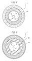
- an optical fiber 1 includes a core 10, a cladding 12, a primary coating 20 and a secondary coating 22. Further, the optical fiber may contain a hermetic coating 14 and/or an ink layer 24.
- the primary coating 20 and secondary coating 22 are made of a UV curable polymer.
- Figure 1 shows a secondary coating 22' containing a perlescent pigment.
- the perlescent pigment may be, for example, either mica particles, or mica particles coated with a pigment and, in particular, coated with a form of TiO 2 .
- the secondary coating 22' may also contain other pigments which correspond to other colors for identification.
- the "white” perlescent pigment along with other colored pigments, the visibility of the other colored pigments is enhanced.
- the UV transmittability of the colored coating is enhanced, thereby producing a faster cure speed.
- the perlescent pigment may be included in a different coating of the optical fiber, but still have the same advantages as described in connection with the optical fiber of Figure 1.
- some optical fibers may contain an ink layer 24 which surrounds the secondary coating 22.
- colored pigments are not contained in either the primary coating 20 or the secondary coating 22 but, instead, are included in the separate ink layer 24.
- a perlescent pigment may be added to any one, or more, of the secondary coating 22, and the ink layer 24.
- the perlescent pigment When the perlescent pigment is included in the secondary coating 22, it enhances the visibility of the colored pigment in the ink layer 24.
- the visibility of the pigment in the ink layer is enhanced due to light which is reflected by the perlescent pigment in the secondary coating 24.
- the perlescent pigment does not block as much UV light used for curing, the cure time is not adversely affected by the inclusion of the perlescent pigment.
- the perlescent pigment When the perlescent pigment is included in the ink layer 24, it enhances the visibility of the colored pigment as well as produces a faster cure speed. Because the perlescent pigment reflects light in the visible range, it brightens, or enhances the visibility of, the colored pigments. Also, because the perlescent pigment replaces some of the colored pigment in the ink layer 24, there is less pigment which blocks the UV radiation used in curing. Further, because the perlescent pigment, which replaces the colored pigment, transmits UV radiation used in curing, the cure speed is increased.
- the perlescent pigment of the present invention may be used in a fiber optic ribbon.
- Figure 3 shows a fiber optic ribbon which includes optical fibers 1 disposed in a matrix material 3.
- the optical fibers 1 as shown in Figure 4 include a coating 2.
- the optical fibers 1 may be any of the types shown in Figures 1-2, or any other suitable type.
- the coating 2 may include: the primary coating 20 and the secondary coating 22; or the primary coating 20, the secondary coating 22, and the ink layer 24.
- the coating 2 may be the only coating on the optical fiber.
- the matrix material 3 is made of a polymer material, similar to the polymer material of the optical fiber coating, and may include pigments therein so that different fiber optic ribbons can be identified.
- perlescent pigments are included in the matrix material 3 of a fiber optic ribbon.
- Perlescent pigments in the matrix material enhance the brightness, or visibility of, colored pigments in the matrix material, thereby facilitating identification of different fiber optic ribbons. Further, because of the UV transmittability of the perlescent pigments, the cure speed of the matrix material is increased.
- any of the above polymer materials may include “dyes”. Suitable “dyes” are described in US Patent 5,074,643 to Petisce which is incorporated herein by reference.
- the perlescent pigments of the present invention when used without any other colored pigment or dye, can be used to generate a "white” color.
- the mica particles ⁇ or other particles which give a metallic-looking finish ⁇ may be used without any coating thereon.
- the mica particles may be coated with a form of TiO 2 and, in particular, a rutile or anatase.
- the perlescent pigments may be used in a coating along with the "dyes" to thereby enhance the optical fiber color.
- the perlescent pigment produces: a better slate when combined with a black dye; a better rose, when combined with a red dye; and a better aqua, when combined with a light blue dye.
- the inclusion of the perlescent pigments along with the dyes gives an increased UV transmittability and, therefore, a faster cure speed.
Landscapes
- Physics & Mathematics (AREA)
- Engineering & Computer Science (AREA)
- Manufacturing & Machinery (AREA)
- General Physics & Mathematics (AREA)
- Optics & Photonics (AREA)
- Optical Fibers, Optical Fiber Cores, And Optical Fiber Bundles (AREA)
- Paints Or Removers (AREA)
- Surface Treatment Of Glass Fibres Or Filaments (AREA)
Abstract
Description
Claims (24)
- An optical fiber comprising:a core:a cladding surrounding said core; anda polymer coating surrounding said cladding, wherein said polymer coating includes a perlescent pigment therein.
- The optical fiber according to claim 1, wherein said perlescent pigment includes mica particles.
- The optical fiber according to claim 2, wherein said mica particles are coated with a form of TiO2.
- The optical fiber according to claim 3, wherein said form of TiO2 is rutile.
- The optical fiber according to claim 3, wherein said form of TiO2 is anatase.
- The optical fiber according to any of claims 2 to 5. wherein said mica particles have an average width of from 1 µm to 15 µm.
- The optical liher according to claim 6, wherein said mica particles have an average width of from 1 µm to 10 µm.
- The optical fiber according to claim 7, wherein said mica particles have an average width of 8 µm.
- The optical fiber according to any of claims 1 to 8. wherein said polymer coating further includes a dye therein.
- The optical fiber according to any of claims 1 to 9, wherein said polymer coating further includes a UV blocking pigment therein.
- The optical fiber according to any of claims 1 to 10, wherein said polymer coating comprises a radiation curable polymer.
- The optical fiber according to any of claims 1 to 11, further comprising an ink layer adjacent to said polymer coating, wherein said perlescent pigment is included in one of said polymer coating and said ink layer.
- The optical fiber according to any of claims 1 to 12, wherein said polymer coating includes a primary coating surrounding said cladding and a secondary coating surrounding said primary coating, and wherein said perlescent pigment is disposed in said secondary coating.
- A fiber optic ribbon comprising:wherein said matrix material includes a perlescent pigment therein.a matrix material; andone or more optical fibers disposed in said matrix material,
- The fiber optic ribbon according to claim 14, wherein said perlescent pigment includes mica particles.
- The fiber optic ribbon according to claim 15. wherein said mica particles are coated with TiO2.
- The fiber optic ribbon according to claim 16, wherein said TiO2 is rutile.
- The fibel optic ribbon according to claim 16, wherein said TiO2 is anatase.
- The fiber optic ribbon according to any of claims 15 to 18, wherein said mica particles have an average width of from 1 µm to 15 µm.
- The fiber optic ribbon according to claim 19. wherein said mica particles have an average width of from 1 µm to 10 µm.
- The fiber optic ribbon according to claim 20, wherein said mica particles have an average width of 8 µm.
- The fiber optic ribbon according to any of claims 14 to 21, wherein said matrix material comprises a radiation curable polymer.
- The fiber optic ribbon according to any of claims 14 to 22, wherein said matrix material further includes a dye therein.
- The fiber optic ribbon according to any of claims 14 to 23, wherein said matrix material further includes a UV blocking pigment therein.
Applications Claiming Priority (2)
| Application Number | Priority Date | Filing Date | Title |
|---|---|---|---|
| US343050 | 1999-06-30 | ||
| US09/343,050 US6504982B1 (en) | 1999-06-30 | 1999-06-30 | Incorporation of UV transparent perlescent pigments to UV curable optical fiber materials |
Publications (2)
| Publication Number | Publication Date |
|---|---|
| EP1065546A1 true EP1065546A1 (en) | 2001-01-03 |
| EP1065546B1 EP1065546B1 (en) | 2007-08-01 |
Family
ID=23344467
Family Applications (1)
| Application Number | Title | Priority Date | Filing Date |
|---|---|---|---|
| EP00401658A Expired - Lifetime EP1065546B1 (en) | 1999-06-30 | 2000-06-13 | Incorporation of UV transparent perlescent pigments to UV curable optical fiber materials |
Country Status (5)
| Country | Link |
|---|---|
| US (1) | US6504982B1 (en) |
| EP (1) | EP1065546B1 (en) |
| JP (1) | JP4681711B2 (en) |
| CN (1) | CN1140826C (en) |
| DE (1) | DE60035741T2 (en) |
Cited By (2)
| Publication number | Priority date | Publication date | Assignee | Title |
|---|---|---|---|---|
| WO2003098307A1 (en) * | 2002-05-17 | 2003-11-27 | Sumitomo Electric Industries, Ltd. | Tape-like optical fiber core, production method therefor, tape core-carrying connector, tape core-carrying optical fiber array, and optical wiring system |
| FR2871796A1 (en) * | 2004-06-21 | 2005-12-23 | Alcatel Sa | METHOD AND INSTALLATION FOR MANUFACTURING A FIBER ELEMENT WITH A SELECTIVE LIGHT FILTER |
Families Citing this family (22)
| Publication number | Priority date | Publication date | Assignee | Title |
|---|---|---|---|---|
| US6630242B1 (en) * | 1999-07-30 | 2003-10-07 | Dsm N.V. | Radiation-curable composition with simultaneous color formation during cure |
| TW536640B (en) * | 2001-04-13 | 2003-06-11 | Furukawa Electric Co Ltd | Coated optical fiber |
| US20040037521A1 (en) * | 2002-08-22 | 2004-02-26 | Shunhe Xiong | Methods and apparatus for coloring optical fibers during draw |
| US7836946B2 (en) | 2002-10-31 | 2010-11-23 | Weatherford/Lamb, Inc. | Rotating control head radial seal protection and leak detection systems |
| US7400808B2 (en) * | 2003-01-10 | 2008-07-15 | The Furukawa Electric Co., Ltd. | Optical fiber, light amplifier, and light source |
| EP1452502A1 (en) * | 2003-02-28 | 2004-09-01 | Fitel Usa Corporation | Systems and methods involving optical fibers having seperate color layers |
| US8826988B2 (en) | 2004-11-23 | 2014-09-09 | Weatherford/Lamb, Inc. | Latch position indicator system and method |
| US7926593B2 (en) | 2004-11-23 | 2011-04-19 | Weatherford/Lamb, Inc. | Rotating control device docking station |
| JP4041499B2 (en) * | 2005-02-02 | 2008-01-30 | アルプス電気株式会社 | Magnetic head slider |
| US7876489B2 (en) * | 2006-06-05 | 2011-01-25 | Pixtronix, Inc. | Display apparatus with optical cavities |
| US7997345B2 (en) * | 2007-10-19 | 2011-08-16 | Weatherford/Lamb, Inc. | Universal marine diverter converter |
| US8844652B2 (en) | 2007-10-23 | 2014-09-30 | Weatherford/Lamb, Inc. | Interlocking low profile rotating control device |
| US8286734B2 (en) * | 2007-10-23 | 2012-10-16 | Weatherford/Lamb, Inc. | Low profile rotating control device |
| US9359853B2 (en) | 2009-01-15 | 2016-06-07 | Weatherford Technology Holdings, Llc | Acoustically controlled subsea latching and sealing system and method for an oilfield device |
| US8322432B2 (en) * | 2009-01-15 | 2012-12-04 | Weatherford/Lamb, Inc. | Subsea internal riser rotating control device system and method |
| US8347983B2 (en) | 2009-07-31 | 2013-01-08 | Weatherford/Lamb, Inc. | Drilling with a high pressure rotating control device |
| US8347982B2 (en) | 2010-04-16 | 2013-01-08 | Weatherford/Lamb, Inc. | System and method for managing heave pressure from a floating rig |
| US9175542B2 (en) | 2010-06-28 | 2015-11-03 | Weatherford/Lamb, Inc. | Lubricating seal for use with a tubular |
| RU2661064C1 (en) * | 2014-10-17 | 2018-07-11 | Сумитомо Электрик Индастриз, Лтд. | Optical fiber and optical fiber lace |
| EP3841417A4 (en) | 2018-08-21 | 2022-05-18 | Corning Research & Development Corporation | Optical ribbon with printing between opaque primary layer and colored secondary layer |
| EP3907251A1 (en) * | 2020-05-07 | 2021-11-10 | ABB Schweiz AG | Solid platelets used as filler in a uv curable thermoset resin to enhance the electrical insulation of high volt-age conductor bars |
| US20230220941A1 (en) * | 2022-01-10 | 2023-07-13 | Moray Group, Llc | Device and method for repairing pipe with a repair assembly having a lighting assembly |
Citations (3)
| Publication number | Priority date | Publication date | Assignee | Title |
|---|---|---|---|---|
| EP0582833A1 (en) * | 1992-08-11 | 1994-02-16 | Corning Incorporated | Coated optical fibers and method |
| WO1998056850A1 (en) * | 1997-06-13 | 1998-12-17 | M.A. Hannacolor | Concentrate compositions for imparting a translucent optical effect to transparent thermoplastic polymers |
| DE19924381A1 (en) * | 1998-05-28 | 1999-12-09 | Dsm Nv | Radiation curable ink composition for coated optical glass fibers |
Family Cites Families (10)
| Publication number | Priority date | Publication date | Assignee | Title |
|---|---|---|---|---|
| US4465797A (en) * | 1983-07-15 | 1984-08-14 | Shell Oil Company | Reinforced polymer compositions and their preparation |
| US4741778A (en) * | 1986-03-22 | 1988-05-03 | Nippon Telegraph & Telephone Corporation | Thermal control coating composition |
| JP2907544B2 (en) * | 1989-05-12 | 1999-06-21 | ディーエスエム ナムローゼ フェンノートシャップ | Photocurable colored secondary optical fiber coating |
| JPH0387706A (en) * | 1989-06-26 | 1991-04-12 | Sumitomo Electric Ind Ltd | Coated optical fiber |
| US5354348A (en) | 1991-05-12 | 1994-10-11 | Mitsubishi Cable Industries, Ltd. | Method for producing silica glass optical fiber with carbon coating |
| JPH06271813A (en) * | 1993-03-23 | 1994-09-27 | Kansai Paint Co Ltd | Composition for coating |
| US5933559A (en) * | 1996-07-22 | 1999-08-03 | Dsm N.V. | Radiation-curable cross-linked ribbon matrix material for bonding an array of coated optical glass fibers |
| US6130980A (en) * | 1997-05-06 | 2000-10-10 | Dsm N.V. | Ribbon assemblies and ink coating compositions for use in forming the ribbon assemblies |
| US6026207A (en) * | 1997-05-21 | 2000-02-15 | Alcatel | Black appearing color coating for optical fiber and method using same |
| US6113683A (en) * | 1997-11-25 | 2000-09-05 | Ciba Specialty Chemicals Corporation | Colored pearlescent pigments |
-
1999
- 1999-06-30 US US09/343,050 patent/US6504982B1/en not_active Expired - Fee Related
-
2000
- 2000-06-01 JP JP2000163884A patent/JP4681711B2/en not_active Expired - Fee Related
- 2000-06-09 CN CNB001181300A patent/CN1140826C/en not_active Expired - Fee Related
- 2000-06-13 DE DE60035741T patent/DE60035741T2/en not_active Expired - Lifetime
- 2000-06-13 EP EP00401658A patent/EP1065546B1/en not_active Expired - Lifetime
Patent Citations (3)
| Publication number | Priority date | Publication date | Assignee | Title |
|---|---|---|---|---|
| EP0582833A1 (en) * | 1992-08-11 | 1994-02-16 | Corning Incorporated | Coated optical fibers and method |
| WO1998056850A1 (en) * | 1997-06-13 | 1998-12-17 | M.A. Hannacolor | Concentrate compositions for imparting a translucent optical effect to transparent thermoplastic polymers |
| DE19924381A1 (en) * | 1998-05-28 | 1999-12-09 | Dsm Nv | Radiation curable ink composition for coated optical glass fibers |
Cited By (5)
| Publication number | Priority date | Publication date | Assignee | Title |
|---|---|---|---|---|
| WO2003098307A1 (en) * | 2002-05-17 | 2003-11-27 | Sumitomo Electric Industries, Ltd. | Tape-like optical fiber core, production method therefor, tape core-carrying connector, tape core-carrying optical fiber array, and optical wiring system |
| EP1507156A4 (en) * | 2002-05-17 | 2005-09-07 | Sumitomo Electric Industries | TAPE-TYPE OPTICAL FIBER HEAD, CORRESPONDING PRODUCTION METHOD, CONNECTOR WITH RIBBON-TYPE HEAD, OPTICAL FIBER ASSEMBLY WITH RIBBON-TYPE HEART, AND OPTICAL WIRING SYSTEM |
| US8811783B2 (en) | 2002-05-17 | 2014-08-19 | Sumitomo Electric Industries, Ltd. | Tape-like optical fiber core, production method therefor, tape core-carrying connector, tape core-carrying optical fiber array, and optical wiring system |
| FR2871796A1 (en) * | 2004-06-21 | 2005-12-23 | Alcatel Sa | METHOD AND INSTALLATION FOR MANUFACTURING A FIBER ELEMENT WITH A SELECTIVE LIGHT FILTER |
| WO2005124417A1 (en) * | 2004-06-21 | 2005-12-29 | Draka Comteq B.V. | Method and installation for producing a fibered element with a light-selective filter |
Also Published As
| Publication number | Publication date |
|---|---|
| CN1279404A (en) | 2001-01-10 |
| JP4681711B2 (en) | 2011-05-11 |
| US6504982B1 (en) | 2003-01-07 |
| EP1065546B1 (en) | 2007-08-01 |
| DE60035741T2 (en) | 2007-12-06 |
| JP2001031448A (en) | 2001-02-06 |
| US20020191930A1 (en) | 2002-12-19 |
| DE60035741D1 (en) | 2007-09-13 |
| CN1140826C (en) | 2004-03-03 |
Similar Documents
| Publication | Publication Date | Title |
|---|---|---|
| US6504982B1 (en) | Incorporation of UV transparent perlescent pigments to UV curable optical fiber materials | |
| US5259060A (en) | Coated optical fibers and method | |
| US5114760A (en) | Method for manufacturing layer-built material with silicon dioxide film containing organic colorant and the layer-built material manufactured thereby | |
| JP2679881B2 (en) | Optical fiber with color identification function | |
| US20110200789A1 (en) | Retroreflective pavement markings | |
| US8496340B2 (en) | Retroreflective articles and retroreflective elements comprising a spherical core and two concentric optical interference layers | |
| US5232781A (en) | Method for manufacturing layer-built material with silicon dioxide film containing organic colorant and the layer-built material manufactured thereby | |
| US6858294B1 (en) | Coating fluid for forming hard coating and substrates covered with hard coating | |
| US20110170193A1 (en) | Retroreflective articles in the form of garments, fibers and filaments | |
| JPH11311756A (en) | Color vision correction eyeglass lens | |
| JPH1111987A (en) | Improved color film visible black for optical fiber | |
| KR100192652B1 (en) | Cathode-ray tube | |
| NL194687C (en) | Anti-reflection film. | |
| US5591517A (en) | Antireflection film | |
| JP2006171228A (en) | Color filters for self-luminous display devices | |
| JP2930964B2 (en) | Eyeglass lens | |
| CN212623423U (en) | Colored lens with priming coat | |
| CN104536086A (en) | Fiber and manufacture method thereof | |
| EP4471466A1 (en) | Optical article having a reflective behaviour onto its front main surface with high abrasion-resistance | |
| CN211786445U (en) | Low-refractive-index color-changing lens | |
| JP3515301B2 (en) | Optical film and display device | |
| TW202508832A (en) | Glass laminate, display device, and method for manufacturing glass laminate | |
| JP2025070276A (en) | Printed and Display Devices | |
| GB2304453A (en) | Cathode ray tube |
Legal Events
| Date | Code | Title | Description |
|---|---|---|---|
| PUAI | Public reference made under article 153(3) epc to a published international application that has entered the european phase |
Free format text: ORIGINAL CODE: 0009012 |
|
| AK | Designated contracting states |
Kind code of ref document: A1 Designated state(s): DE FR GB IT NL |
|
| AX | Request for extension of the european patent |
Free format text: AL;LT;LV;MK;RO;SI |
|
| 17P | Request for examination filed |
Effective date: 20010628 |
|
| AKX | Designation fees paid |
Free format text: DE FR GB IT NL |
|
| 17Q | First examination report despatched |
Effective date: 20041222 |
|
| RAP1 | Party data changed (applicant data changed or rights of an application transferred) |
Owner name: DRAKA COMTEQ B.V. |
|
| GRAP | Despatch of communication of intention to grant a patent |
Free format text: ORIGINAL CODE: EPIDOSNIGR1 |
|
| RIC1 | Information provided on ipc code assigned before grant |
Ipc: G02B 6/02 20060101AFI20070206BHEP |
|
| RAP1 | Party data changed (applicant data changed or rights of an application transferred) |
Owner name: DRAKA COMTEQ B.V. |
|
| GRAS | Grant fee paid |
Free format text: ORIGINAL CODE: EPIDOSNIGR3 |
|
| GRAA | (expected) grant |
Free format text: ORIGINAL CODE: 0009210 |
|
| RAP1 | Party data changed (applicant data changed or rights of an application transferred) |
Owner name: DRAKA COMTEQ B.V. |
|
| AK | Designated contracting states |
Kind code of ref document: B1 Designated state(s): DE FR GB IT NL |
|
| REG | Reference to a national code |
Ref country code: GB Ref legal event code: FG4D |
|
| REF | Corresponds to: |
Ref document number: 60035741 Country of ref document: DE Date of ref document: 20070913 Kind code of ref document: P |
|
| ET | Fr: translation filed | ||
| PLBE | No opposition filed within time limit |
Free format text: ORIGINAL CODE: 0009261 |
|
| STAA | Information on the status of an ep patent application or granted ep patent |
Free format text: STATUS: NO OPPOSITION FILED WITHIN TIME LIMIT |
|
| 26N | No opposition filed |
Effective date: 20080506 |
|
| PGFP | Annual fee paid to national office [announced via postgrant information from national office to epo] |
Ref country code: DE Payment date: 20120622 Year of fee payment: 13 Ref country code: NL Payment date: 20120626 Year of fee payment: 13 |
|
| PGFP | Annual fee paid to national office [announced via postgrant information from national office to epo] |
Ref country code: FR Payment date: 20120705 Year of fee payment: 13 Ref country code: GB Payment date: 20120622 Year of fee payment: 13 |
|
| PGFP | Annual fee paid to national office [announced via postgrant information from national office to epo] |
Ref country code: IT Payment date: 20120627 Year of fee payment: 13 |
|
| REG | Reference to a national code |
Ref country code: NL Ref legal event code: V1 Effective date: 20140101 |
|
| GBPC | Gb: european patent ceased through non-payment of renewal fee |
Effective date: 20130613 |
|
| REG | Reference to a national code |
Ref country code: DE Ref legal event code: R119 Ref document number: 60035741 Country of ref document: DE Effective date: 20140101 |
|
| REG | Reference to a national code |
Ref country code: FR Ref legal event code: ST Effective date: 20140228 |
|
| PG25 | Lapsed in a contracting state [announced via postgrant information from national office to epo] |
Ref country code: GB Free format text: LAPSE BECAUSE OF NON-PAYMENT OF DUE FEES Effective date: 20130613 Ref country code: DE Free format text: LAPSE BECAUSE OF NON-PAYMENT OF DUE FEES Effective date: 20140101 Ref country code: NL Free format text: LAPSE BECAUSE OF NON-PAYMENT OF DUE FEES Effective date: 20140101 |
|
| PG25 | Lapsed in a contracting state [announced via postgrant information from national office to epo] |
Ref country code: FR Free format text: LAPSE BECAUSE OF NON-PAYMENT OF DUE FEES Effective date: 20130701 Ref country code: IT Free format text: LAPSE BECAUSE OF NON-PAYMENT OF DUE FEES Effective date: 20130613 |