EP1065544A2 - Optical harness and cross-connect method - Google Patents
Optical harness and cross-connect method Download PDFInfo
- Publication number
- EP1065544A2 EP1065544A2 EP00305212A EP00305212A EP1065544A2 EP 1065544 A2 EP1065544 A2 EP 1065544A2 EP 00305212 A EP00305212 A EP 00305212A EP 00305212 A EP00305212 A EP 00305212A EP 1065544 A2 EP1065544 A2 EP 1065544A2
- Authority
- EP
- European Patent Office
- Prior art keywords
- fiber optic
- cables
- optical
- fiber
- row
- Prior art date
- Legal status (The legal status is an assumption and is not a legal conclusion. Google has not performed a legal analysis and makes no representation as to the accuracy of the status listed.)
- Withdrawn
Links
Images

Classifications
-
- G—PHYSICS
- G02—OPTICS
- G02B—OPTICAL ELEMENTS, SYSTEMS OR APPARATUS
- G02B6/00—Light guides; Structural details of arrangements comprising light guides and other optical elements, e.g. couplings
- G02B6/24—Coupling light guides
- G02B6/36—Mechanical coupling means
- G02B6/3608—Fibre wiring boards, i.e. where fibres are embedded or attached in a pattern on or to a substrate, e.g. flexible sheets
-
- G—PHYSICS
- G02—OPTICS
- G02B—OPTICAL ELEMENTS, SYSTEMS OR APPARATUS
- G02B6/00—Light guides; Structural details of arrangements comprising light guides and other optical elements, e.g. couplings
- G02B6/24—Coupling light guides
- G02B6/36—Mechanical coupling means
- G02B6/38—Mechanical coupling means having fibre to fibre mating means
- G02B6/3807—Dismountable connectors, i.e. comprising plugs
- G02B6/3833—Details of mounting fibres in ferrules; Assembly methods; Manufacture
- G02B6/3834—Means for centering or aligning the light guide within the ferrule
- G02B6/3838—Means for centering or aligning the light guide within the ferrule using grooves for light guides
- G02B6/3839—Means for centering or aligning the light guide within the ferrule using grooves for light guides for a plurality of light guides
-
- G—PHYSICS
- G02—OPTICS
- G02B—OPTICAL ELEMENTS, SYSTEMS OR APPARATUS
- G02B6/00—Light guides; Structural details of arrangements comprising light guides and other optical elements, e.g. couplings
- G02B6/24—Coupling light guides
- G02B6/36—Mechanical coupling means
- G02B6/38—Mechanical coupling means having fibre to fibre mating means
- G02B6/3807—Dismountable connectors, i.e. comprising plugs
- G02B6/3873—Connectors using guide surfaces for aligning ferrule ends, e.g. tubes, sleeves, V-grooves, rods, pins, balls
- G02B6/3885—Multicore or multichannel optical connectors, i.e. one single ferrule containing more than one fibre, e.g. ribbon type
-
- G—PHYSICS
- G02—OPTICS
- G02B—OPTICAL ELEMENTS, SYSTEMS OR APPARATUS
- G02B6/00—Light guides; Structural details of arrangements comprising light guides and other optical elements, e.g. couplings
- G02B6/44—Mechanical structures for providing tensile strength and external protection for fibres, e.g. optical transmission cables
- G02B6/4439—Auxiliary devices
- G02B6/4471—Terminating devices ; Cable clamps
- G02B6/4472—Manifolds
-
- G—PHYSICS
- G02—OPTICS
- G02B—OPTICAL ELEMENTS, SYSTEMS OR APPARATUS
- G02B6/00—Light guides; Structural details of arrangements comprising light guides and other optical elements, e.g. couplings
- G02B6/24—Coupling light guides
- G02B6/36—Mechanical coupling means
- G02B6/3628—Mechanical coupling means for mounting fibres to supporting carriers
- G02B6/3648—Supporting carriers of a microbench type, i.e. with micromachined additional mechanical structures
- G02B6/3652—Supporting carriers of a microbench type, i.e. with micromachined additional mechanical structures the additional structures being prepositioning mounting areas, allowing only movement in one dimension, e.g. grooves, trenches or vias in the microbench surface, i.e. self aligning supporting carriers
-
- G—PHYSICS
- G02—OPTICS
- G02B—OPTICAL ELEMENTS, SYSTEMS OR APPARATUS
- G02B6/00—Light guides; Structural details of arrangements comprising light guides and other optical elements, e.g. couplings
- G02B6/24—Coupling light guides
- G02B6/36—Mechanical coupling means
- G02B6/3628—Mechanical coupling means for mounting fibres to supporting carriers
- G02B6/3664—2D cross sectional arrangements of the fibres
- G02B6/3668—2D cross sectional arrangements of the fibres with conversion in geometry of the cross section
-
- G—PHYSICS
- G02—OPTICS
- G02B—OPTICAL ELEMENTS, SYSTEMS OR APPARATUS
- G02B6/00—Light guides; Structural details of arrangements comprising light guides and other optical elements, e.g. couplings
- G02B6/24—Coupling light guides
- G02B6/36—Mechanical coupling means
- G02B6/3628—Mechanical coupling means for mounting fibres to supporting carriers
- G02B6/3664—2D cross sectional arrangements of the fibres
- G02B6/3676—Stacked arrangement
-
- G—PHYSICS
- G02—OPTICS
- G02B—OPTICAL ELEMENTS, SYSTEMS OR APPARATUS
- G02B6/00—Light guides; Structural details of arrangements comprising light guides and other optical elements, e.g. couplings
- G02B6/24—Coupling light guides
- G02B6/36—Mechanical coupling means
- G02B6/3628—Mechanical coupling means for mounting fibres to supporting carriers
- G02B6/3684—Mechanical coupling means for mounting fibres to supporting carriers characterised by the manufacturing process of surface profiling of the supporting carrier
- G02B6/3696—Mechanical coupling means for mounting fibres to supporting carriers characterised by the manufacturing process of surface profiling of the supporting carrier by moulding, e.g. injection moulding, casting, embossing, stamping, stenciling, printing, or with metallic mould insert manufacturing using LIGA or MIGA techniques
Definitions
- optical fibers are very popular medium for large bandwidth communication applications.
- optical technology is being utilized more and more in broadband systems wherein communications between systems take place on high-speed optical channels.
- the need for efficient utilization of the precious real estate on circuit boards, racks/shelves, back planes, distribution cabinets, etc. is becoming ever increasingly important.
- opto-electronic modules and optic fiber devices need to continue to be made miniaturized or compact, thereby taking full advantage of the maturity of micro- and opto-electronic technologies for generating, transporting, managing and delivering broadband services to ever increasing bandwidth demands of end users at increasingly lower costs.
- the industry has placed an emphasis on small optical connectors and optical harnesses, both simple and complex.
- miniaturizing and compacting is tempered by the requirements of transmission efficiency and organization.
- multi-fiber ribbon in which a plurality of optical fibers are organized and contained side by side in a plastic ribbon. It is known to interconnect these ribbon cables by supporting the fibers between two support members made of a monocrystaline material, such as silicon. In the support members are V-grooves formed utilizing photolithographic masking and etching techniques.
- the fibers are placed side by side in individual V-grooves of one support member and the other mating support member having corresponding V-grooves is placed over the fibers so as to bind or hold the fibers in a high precision spatial relationship between the mating V-grooves.
- the top and bottom support members sandwiching the multi-fiber ribbon are typically bonded together with a clamp or adhesive, forming a plug of a multi-fiber connector.
- Two mating plugs with the same fiber spacing may then be placed in an abutting relationship so that the ends of the fibers of the respective plugs are substantially co-axially aligned with one another, thereby forming a multi-fiber connection. If desired, such plugs can be stacked in order to increase the interconnection density.
- Multi-fiber ribbons and connectors have numerous applications in optic communication systems. For instance, optical switches, optical power splitters/combiners routers, etc., have several input and/or output ports arranged as linear arrays to which a plurality of fibers are to be coupled. Further, since optical fibers are attached somehow to launch optical signals into these devices and extract optical signals therefrom, splicing of arrays of fibers ( i . e ., a multi-fiber ribbon) to such devices can be achieved using multi-fiber connectors. Another possible application relates to an optical fan-out fabric where an array of fibers in a multi-fiber ribbon may be broken into simplex or duplex channels for distribution purposes, as is often desired.
- Another multiple fiber application is the perfect shuffle cross-connect, where, for example, each of the multiple input ports, typically comprising more than one optical fiber, is in communication by one fiber with each of the multiple output ports, which also typically comprises more than one optical fiber.
- the perfect shuffle cross-connect provides for multi-channel optical transmissions, for example as in multi-wavelength transmissions, to be mixed in an orderly fashion.
- Such connections are made by flexible optical circuits or complex jumpers. While complex jumpers take up space and create congestion, the flexible optical circuit is expensive to produce, often requiring highly skilled labor, such as a CAD designer to generate the original drawings of the circuit, and expensive processing machines such as those for fiber routing, lamination and connectorization equipment.
- connection system should be capable of being manufactured and assembled easily and inexpensively.
- the present invention is an optical harness for an optical cross-connect defined primarily by a first portion and a second portion.
- the first portion of the optical harness comprises a number M of fiber optic row cables where each fiber optic row cable comprises an array of a number N of fibers arranged on a first plane.
- the first plane on which each fiber optic row cable is disposed is substantially parallel to each other first plane on which a fiber optic row cable is disposed.
- the second portion of the optical harness comprises a number N of fiber optic column cables where each fiber optic column cable comprises an array of a number M of fibers arranged on a second plane angularly disposed relative to the first plane.
- the second plane on which each fiber optic column cable is disposed is substantially parallel to each other second plane on which a fiber optic column cable is disposed.
- the optical harness further comprises a holding mechanism disposed intermediate the first portion and the second portion of the optical harness.
- the orientation of the first planes on which the fiber optic row cables are disposed is arranged at a defined angle relative to the second planes on which the fiber optic column cables are disposed.
- the holding mechanism is arranged and configured to transition the fibers from one configuration toward the first portion to the other configuration toward the second portion and to maintain the relative angled arrangement.
- the present invention can also be viewed as a method for providing an optical cross-connect between a first element and a second element between which distribution or re-routing accurately positioned optical fibers in predetermined configuration is desired.
- the method can be broadly summarized by the following steps: providing a number M of fiber optic row cables having a defined length, where each fiber optic row cable comprises an array of a number N of fibers arranged on a first plane substantially parallel to the first plane of each of the other fiber optic row cables; stacking the number M of fiber optic row cables; disposing a holding mechanism intermediate the defined length of the fiber optic row cables; separating each array of N fibers into individual fibers; re-grouping the fiber optics into a number N of fiber optic column cables, each comprising a number M of fibers; connecting the first portion of the cross-connect to the first element; and connecting the second portion of the cross-connect to the second element.
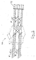
- Fig. 1 illustrates a preferred embodiment of an optical harness of the present invention, referred to generally as reference numeral 10.
- the optical harness 10 of the present invention provides an optical cross-connect capable of receiving multiple wavelengths and separating or mixing the wavelengths with accurately positioned optical fibers in a pre-designed configuration.
- the optical harness 10 transitions rows of a plurality of fibers 17, 19, disposed toward a first portion 12 of the optical harness 10, to a plurality of columns of fibers 21, 23, 25, disposed toward a second portion 14 of the harness 10, where the fibers have common positions in the rows.
- the present invention For receiving and re-routing M number of wavelengths, generally, the present invention embodies an optical harness 10 having a number M of fiber optic row cables 16 disposed toward a first portion 12 of an optical harness 10 and a number N of fiber optic column cables 18 disposed toward a second portion 14 of an optical harness 10.
- Each of the M number of fiber optic row cables 16 comprises an array comprising a number N of fiber optics arranged on a first plane that is substantially parallel to the first plane of each of the other M number of fiber optic row cables 16. It is preferable that each of the fiber optic row cables 16 is ribbonized, such as the type taught in U.S. Patent 4,900,126, the disclosure of which is herein incorporated by reference.
- Each of the N number of fiber optics is separated from its ribbonized configuration, re-routed, and configured such that each of the number N of fiber optic column cables 18 comprises an array of a number M of fibers.
- Each of the number M of fibers are arranged on a second plane substantially parallel to the second planes on which each of the other number N of fiber optic column cables 18 are arranged.
- each fiber optic in the array of the N number of fiber optics comprising each fiber optic row cable is re-routed to a different cable of the N number of fiber optic column cables.
- a holding and routing mechanism 20 is disposed intermediate first portion 12 and second portion 14 of the optical harness 10 and arranged and configured to maintain the fiber optic row cables 16 in the preferred first plane orientation and the fiber optic column cables 18 in the preferred second plane orientation.
- the fiber optics of the fiber optic column cables 18 can then be re-ribbonized in their new configuration. To provide a perfect shuffle cross-connect the fiber optics are re-routed in an organized manner.
- the optical fibers in a first position in each of the fiber optic row cables 16 can be re-routed to a first fiber optic column cable 18 and arranged "in order" such that the fiber re-routed from the first position fiber optic row cable is positioned as the first position fiber optic in the first position fiber optic column cable and the fiber optic re-routed from the second position fiber optic row cable is positioned as the second position fiber optic in the first position fiber optic column cable, and so on.
- the fibers can be coded, or marked, such as with color or by any other suitable means, to indicate their location in each fiber optic row cable (the fiber optic's position in an array). The fibers can be further marked to indicate from which fiber optic row cable the fiber optic originated.
- Fig. 1 illustrates a preferred embodiment of an optical harness 10 of the present invention.
- the optical harness 10 includes a first portion 12 and a second portion 14.
- the first position fiber optic row cable 17 comprises an array of fibers disposed in a first position fiber 31', preferably colored and marked, a second position fiber 32', preferably colored and marked, such as red R', and a third position fiber 33', preferably colored and marked, such as green G', arranged on a first plane.
- the second position fiber optic row cable 19 comprises a first position fiber 31'', preferably colored and marked, such as blue B'', a second position fiber 32'', preferably colored and marked, such as red R'', and a third position fiber 33'', preferably colored and marked G'', arranged preferably on a first plane.
- first position fiber optic row cable 17 and second position fiber optic row cable 19 are preferably ribbonized and collected by a holding mechanism 20. It is preferable that the first plane of the first fiber optic row cable 17 and the first plane of the second fiber optic row cable 19 are substantially parallel to each other.
- the fibers are arranged in columns of like colors.
- the fiber optics comprising the fiber optic row cables are separated from their respective originating fiber optic row cables 17, 19, and re-grouped and preferably re-ribbonized, into columns of like colors.
- the columns of like colors comprise the fiber optic column cables disposed toward the second portion 14 of the optical harness 10.
- the holding mechanism 20 holds the stack of fiber optic row cables in position and prevents the point of separation of the fibers out of the fiber optic row cable configuration from traveling further along the fiber optic row cables.
- the re-configured fiber optics extend from the holding mechanism 20 grouped in a first position fiber optic column cable 21, a second position fiber optic column cable 23 and a third position fiber optic column cable 25.
- the first position fiber optic column cable 21 preferably comprises the first position fiber optic 31', preferably colored and marked, such as in blue B', (from the first position fiber optic row cable 17) and the first position fiber optic 31'', preferably colored and marked, such as in blue B'', (from the second position fiber optic row cable 19), arranged on a second plane.
- the second position fiber optic column cable 23 comprises the second position fiber optic 32', preferably colored and marked, such as in red R', (from the first position fiber optic row cable 17) and the second position fiber optic 32'', preferably colored and marked, such as in red R'', (from the second position fiber optic row cable 19), arranged on a second plane.
- the third position fiber optic column cable 25 comprises the third position fiber optic 33', preferably colored and marked, such as in green G', (from the first position fiber optic row cable 17) and the third position fiber optic 33'', preferably colored and marked, such as in green G'', (from the second position fiber optic row cable 19), arranged on a second plane.
- the first position for each of the fiber optic column cables originate from the first position fiber optic row cable 17.
- the second position fiber optics 31'', 32'' and 33'', marked B'', R'', and G'', respectively are in the second position of each of the fiber optic column cables.
- each fiber optic row cable 17, 19 is in communication with each fiber optic column cable 21, 23, 25 by one fiber optic.
- This method of reconfiguration provides for the perfect shuffle cross-connect.
- marking each fiber optic to indicate its location at the first portion 12 of the optical harness 10 can assist in such an organized re-routing.
- each of the fiber optic row cables 17, 19 are preferably arranged and held by the holding mechanism 20 on a first plane, each first plane being substantially parallel to the others.
- each of the fiber optic column cables 21, 23, 25 are preferably arranged and held by the holding mechanism 20 on a second plane, each second plane being substantially parallel to the others.
- the first planes on which the fiber optic row cables are arranged are preferably oriented at a defined angle relative to the second planes on which the fiber optic column cables are arranged. The defined angle can be substantially ninety degrees.
- opposing free ends of the fiber optic row cables and fiber optic column cables, respectively can further include connectors 42, such as an optical array connector taught in U.S. Patent 5,214,730, the disclosure of which is herein incorporated by reference, suitable for communicating with other elements between which the perfect shuffle cross-connection is desired.
- M number of fiber optic row cables are provided.
- Each of the fiber optic row cables can be connectorized at only one end.
- Each of the fiber optic row cables comprises an array of N number of fiber optics, preferably each of the N number of fiber optics is marked with a different color, or other suitable marking, and arranged in the same order within each of the cables.
- the cables are stacked one on top of each other such that corresponding colors (or other marking) of fibers are disposed on top of each other in a column and that all of the connectorized ends are on the same side of the stack.
- the M number of fiber optic row cables can be cut from the same reel of ribbon cable.
- the stack of fiber optic row cables can be secured in this configuration preferably intermediate the connectorized ends and the non-connectorized ends.
- the non-connectorized end is preferably cut at an oblique angle such that the fibers at one end and marked of a like color or other marking, such as the blue marked fibers B, are longer than the fibers disposed beside them, such as the red marked fibers R, in the fiber optic row cable configuration.
- the columns of like colored fibers can then be separated from their original respective row configurations and re-ribbonized into like marked fiber optic column cables.
- the harness 10 can be turned such that the columns of like colored fibers are flush with a flat surface, such as a table top. Secondary markings on the fibers can help when re-grouping to keep the fibers in proper order.
- optical harness and optical cross-connect providing a perfect shuffle is disclosed herein in detail, one with ordinary skill in the art will appreciate that the present disclosure can include other specific optical cross-connects. It should further be noted that while in some optical cross-connects the number N and number M may differ; in several other cases the number N and number M may be the same. It is intended that all such variations are within the spirit of the present invention.
Landscapes
- Physics & Mathematics (AREA)
- General Physics & Mathematics (AREA)
- Optics & Photonics (AREA)
- Light Guides In General And Applications Therefor (AREA)
- Mechanical Coupling Of Light Guides (AREA)
Abstract
Description
- Advances in light wave technology have made optical fibers a very popular medium for large bandwidth communication applications. In particular, optical technology is being utilized more and more in broadband systems wherein communications between systems take place on high-speed optical channels. As this trend continues to gain more and more momentum, the need for efficient utilization of the precious real estate on circuit boards, racks/shelves, back planes, distribution cabinets, etc., is becoming ever increasingly important. In order to fulfill expectations across the industry, opto-electronic modules and optic fiber devices need to continue to be made miniaturized or compact, thereby taking full advantage of the maturity of micro- and opto-electronic technologies for generating, transporting, managing and delivering broadband services to ever increasing bandwidth demands of end users at increasingly lower costs. Thus, the industry has placed an emphasis on small optical connectors and optical harnesses, both simple and complex. However, miniaturizing and compacting is tempered by the requirements of transmission efficiency and organization.
- With the miniaturization of optical modules and optical fiber devices, the management of optical fiber congestion has become an issue at optical interfaces and connection distribution points. One solution is the use of multi-fiber ribbon in which a plurality of optical fibers are organized and contained side by side in a plastic ribbon. It is known to interconnect these ribbon cables by supporting the fibers between two support members made of a monocrystaline material, such as silicon. In the support members are V-grooves formed utilizing photolithographic masking and etching techniques. The fibers are placed side by side in individual V-grooves of one support member and the other mating support member having corresponding V-grooves is placed over the fibers so as to bind or hold the fibers in a high precision spatial relationship between the mating V-grooves. The top and bottom support members sandwiching the multi-fiber ribbon are typically bonded together with a clamp or adhesive, forming a plug of a multi-fiber connector. Two mating plugs with the same fiber spacing may then be placed in an abutting relationship so that the ends of the fibers of the respective plugs are substantially co-axially aligned with one another, thereby forming a multi-fiber connection. If desired, such plugs can be stacked in order to increase the interconnection density. However, in addition to straight connections, in some applications it is desirable to re-route the optical fibers in a multi-fiber ribbon and reconfigure the optical fibers in a new multi-fiber ribbon combination.
- Multi-fiber ribbons and connectors have numerous applications in optic communication systems. For instance, optical switches, optical power splitters/combiners routers, etc., have several input and/or output ports arranged as linear arrays to which a plurality of fibers are to be coupled. Further, since optical fibers are attached somehow to launch optical signals into these devices and extract optical signals therefrom, splicing of arrays of fibers (i.e., a multi-fiber ribbon) to such devices can be achieved using multi-fiber connectors. Another possible application relates to an optical fan-out fabric where an array of fibers in a multi-fiber ribbon may be broken into simplex or duplex channels for distribution purposes, as is often desired.
- Another multiple fiber application is the perfect shuffle cross-connect, where, for example, each of the multiple input ports, typically comprising more than one optical fiber, is in communication by one fiber with each of the multiple output ports, which also typically comprises more than one optical fiber. The perfect shuffle cross-connect provides for multi-channel optical transmissions, for example as in multi-wavelength transmissions, to be mixed in an orderly fashion. Currently, such connections are made by flexible optical circuits or complex jumpers. While complex jumpers take up space and create congestion, the flexible optical circuit is expensive to produce, often requiring highly skilled labor, such as a CAD designer to generate the original drawings of the circuit, and expensive processing machines such as those for fiber routing, lamination and connectorization equipment.
- In summary, there continues to be strong market forces driving the development of fiber optic connection systems that take up less space and relieve congestion, while at the same time demanding that the increasing interconnection density requirements be satisfied. Further, such a connection system should be capable of being manufactured and assembled easily and inexpensively.
- Thus, a heretofore unaddressed need exists in the industry to address the aforementioned deficiencies and inadequacies.
- The present invention is an optical harness for an optical cross-connect defined primarily by a first portion and a second portion. The first portion of the optical harness comprises a number M of fiber optic row cables where each fiber optic row cable comprises an array of a number N of fibers arranged on a first plane. The first plane on which each fiber optic row cable is disposed is substantially parallel to each other first plane on which a fiber optic row cable is disposed. The second portion of the optical harness comprises a number N of fiber optic column cables where each fiber optic column cable comprises an array of a number M of fibers arranged on a second plane angularly disposed relative to the first plane. The second plane on which each fiber optic column cable is disposed is substantially parallel to each other second plane on which a fiber optic column cable is disposed. The optical harness further comprises a holding mechanism disposed intermediate the first portion and the second portion of the optical harness. The orientation of the first planes on which the fiber optic row cables are disposed is arranged at a defined angle relative to the second planes on which the fiber optic column cables are disposed. The holding mechanism is arranged and configured to transition the fibers from one configuration toward the first portion to the other configuration toward the second portion and to maintain the relative angled arrangement.
- The present invention can also be viewed as a method for providing an optical cross-connect between a first element and a second element between which distribution or re-routing accurately positioned optical fibers in predetermined configuration is desired. In this regard, the method can be broadly summarized by the following steps: providing a number M of fiber optic row cables having a defined length, where each fiber optic row cable comprises an array of a number N of fibers arranged on a first plane substantially parallel to the first plane of each of the other fiber optic row cables; stacking the number M of fiber optic row cables; disposing a holding mechanism intermediate the defined length of the fiber optic row cables; separating each array of N fibers into individual fibers; re-grouping the fiber optics into a number N of fiber optic column cables, each comprising a number M of fibers; connecting the first portion of the cross-connect to the first element; and connecting the second portion of the cross-connect to the second element. Thus a transition from a plurality, such as twelve, rows of, for example, ten fibers each, to an array of ten columns of twelve fibers each is realized. Each column contains only the fibers which have common positions in the rows. Thus all number one fibers are in one column, number two fibers in a second column, etc. This makes possible a perfect shuffle cross-connect in a minimum of space and complexity.
- Other features and advantages of the present invention will become apparent to one with skill in the art upon examination of the following drawings and detailed description. It is intended that all such additional features and advantages be included herein within the scope of the present invention.
- The invention can be better understood with reference to the following drawings. The components in the drawings are not necessarily to scale, emphasis instead being placed upon clearly illustrating the principles of the present invention. Moreover, in the drawings, like reference numerals designate corresponding parts throughout the several views.
- FIG. 1 illustrates a perspective view of the present invention.
- FIG. 2 illustrates a perspective view showing a cut-away view of the holding mechanism of the optical harness of FIG. 1.
-
- While the invention is susceptible to various modifications and alternative forms, a specific embodiment thereof is shown by way of example in the drawings and will herein be described in detail. It should be understood, however, that there is no intent to limit the invention to the particular form disclosed, but on the contrary, the invention is to cover all modification, equivalents, and alternatives falling within the spirit and scope of the invention as defined by the claims.
- Fig. 1 illustrates a preferred embodiment of an optical harness of the present invention, referred to generally as reference numeral 10. The optical harness 10 of the present invention provides an optical cross-connect capable of receiving multiple wavelengths and separating or mixing the wavelengths with accurately positioned optical fibers in a pre-designed configuration. Broadly, the optical harness 10 transitions rows of a plurality of
fibers 17, 19, disposed toward afirst portion 12 of the optical harness 10, to a plurality of columns offibers second portion 14 of the harness 10, where the fibers have common positions in the rows. - For receiving and re-routing M number of wavelengths, generally, the present invention embodies an optical harness 10 having a number M of fiber
optic row cables 16 disposed toward afirst portion 12 of an optical harness 10 and a number N of fiberoptic column cables 18 disposed toward asecond portion 14 of an optical harness 10. Each of the M number of fiberoptic row cables 16 comprises an array comprising a number N of fiber optics arranged on a first plane that is substantially parallel to the first plane of each of the other M number of fiberoptic row cables 16. It is preferable that each of the fiberoptic row cables 16 is ribbonized, such as the type taught in U.S. Patent 4,900,126, the disclosure of which is herein incorporated by reference. Each of the N number of fiber optics is separated from its ribbonized configuration, re-routed, and configured such that each of the number N of fiberoptic column cables 18 comprises an array of a number M of fibers. Each of the number M of fibers are arranged on a second plane substantially parallel to the second planes on which each of the other number N of fiberoptic column cables 18 are arranged. To re-rout the multiple wavelengths in a predetermined accurate configuration, or provide a perfect shuffle optical cross-connect, each fiber optic in the array of the N number of fiber optics comprising each fiber optic row cable is re-routed to a different cable of the N number of fiber optic column cables. A holding androuting mechanism 20 is disposed intermediatefirst portion 12 andsecond portion 14 of the optical harness 10 and arranged and configured to maintain the fiberoptic row cables 16 in the preferred first plane orientation and the fiberoptic column cables 18 in the preferred second plane orientation. The fiber optics of the fiberoptic column cables 18 can then be re-ribbonized in their new configuration. To provide a perfect shuffle cross-connect the fiber optics are re-routed in an organized manner. For example, the optical fibers in a first position in each of the fiberoptic row cables 16 can be re-routed to a first fiberoptic column cable 18 and arranged "in order" such that the fiber re-routed from the first position fiber optic row cable is positioned as the first position fiber optic in the first position fiber optic column cable and the fiber optic re-routed from the second position fiber optic row cable is positioned as the second position fiber optic in the first position fiber optic column cable, and so on. To assist in ensuring such organization, the fibers can be coded, or marked, such as with color or by any other suitable means, to indicate their location in each fiber optic row cable (the fiber optic's position in an array). The fibers can be further marked to indicate from which fiber optic row cable the fiber optic originated. - More specifically, Fig. 1 illustrates a preferred embodiment of an optical harness 10 of the present invention. The optical harness 10 includes a
first portion 12 and asecond portion 14. Looking first at thefirst portion 12, the first position fiber optic row cable 17 comprises an array of fibers disposed in a first position fiber 31', preferably colored and marked, a second position fiber 32', preferably colored and marked, such as red R', and a third position fiber 33', preferably colored and marked, such as green G', arranged on a first plane. Similarly, the second position fiberoptic row cable 19 comprises a first position fiber 31'', preferably colored and marked, such as blue B'', a second position fiber 32'', preferably colored and marked, such as red R'', and a third position fiber 33'', preferably colored and marked G'', arranged preferably on a first plane. Although two fiber optic row cables comprising three fibers each are illustrated, it should be understood that the present invention can include any number of fiber optic row cables each comprising any number of fibers. The first position fiber optic row cable 17 and second position fiberoptic row cable 19 are preferably ribbonized and collected by aholding mechanism 20. It is preferable that the first plane of the first fiber optic row cable 17 and the first plane of the second fiberoptic row cable 19 are substantially parallel to each other. In this stacked configuration, the fibers are arranged in columns of like colors. The fiber optics comprising the fiber optic row cables are separated from their respective originating fiberoptic row cables 17, 19, and re-grouped and preferably re-ribbonized, into columns of like colors. The columns of like colors comprise the fiber optic column cables disposed toward thesecond portion 14 of the optical harness 10. The holdingmechanism 20 holds the stack of fiber optic row cables in position and prevents the point of separation of the fibers out of the fiber optic row cable configuration from traveling further along the fiber optic row cables. The re-configured fiber optics extend from the holdingmechanism 20 grouped in a first position fiberoptic column cable 21, a second position fiber optic column cable 23 and a third position fiberoptic column cable 25. The first position fiberoptic column cable 21 preferably comprises the first position fiber optic 31', preferably colored and marked, such as in blue B', (from the first position fiber optic row cable 17) and the first position fiber optic 31'', preferably colored and marked, such as in blue B'', (from the second position fiber optic row cable 19), arranged on a second plane. Similarly, the second position fiber optic column cable 23 comprises the second position fiber optic 32', preferably colored and marked, such as in red R', (from the first position fiber optic row cable 17) and the second position fiber optic 32'', preferably colored and marked, such as in red R'', (from the second position fiber optic row cable 19), arranged on a second plane. Finally, the third position fiberoptic column cable 25 comprises the third position fiber optic 33', preferably colored and marked, such as in green G', (from the first position fiber optic row cable 17) and the third position fiber optic 33'', preferably colored and marked, such as in green G'', (from the second position fiber optic row cable 19), arranged on a second plane. - It should be noted that the first position for each of the fiber optic column cables, the first position optic fiber 31', 32' and 33', marked B', R' and G' respectively, originate from the first position fiber optic row cable 17. Similarly, the second position fiber optics 31'', 32'' and 33'', marked B'', R'', and G'', respectively, are in the second position of each of the fiber optic column cables. As such, each fiber
optic row cable 17, 19 is in communication with each fiberoptic column cable first portion 12 of the optical harness 10 can assist in such an organized re-routing. - Each of the fiber
optic row cables 17, 19 are preferably arranged and held by the holdingmechanism 20 on a first plane, each first plane being substantially parallel to the others. Likewise, each of the fiberoptic column cables mechanism 20 on a second plane, each second plane being substantially parallel to the others. The first planes on which the fiber optic row cables are arranged are preferably oriented at a defined angle relative to the second planes on which the fiber optic column cables are arranged. The defined angle can be substantially ninety degrees. To provide a perfect shuffle cross-connect communication, opposing free ends of the fiber optic row cables and fiber optic column cables, respectively, can further includeconnectors 42, such as an optical array connector taught in U.S. Patent 5,214,730, the disclosure of which is herein incorporated by reference, suitable for communicating with other elements between which the perfect shuffle cross-connection is desired. - In a preferred method of assembly, M number of fiber optic row cables are provided. Each of the fiber optic row cables can be connectorized at only one end. Each of the fiber optic row cables comprises an array of N number of fiber optics, preferably each of the N number of fiber optics is marked with a different color, or other suitable marking, and arranged in the same order within each of the cables. The cables are stacked one on top of each other such that corresponding colors (or other marking) of fibers are disposed on top of each other in a column and that all of the connectorized ends are on the same side of the stack. For the sake of uniformity, the M number of fiber optic row cables can be cut from the same reel of ribbon cable. The stack of fiber optic row cables can be secured in this configuration preferably intermediate the connectorized ends and the non-connectorized ends. The non-connectorized end is preferably cut at an oblique angle such that the fibers at one end and marked of a like color or other marking, such as the blue marked fibers B, are longer than the fibers disposed beside them, such as the red marked fibers R, in the fiber optic row cable configuration. The columns of like colored fibers can then be separated from their original respective row configurations and re-ribbonized into like marked fiber optic column cables. To facilitate separation of the fibers from the ribbonized row configurations, the harness 10 can be turned such that the columns of like colored fibers are flush with a flat surface, such as a table top. Secondary markings on the fibers can help when re-grouping to keep the fibers in proper order.
- Although an optical harness and optical cross-connect providing a perfect shuffle is disclosed herein in detail, one with ordinary skill in the art will appreciate that the present disclosure can include other specific optical cross-connects. It should further be noted that while in some optical cross-connects the number N and number M may differ; in several other cases the number N and number M may be the same. It is intended that all such variations are within the spirit of the present invention.
Claims (27)
- An optical harness having a first portion and a second portion, said optical harness comprising:a number M of fiber optic row cables, each of said fiber optic row cables comprising an array of a number N of fibers arranged on a first plane, said fiber optic row cables being disposed toward said first portion of said optical harness, said first plane of each fiber optic row cable being substantially parallel to each other first plane;a number N of fiber optic column cables, each of said fiber optic column cables comprising an array of a number M of fiber optics arranged on a second plane, said fiber optic column cables being disposed toward said second portion of said optical harness, said second plane of each fiber optic column cable being substantially parallel to each other second plane; anda holding mechanism disposed intermediate said first portion and said second portion of said optical harness;
wherein said first plane is oriented at a defined angle relative to said second plane and said holding mechanism is arranged and configured to transition said fiber optics from said first portion to said second portion and to maintain said orientation. - The optical harness of claim 1, wherein said N number of fiber optics comprising each of said M number of fiber optic row cables is reconfigured to provide an optical cross-connect.
- The optical harness of claim 2, wherein said optical cross-connect comprises a perfect shuffle.
- The optical harness of claim 1, wherein each of said N number of fiber optics in each of said fiber optic row cables is re-routed to a different of said N number of fiber optic column cables.
- The optical harness of claim 1, further comprising:a number M of connectors disposed at said first portion of said optical harness, wherein each of said fiber optic row cables supports one connector;a number N of connectors disposed at said second portion of said optical harness, wherein each of said fiber optic column cables supports one connector; and
wherein each of said M number of connectors is in communication with each of said N number of connectors by one fiber optic. - The optical harness of claim 1, wherein the number M is equal to the number N.
- The optical harness of claim 1, wherein the number M is different from the number N.
- The optical harness of claim 1, wherein each of said fiber optic column cables is ribbonized.
- The optical harness of claim 1, wherein each of said fiber optic row cables is ribbonized.
- The optical harness of claim 1, wherein each of said fiber optics is primarily coded to indicate the position in which each optical fiber is disposed within each of said optical fiber row cables.
- The optical harness of claim 10, wherein each of said fiber optics is secondarily coded to indicate in which optical fiber row cable each fiber optic is arranged.
- The optical harness of claim 1, wherein said defined angle comprises substantially ninety degrees.
- A method for assembling an optical harness having a first portion and a second portion, said method comprising the steps of:providing a number M of fiber optic row cables, each of said fiber optic row cables comprising a number N of fiber optics, said fiber optic row cables being disposed toward said first portion of said optical harness;providing a number N of fiber optic column cables, each of said fiber optic column cables comprising a number M of fiber optics, said fiber optic column cables being disposed toward said second portion of said optical harness; anddisposing a holding mechanism intermediate said first portion and said second portion of said optical harness, wherein said holding mechanism is arranged and configured to transition said fiber optics from said first portion to said second portion and to maintain said orientation;orienting said fiber optic column cables at a defined angle relative to said fiber optic row cables.
- The method of claim 13, wherein said N number of fiber optics comprising each of said M number of fiber optic row cables is reconfigured to provide an optical cross-connect.
- The method of claim 14, wherein said optical cross-connect comprises a perfect shuffle.
- The method of claim 13, wherein each of said N number of fiber optics in each of said fiber optic row cables is re-routed to a different of said N number of fiber optic column cables.
- The method of claim 13, wherein said fiber optic row cables have a fixed end and a free end and said fiber optic column cables have a fixed end and a free end, said method further comprising the steps of:fixing M number of connectors to said free end of said fiber optic row cables, wherein one connector is fixed to said free end of each of said M number of said fiber optic row cables; andfixing N number of connectors to said free end of said fiber optic column cables, wherein one connector is fixed to said free end of each of said N number of fiber optic column cables;
wherein each of said M number of connectors is in communication with each of said N number of connectors by one fiber optic. - The method of claim 13, wherein the number M is equal to the number N.
- The method of claim 13, wherein the number M is different from the number N.
- The method of claim 13, further comprising the step of:primarily marking each of said fiber optics to indicate the position in which each optical fiber is disposed within each of said optical fiber row cables.
- The method of claim 20, further comprising the step of:secondarily marking each of said fiber optics to indicate in which fiber optic row cable each fiber optic is arranged.
- The method of claim 13, wherein said defined angle comprises substantially ninety degrees.
- A method for cross-connecting between a first element and a second element said method comprising the steps of:providing a number M of fiber optic row cables having a first end and a second end, each of said fiber optic row cables having a number N of fiber optics arranged on a first plane;connectorizing said first end of each of said number M of fiber optic row cables;stacking said number M of fiber optic row cables such that said connectorized ends of said fiber optic row cables are grouped together;fixing said stack of fiber optic row cables together;separating said number N of fiber optics in each of said number M of fiber optic row cables;grouping said number N of fiber optics into number N of fiber optic column cables each comprising number M of fiber optics, said fiber optic column cables being arranged on a second plane, wherein said second plane is arranged at a predetermined angle with respect to said first plane;connectorizing said second end;connecting said first end to said first element; andconnecting said second end to said second element.
- The method of claim 23, wherein said defined angle is substantially ninety degrees.
- The method of claim 23, wherein said cross-connecting comprises a perfect shuffle.
- An optical harness comprising a number M of optical ribbon cables that extend longitudinally between first and second ends of the harness, each of said ribbon cables comprising a number N of optical fibers that are held together as a unit in a planar array
CHARACTERIZED BYa number M of optical array connectors disposed at the first end of the optical harness, wherein each of the optical ribbon cables terminates in one of said M number of array connectors; anda number N of optical array connectors disposed at the second end of the optical harness, wherein one optical fiber from each of the ribbon cables terminates in one of said N number of array connectors. - The optical harness of claim 26, wherein the interconnection of optical fibers between the connectors at the first and second ends of the harness comprises a perfect shuffle.
Applications Claiming Priority (2)
| Application Number | Priority Date | Filing Date | Title |
|---|---|---|---|
| US09/343,967 US6222976B1 (en) | 1999-06-30 | 1999-06-30 | Optical harness and cross-connect method |
| US343967 | 1999-06-30 |
Publications (2)
| Publication Number | Publication Date |
|---|---|
| EP1065544A2 true EP1065544A2 (en) | 2001-01-03 |
| EP1065544A3 EP1065544A3 (en) | 2002-02-13 |
Family
ID=23348448
Family Applications (1)
| Application Number | Title | Priority Date | Filing Date |
|---|---|---|---|
| EP00305212A Withdrawn EP1065544A3 (en) | 1999-06-30 | 2000-06-20 | Optical harness and cross-connect method |
Country Status (3)
| Country | Link |
|---|---|
| US (1) | US6222976B1 (en) |
| EP (1) | EP1065544A3 (en) |
| JP (1) | JP2001042136A (en) |
Cited By (15)
| Publication number | Priority date | Publication date | Assignee | Title |
|---|---|---|---|---|
| EP1124147A2 (en) * | 2000-02-08 | 2001-08-16 | Lucent Technologies Inc. | Optical coupler with optical connector and cross-connect method |
| EP1182484A2 (en) * | 2000-08-15 | 2002-02-27 | F.C.I. - Framatome Connectors International | Optical fiber separation and regrouping device |
| US6690867B2 (en) | 2001-08-31 | 2004-02-10 | Corning Cable Systems Llc | Optical interconnect assemblies and methods therefor |
| EP1546780A2 (en) * | 2002-09-27 | 2005-06-29 | Corning Cable Systems LLC | Optical polarity modules and systems |
| US7689079B2 (en) | 2008-01-11 | 2010-03-30 | Corning Cable Systems Llc | Optical fiber interconnection devices and systems using same |
| WO2014018428A1 (en) * | 2012-07-25 | 2014-01-30 | Corning Cable Systems Llc | Polarity scheme for parallel-optics data transmission |
| DE102012020590A1 (en) | 2012-10-22 | 2014-04-24 | Reichle + De-Massari Ag | connecting device |
| DE102013102853A1 (en) | 2013-03-20 | 2014-09-25 | Reichle + De-Massari Ag | connecting device |
| US8873967B2 (en) | 2008-10-17 | 2014-10-28 | Corning Cable Systems Llc | Optical interconnection modules for hybrid electrical-optical networks |
| DE102013105058A1 (en) | 2013-05-16 | 2014-11-20 | Reichle & De-Massari Ag | connecting device |
| US9097874B2 (en) | 2012-07-25 | 2015-08-04 | Corning Optical Communications LLC | Polarity configurations for parallel optics data transmission, and related apparatuses, components, systems, and methods |
| US9097873B2 (en) | 2010-04-14 | 2015-08-04 | Corning Cable Systems Llc | Port mapping in fiber optic network devices |
| US9207421B2 (en) | 2008-10-14 | 2015-12-08 | Corning Cable Systems Llc | Fiber optic network architecture having optical connection terminals in series arrangement |
| US9229175B2 (en) | 2009-06-17 | 2016-01-05 | Corning Cable Systems Llc | Optical interconnection assemblies and systems for high-speed data-rate optical transport systems |
| US9482840B2 (en) | 2009-05-27 | 2016-11-01 | Corning Cable Systems Llc | Port mapping for series connected fiber optic terminals |
Families Citing this family (35)
| Publication number | Priority date | Publication date | Assignee | Title |
|---|---|---|---|---|
| US6464404B1 (en) * | 2000-06-19 | 2002-10-15 | Schott Fiber Optics, Inc. | Optical fiber rearrangement method and device |
| US6498882B1 (en) * | 2000-11-28 | 2002-12-24 | Lightwave Microsystems Corporation | Assembly and method for reorganizing planar lightwave circuit channels |
| WO2002057829A1 (en) * | 2001-01-17 | 2002-07-25 | The Whitaker Corporation | Optical cross connect |
| US6850684B2 (en) | 2001-08-10 | 2005-02-01 | 3M Innovative Properties Company | Three dimensional optical circuits |
| US6556754B2 (en) | 2001-08-10 | 2003-04-29 | 3M Innovative Properties Company | Three dimensional optical circuit |
| US6538207B1 (en) | 2002-01-18 | 2003-03-25 | Agilent Technologies, Inc. | Strain relief structures for lead connections |
| US6763166B2 (en) | 2002-08-22 | 2004-07-13 | Corning Calde Systems Llc | Flexible shuffle circuit and method for assembling same |
| US6775458B2 (en) * | 2002-08-22 | 2004-08-10 | Corning Cable Systems Llc | Fixture for a flexible shuffle circuit |
| US7120349B2 (en) * | 2002-10-29 | 2006-10-10 | Hewlett-Packard Development Company, L.P. | Fiber optic cable device with retractable operation |
| US6947655B2 (en) * | 2003-02-05 | 2005-09-20 | Schott Corporation | Ruggedized optical fiber rearrangement device |
| US7184635B2 (en) * | 2004-06-04 | 2007-02-27 | Commscope Solutions Properties, Llc | Optical fiber array connectivity system utilizing angle polished ferrules and aligned-key adapters and cable for same |
| US7416347B2 (en) * | 2005-05-31 | 2008-08-26 | Commscope Solutions Properties, Llc | Optical fiber array connectivity system with indicia to facilitate connectivity in four orientations for dual functionality |
| US7362936B2 (en) * | 2006-03-01 | 2008-04-22 | Defense Photonics Group, Inc. | Optical harness assembly and method |
| US8596879B2 (en) | 2011-08-19 | 2013-12-03 | International Business Machines Corporation | Method to reorder (shuffle) optical cable waveguide layers |
| US9417418B2 (en) | 2011-09-12 | 2016-08-16 | Commscope Technologies Llc | Flexible lensed optical interconnect device for signal distribution |
| US9535229B2 (en) | 2011-10-07 | 2017-01-03 | Commscope Technologies Llc | Fiber optic cassette, system, and method |
| US9146374B2 (en) | 2012-09-28 | 2015-09-29 | Adc Telecommunications, Inc. | Rapid deployment packaging for optical fiber |
| BR112015007015B1 (en) | 2012-09-28 | 2022-10-11 | Tyco Electronics Nederland Bv | FIBER OPTIC CASSETTE TAPE, METHOD FOR ASSEMBLING A FIBER OPTIC CASSETTE TAPE AND FLEXIBLE OPTICAL CIRCUIT |
| US9223094B2 (en) | 2012-10-05 | 2015-12-29 | Tyco Electronics Nederland Bv | Flexible optical circuit, cassettes, and methods |
| US9468085B2 (en) | 2012-12-29 | 2016-10-11 | Zephyr Photonics Inc. | Method and apparatus for implementing optical modules in high temperatures |
| US9190809B2 (en) | 2012-12-29 | 2015-11-17 | Zephyr Photonics Inc. | Method and apparatus for active voltage regulation in optical modules |
| US9160452B2 (en) | 2012-12-29 | 2015-10-13 | Zephyr Photonics Inc. | Apparatus for modular implementation of multi-function active optical cables |
| US10958348B2 (en) | 2012-12-29 | 2021-03-23 | Zephyr Photonics Inc. | Method for manufacturing modular multi-function active optical cables |
| US9728936B2 (en) | 2012-12-29 | 2017-08-08 | Zephyr Photonics Inc. | Method, system and apparatus for hybrid optical and electrical pumping of semiconductor lasers and LEDs for improved reliability at high temperatures |
| US9172462B2 (en) | 2012-12-31 | 2015-10-27 | Zephyr Photonics Inc. | Optical bench apparatus having integrated monitor photodetectors and method for monitoring optical power using same |
| US9435975B2 (en) | 2013-03-15 | 2016-09-06 | Commscope Technologies Llc | Modular high density telecommunications frame and chassis system |
| US9535230B2 (en) | 2014-01-31 | 2017-01-03 | Senko Advanced Components, Inc. | Integrated fiber optic cable fan-out connector |
| JP2017187678A (en) * | 2016-04-07 | 2017-10-12 | 住友電気工業株式会社 | Optical wiring member |
| EP3692404A4 (en) | 2017-10-02 | 2021-06-16 | Commscope Technologies LLC | Fiber optic circuit and preparation method |
| CN112074995A (en) | 2018-04-02 | 2020-12-11 | 扇港元器件股份有限公司 | Hybrid anti-penetration connector and adapter assembly |
| JP6691164B2 (en) * | 2018-04-04 | 2020-04-28 | 矢崎総業株式会社 | Branching circuit body and wire branching method |
| JP6644824B2 (en) * | 2018-04-04 | 2020-02-12 | 矢崎総業株式会社 | Branch circuit body and branching method of electric wire |
| CN114930215B (en) * | 2020-02-18 | 2024-04-12 | 住友电气工业株式会社 | Optical fiber connection structure with optical connector and module |
| WO2022240838A1 (en) * | 2021-05-13 | 2022-11-17 | Commscope Technologies Llc | Shuffle cable |
| WO2023195969A1 (en) * | 2022-04-04 | 2023-10-12 | Corning Research & Development Corporation | Cable assembly design tool with fiber utilization counter |
Citations (5)
| Publication number | Priority date | Publication date | Assignee | Title |
|---|---|---|---|---|
| EP0378235A2 (en) * | 1989-01-12 | 1990-07-18 | Sumitomo Electric Industries, Ltd. | Optical fiber wiring apparatus |
| JPH06332019A (en) * | 1993-05-26 | 1994-12-02 | Fujitsu Ltd | Circuit for connection between switch modules of spatial optical switch |
| JPH07318737A (en) * | 1994-05-27 | 1995-12-08 | Oki Electric Ind Co Ltd | Optical network |
| US5620634A (en) * | 1995-08-17 | 1997-04-15 | Lucent Technologies Inc. | Method of making fiber waveguide connectors |
| EP0853440A2 (en) * | 1996-12-27 | 1998-07-15 | Nippon Telegraph And Telephone Corporation | Optical cross-connect system |
Family Cites Families (11)
| Publication number | Priority date | Publication date | Assignee | Title |
|---|---|---|---|---|
| US5155785A (en) * | 1991-05-01 | 1992-10-13 | At&T Bell Laboratories | Optical fiber interconnection apparatus and method |
| US5134673A (en) * | 1991-05-10 | 1992-07-28 | At&T Bell Laboratories | Optical fiber array splicing device |
| US5222179A (en) * | 1992-03-02 | 1993-06-22 | Porta Systems Corp. | Means for routing ribbon type fiber optic cable |
| US5239609A (en) * | 1992-03-03 | 1993-08-24 | Porta Systems Corp. | Means for routing buffer tube type fiber optical cable |
| US5367595A (en) * | 1993-07-15 | 1994-11-22 | General Motors Corporation | Fiber optic connector for connecting a fiber optic harness to an optical device |
| US5394502A (en) * | 1993-12-21 | 1995-02-28 | United Technologies Corporation | Fiber optic cable harness break-out fitting |
| US5381501A (en) * | 1994-01-27 | 1995-01-10 | General Motors Corporation | Fiber optic bundle connector including a hollow cone and a terminal block |
| US5734777A (en) * | 1996-06-18 | 1998-03-31 | Siecor Corporation | Strain relief device for plurality of optical ribbon fibers |
| US5926598A (en) * | 1997-06-10 | 1999-07-20 | Klein; Dennis | Apparatus for breaking out ribbonized fiber optic cables |
| US6034821A (en) * | 1997-09-05 | 2000-03-07 | Nec Research Institute, Inc. | Optomechanical components for use as optical interconnects |
| US6148134A (en) * | 1999-03-25 | 2000-11-14 | Schoonscan, Inc. | Fiber mounts for fiber optic harness in a fiber optic-based imaging system |
-
1999
- 1999-06-30 US US09/343,967 patent/US6222976B1/en not_active Expired - Fee Related
-
2000
- 2000-06-20 EP EP00305212A patent/EP1065544A3/en not_active Withdrawn
- 2000-06-30 JP JP2000199725A patent/JP2001042136A/en active Pending
Patent Citations (5)
| Publication number | Priority date | Publication date | Assignee | Title |
|---|---|---|---|---|
| EP0378235A2 (en) * | 1989-01-12 | 1990-07-18 | Sumitomo Electric Industries, Ltd. | Optical fiber wiring apparatus |
| JPH06332019A (en) * | 1993-05-26 | 1994-12-02 | Fujitsu Ltd | Circuit for connection between switch modules of spatial optical switch |
| JPH07318737A (en) * | 1994-05-27 | 1995-12-08 | Oki Electric Ind Co Ltd | Optical network |
| US5620634A (en) * | 1995-08-17 | 1997-04-15 | Lucent Technologies Inc. | Method of making fiber waveguide connectors |
| EP0853440A2 (en) * | 1996-12-27 | 1998-07-15 | Nippon Telegraph And Telephone Corporation | Optical cross-connect system |
Non-Patent Citations (2)
| Title |
|---|
| PATENT ABSTRACTS OF JAPAN vol. 1995, no. 03, 28 April 1995 (1995-04-28) -& JP 06 332019 A (FUJITSU LTD), 2 December 1994 (1994-12-02) * |
| PATENT ABSTRACTS OF JAPAN vol. 1996, no. 04, 30 April 1996 (1996-04-30) -& JP 07 318737 A (OKI ELECTRIC IND CO LTD), 8 December 1995 (1995-12-08) * |
Cited By (24)
| Publication number | Priority date | Publication date | Assignee | Title |
|---|---|---|---|---|
| EP1124147A2 (en) * | 2000-02-08 | 2001-08-16 | Lucent Technologies Inc. | Optical coupler with optical connector and cross-connect method |
| EP1124147A3 (en) * | 2000-02-08 | 2002-02-13 | Lucent Technologies Inc. | Optical coupler with optical connector and cross-connect method |
| EP1182484A2 (en) * | 2000-08-15 | 2002-02-27 | F.C.I. - Framatome Connectors International | Optical fiber separation and regrouping device |
| EP1182484A3 (en) * | 2000-08-15 | 2004-06-09 | F.C.I. - Framatome Connectors International | Optical fiber separation and regrouping device |
| US6690867B2 (en) | 2001-08-31 | 2004-02-10 | Corning Cable Systems Llc | Optical interconnect assemblies and methods therefor |
| EP1546780A4 (en) * | 2002-09-27 | 2006-07-26 | Corning Cable Sys Llc | Optical polarity modules and systems |
| EP2259118A3 (en) * | 2002-09-27 | 2011-02-23 | Corning Cable Systems LLC | Optical polarity modules and systems |
| EP1546780A2 (en) * | 2002-09-27 | 2005-06-29 | Corning Cable Systems LLC | Optical polarity modules and systems |
| US7689079B2 (en) | 2008-01-11 | 2010-03-30 | Corning Cable Systems Llc | Optical fiber interconnection devices and systems using same |
| US9207421B2 (en) | 2008-10-14 | 2015-12-08 | Corning Cable Systems Llc | Fiber optic network architecture having optical connection terminals in series arrangement |
| US8873967B2 (en) | 2008-10-17 | 2014-10-28 | Corning Cable Systems Llc | Optical interconnection modules for hybrid electrical-optical networks |
| US9482840B2 (en) | 2009-05-27 | 2016-11-01 | Corning Cable Systems Llc | Port mapping for series connected fiber optic terminals |
| US9229175B2 (en) | 2009-06-17 | 2016-01-05 | Corning Cable Systems Llc | Optical interconnection assemblies and systems for high-speed data-rate optical transport systems |
| US9097873B2 (en) | 2010-04-14 | 2015-08-04 | Corning Cable Systems Llc | Port mapping in fiber optic network devices |
| US9097874B2 (en) | 2012-07-25 | 2015-08-04 | Corning Optical Communications LLC | Polarity configurations for parallel optics data transmission, and related apparatuses, components, systems, and methods |
| US9057863B2 (en) | 2012-07-25 | 2015-06-16 | Corning Cable Systems Llc | Polarity scheme for parallel-optics data transmission |
| CN104737050A (en) * | 2012-07-25 | 2015-06-24 | 康宁光电通信有限责任公司(美国) | Polarity scheme for parallel-optics data transmission |
| WO2014018428A1 (en) * | 2012-07-25 | 2014-01-30 | Corning Cable Systems Llc | Polarity scheme for parallel-optics data transmission |
| CN104737050B (en) * | 2012-07-25 | 2019-04-23 | 康宁光电通信有限责任公司 | Polarity scheme for parallel optic data transmission |
| WO2014063901A1 (en) | 2012-10-22 | 2014-05-01 | Reichle & De-Massari Ag | Connecting device |
| DE102012020590A1 (en) | 2012-10-22 | 2014-04-24 | Reichle + De-Massari Ag | connecting device |
| WO2014146932A1 (en) | 2013-03-20 | 2014-09-25 | Reichle & De-Massari Ag | Connection device |
| DE102013102853A1 (en) | 2013-03-20 | 2014-09-25 | Reichle + De-Massari Ag | connecting device |
| DE102013105058A1 (en) | 2013-05-16 | 2014-11-20 | Reichle & De-Massari Ag | connecting device |
Also Published As
| Publication number | Publication date |
|---|---|
| JP2001042136A (en) | 2001-02-16 |
| EP1065544A3 (en) | 2002-02-13 |
| US6222976B1 (en) | 2001-04-24 |
Similar Documents
| Publication | Publication Date | Title |
|---|---|---|
| US6222976B1 (en) | Optical harness and cross-connect method | |
| US6351590B1 (en) | Optical harness with optical connector and cross-connect method | |
| US6585524B2 (en) | Optical fiber rearrangement method and device | |
| US20180275356A1 (en) | Optical shuffle cable, cable assembly, and methods of making the same | |
| US6554483B1 (en) | Method and apparatus of cross-connecting optical fibers | |
| US10302877B2 (en) | Optical cross-connect component | |
| CN104823091A (en) | Flexible optical circuit, cassettes, and methods | |
| US10345532B2 (en) | Unitary optical ferrule | |
| EP0378235B1 (en) | Optical fiber wiring apparatus | |
| US20220146773A1 (en) | Structured fiber optic cabling system including an array of ports and orthogonally arranged jumper assemblies | |
| US20140341509A1 (en) | Polarity configurations for parallel optics data transmission, and related apparatuses, components, systems, and methods | |
| EP0601558B1 (en) | Optical Demultiplexing/Multiplexing Device | |
| US7587115B1 (en) | Integrated functionality in optical backplane | |
| US20170293093A1 (en) | Optical cross-connect component | |
| CN112415684B (en) | Passive optical fiber cross wiring device | |
| US6860647B2 (en) | Optical transmission module | |
| US10534148B2 (en) | Optical interconnect device | |
| US20030077061A1 (en) | Optical wiring connection structure having reduced size and enabling optical cross connect | |
| WO2021219085A1 (en) | Optical interconnection system | |
| JP2948460B2 (en) | Optical interconnect device | |
| CN117561465A (en) | Optical module comprising ribbonized optical fiber and fiber routing device | |
| WO2016018802A1 (en) | Polarity configurations for parallel optics data transmission, and related apparatuses, components, systems, and methods | |
| JP2001221964A (en) | Optical fiber connection changing device |
Legal Events
| Date | Code | Title | Description |
|---|---|---|---|
| PUAI | Public reference made under article 153(3) epc to a published international application that has entered the european phase |
Free format text: ORIGINAL CODE: 0009012 |
|
| AK | Designated contracting states |
Kind code of ref document: A2 Designated state(s): DE FR GB Kind code of ref document: A2 Designated state(s): AT BE CH CY DE DK ES FI FR GB GR IE IT LI LU MC NL PT SE |
|
| AX | Request for extension of the european patent |
Free format text: AL;LT;LV;MK;RO;SI |
|
| PUAL | Search report despatched |
Free format text: ORIGINAL CODE: 0009013 |
|
| AK | Designated contracting states |
Kind code of ref document: A3 Designated state(s): AT BE CH CY DE DK ES FI FR GB GR IE IT LI LU MC NL PT SE |
|
| AX | Request for extension of the european patent |
Free format text: AL;LT;LV;MK;RO;SI |
|
| 17P | Request for examination filed |
Effective date: 20020719 |
|
| AKX | Designation fees paid |
Free format text: DE FR GB |
|
| 17Q | First examination report despatched |
Effective date: 20050221 |
|
| STAA | Information on the status of an ep patent application or granted ep patent |
Free format text: STATUS: THE APPLICATION HAS BEEN WITHDRAWN |
|
| 18W | Application withdrawn |
Effective date: 20051221 |