EP1065536A2 - An apparatus and a method for heating a protective member for an optical fiber fusion splicing part - Google Patents
An apparatus and a method for heating a protective member for an optical fiber fusion splicing part Download PDFInfo
- Publication number
- EP1065536A2 EP1065536A2 EP00113673A EP00113673A EP1065536A2 EP 1065536 A2 EP1065536 A2 EP 1065536A2 EP 00113673 A EP00113673 A EP 00113673A EP 00113673 A EP00113673 A EP 00113673A EP 1065536 A2 EP1065536 A2 EP 1065536A2
- Authority
- EP
- European Patent Office
- Prior art keywords
- heating
- heating conductor
- conductor pattern
- plate
- shaped member
- Prior art date
- Legal status (The legal status is an assumption and is not a legal conclusion. Google has not performed a legal analysis and makes no representation as to the accuracy of the status listed.)
- Granted
Links
Images





Classifications
-
- G—PHYSICS
- G02—OPTICS
- G02B—OPTICAL ELEMENTS, SYSTEMS OR APPARATUS
- G02B6/00—Light guides; Structural details of arrangements comprising light guides and other optical elements, e.g. couplings
- G02B6/24—Coupling light guides
- G02B6/255—Splicing of light guides, e.g. by fusion or bonding
-
- G—PHYSICS
- G02—OPTICS
- G02B—OPTICAL ELEMENTS, SYSTEMS OR APPARATUS
- G02B6/00—Light guides; Structural details of arrangements comprising light guides and other optical elements, e.g. couplings
- G02B6/24—Coupling light guides
- G02B6/255—Splicing of light guides, e.g. by fusion or bonding
- G02B6/2558—Reinforcement of splice joint
Definitions
- the present invention relates to an apparatus and a method for heating a protective member for protecting a fusion splicing part of optical fibers.
- Figs. 8 and 9 are diagrams showing protective members each used for the optical fiber fusion splicing part.
- Figs. 8A and 9A are transverse sectional views of the protective members, and Figs. 8B and 9B are longitudinal sectional views of the same.
- reference numerals 10 and 10' represent protective members; 11 and 11', adhesive tubes; 12 and 12', reinforcing members; and 13, a thermal shrinking tube.
- the protective member 10 of Fig. 8 is applied mainly to a splicing part of the optical fiber ribbon containing a plurality of optical fibers.
- the protective member 10' of Fig. 9 is applied mainly to a splicing part of a coated optical fiber containing a single optical fiber.
- the protective member 10 of Fig. 8 consists of the thermal shrinking tube 13, the adhesive tube 11 and the reinforcing member 12 which is solid semicircular in cross section.
- the adhesive tube 11 and the reinforcing member 12 are stored in the thermal shrinking tube 13 while the reinforcing member 12 is disposed in parallel to the adhesive tube 11 in a longitudinal direction.
- the protective member 10' of Fig. 9 consists of the thermal shrinking tube 13, the adhesive tube 11' and the reinforcing member 12' which is solid circular in cross section.
- the adhesive tube 11' and the reinforcing member 12' are stored in the thermal shrinking tube 13 while the reinforcing member 12' is disposed in parallel to the adhesive tube 11' in a longitudinal direction.
- the adhesive tubes 11 and 11' are made of adhesive resin, such as ethylene vinyl acrylate.
- the reinforcing members 12 and 12' are made of material having good heat resistance and a high compressive strength, such as glass ceramic or stainless steel.
- the thermal shrinking tube 13 is made of irradiated polyethylene, for example.
- An optical fiber ribbon containing a plurality of optical fibers is made in such a manner that a plurality of optical fibers are aligned and coated by a coating resin to form a tape-shape.
- the reinforcing member 12 is shaped to be solid semicircle in cross section
- the adhesive tube 11 is shaped to be hollow elliptical in cross section, in order to dispose the optical fiber ribbon thereto easily.
- the adhesive tube 11 may be hollow circular in transverse cross section, since it is soft and easy to be deformable.
- the cross section of the coated optical fiber is circular, and hence, there is no need that the reinforcing member 12' should be solid semicircular in cross section. Therefore, as shown in Fig. 9A, the reinforcing member 12' is solid circular in cross section, which makes it easy to manufacture of the reinforcing member, and the adhesive tube 11' is also hollow circular in cross section.
- Fig. 10 shows a working procedure to protect an optical fiber fusion splicing part with the thus produced protective member.
- Figs. 10A, 10B and 10C are longitudinal sectional views showing the working procedure.
- constituent parts same as those in Figs. 8 are referenced correspondingly, and their description will be omitted.
- reference numeral 14 represents an optical fiber ribbon; 15, an optical fiber; and 16, a fusion splicing part.
- Fig. 10A two optical fiber ribbons are spliced to each other in such a manner that a coating layer of an end part of each optical fiber ribbon is removed to expose optical fibers thereof, and the thus exposed optical fibers are aligned, joined end to end and fusion spliced together.
- the exposed portion of the optical fibers 15 including the fusion splicing part 16 is passed through the adhesive tube 11 of the protective member 10.
- a plurality of optical fibers 15 are aligned in parallel in the direction vertical to the paper of the drawing. Accordingly, the optical fibers 15 are seen as a single optical fiber in Fig. 10.
- the fusion splicing part of the optical fibers which is covered with the protective member 10, is disposed on a heater of a heating apparatus and heated thereby.
- the adhesive tube 11 is fused, and also the thermal shrinking tube 13 is thermally shrunk.
- a compressive force of the thermal shrinking tube 13 generated due to thermal shrunk puts the fusion splicing part of the optical fibers adaptively along the reinforcing member 12.
- the inside of the thermal shrinking tube 13 is filled with the fused adhesive resin of the adhesive tube 11.
- Fig. 11 shows an embodiment of a heater of a heating apparatus which is used for heating the protective member.
- Fig. 11A is a plan view showing the heater
- Fig. 11B is a longitudinal sectional view taken on line X - X in Fig. 11A.
- Fig. 11C shows a graph of a temperature distribution of the heater.
- the heater designated by reference numeral 17 is a ceramic heater in which a heating conductive circuit 17a is buried in a narrow ceramic plate 17b.
- the heater 17 has a temperature distribution configured such that temperature at the center of the heater is high and gradually decreases toward both sides ends of the heater as shown in Fig. 11C. That is, when the heater is operated, the protective member 10 is heated gradually from the center to both side ends.
- Fig. 10B shows the protective member when its center is heated.
- Fig. 10C shows the protective member when the heating reaches both side ends of the protective member.
- a central portion of the adhesive tube 11 is fused, while the central portion of the thermal shrinking tube 13 shrinks.
- the phenomena of the fusing of the adhesive tube and the shrinking of the thermal shrinking tube gradually progress toward both side ends of the protective member.
- the adhesive tube is fused over the entire length of the protective member and the thermal shrinking tube is also shrunk over the entire length as shown Fig. 10C.
- the produce and protection of the optical fiber fusion splicing part described above are carried out by using mainly a fusion splicing apparatus and a heating apparatus for heating the protective member.
- the heating apparatus which is assembled to the housing of the fusion splicing apparatus, is used.
- the heating apparatus, a stripping tool, a fiber cutting tool, a protective member and the like are transported to a site where coated optical fibers are laid. In the site, the following work is done in the order of removing a coating layer of an end of each optical fiber, cutting the optical fibers, fusion splicing the optical fibers, applying a protective member to the fusion spliced optical fibers, and heating the protective member.
- a heating apparatus with the above-mentioned heater is used.
- a portion including the optical fiber fusion splicing part covered with the protective member is laid along the heater and then heated thereby.
- the adhesive tube stored in the protective member is fused while the thermal shrinking tube is shrunk. Accordingly, the protective member is fixed to the optical fiber fusion splicing part while covering it.
- a control circuit of the heating apparatus automatically performs the operations of feeding current to the heating conductive circuit of the heater, keeping heater temperature, stopping the heating operation after the heater temperature is kept for a predetermined period of time, and cooling it to about ambient temperature.
- the period from the setting of the object to be heated in the heating apparatus to the taking the heated object out of the apparatus is needed from 100 to 150 seconds although it depends on a kind of the optical fiber ribbon since the size of the protective member depends on the number of optical fibers of the optical fiber ribbon. A worker for splicing fibers must wait during this period, and can not do any other work during the period. Accordingly, it is required that the time taken for the heating and cooling is as short as possible.
- the heating apparatus Since the heating apparatus is usually assembled into the housing of the fusion splicing apparatus, an electric power of the heating apparatus is supplied from a power supply which supplies electric power to the fusion splicing apparatus. Therefore, voltage and current must be kept within limits. In the usual fusion splicing apparatus, the voltage that may be used for the heating apparatus is limited within DC 12V and the electric power is within about 32W. Therefore, resistance of the heater of the heating apparatus is 4.5 ⁇ in lower limit, and a heater of which resistance is smaller than 4.5 ⁇ can not be used. Further, the electric power for energizing the heater cannot be further increased in order to reduce the time taken for the heating and cooling.
- an object of the present invention is to provide an apparatus and a method for heating a protective member for protecting a fusion splicing part of optical fibers.
- the apparatus and method are capable of reducing the time taken for the heating process without increasing the heating power of the heating apparatus.
- the above-mentioned object can be achieved by a heating apparatus for heating a protective member for a fusion splicing part of optical fibers.
- the apparatus comprises a heater including a plate-shaped member which is made of heat-resistive and insulated material and has an elongated shape extending in a longitudinal direction, a first heating conductor pattern disposed in a central portion of the plate-shaped member in the longitudinal direction, and a second heating conductor pattern disposed in both end portions of the plate-shaped member in the longitudinal direction.
- the first heating conductor pattern and the second heating conductor pattern are independently controlled their temperatures.
- the second heating conductor pattern extends from one end portion of the plate-shaped member to the other end portion thereof in the longitudinal direction. It is also preferable that the second heating conductor pattern comprises two heating conductor patterns which are separately disposed in each end portion of the plate-shaped member in the longitudinal direction while being close to an end of the first heating conductor pattern or overlapping with the first heating conductor pattern.
- the two heating conductor patterns may be preferably disposed symmetrical with respect to the center of the plate-shaped member.
- the first and second heat conductor patterns have same resistance value.
- the plate-shaped member comprises a first plate-shaped member in which the first heating conductor pattern is disposed and a second plate-shaped member in which the second heating conductor pattern is disposed.
- the first and the second heating conductor patterns are printed on the first and the second plate-shaped members respectively, and the first and second plate-shaped members are arranged in parallel while a spacer is disposed therebetween.
- the first and second heating conductor patterns are buried in the first and second plate-shaped members respectively, and the first and second plate-shaped members are combined to form the heater.
- a first temperature sensor and a second temperature sensor are respectively provided near the first heating conductor pattern and the second heating conductor pattern to detect temperatures thereof, and a control mechanism is provided to control, on the basis of temperatures detected by the first or second temperature sensor respectively, temperatures of the first and second heating conductor patterns separately so that the temperatures of the first and second heating conductor patterns are kept at predetermined temperatures for a predetermined time.
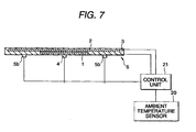
- an ambient temperature sensor is attached to a location separated from the heater to such an extent that it is not influenced by the heater temperature, and a control mechanism is provided to control, on the basis of a temperature detected by the ambient temperature sensor, temperatures of the first and second heating conductor patterns so that temperatures of the first and second heating conductor patterns are kept at given values independent of ambient temperature.
- a current fed to the heating conductor pattern is controlled in accordance with an ambient temperature detected by the ambient temperature sensor so that heating temperatures of the first and second heating conductor patterns are invariable irrespective of a variation of the ambient temperature. Accordingly, the heating of the protective member is made uniform independent of the ambient temperature.
- the above-mentioned heating apparatus comprises a heating chamber, clamping member and a cover.
- the heating chamber With the heating chamber, the heater can be secured.
- the cover With the cover attached to the heating chamber, it is possible to close the heating chamber to thereby confine the heat within the heating chamber.
- the above-mentioned object can be achieved by a method of heating a protective member for protecting a fusion splicing part of optical fibers, the heating method comprising the steps of:
- Figs. 1 and 2 show four types of heaters which are used for a heating apparatus according to the present invention.
- Figs. 1A and 2A are plan views showing the heaters
- Figs. 1B, 2B, 2C and 2D are longitudinal views showing the same.
- reference numeral 1 designates a first heating conductor pattern; 2, 2a and 2b, second heating conductor patterns; 3, 3a and 3b a plate-shaped member; 4, a first temperature sensor; 5a and 5b, second temperature sensors; and 6 and 6', heaters.
- Broken lines indicate arrangements of the first heating conductor pattern 1 or the second heating conductor patterns 2, 2a and 2b as shown in Figs. 1A and 2A.
- the heater 6 shown in Figs. 1A and 1B is composed of the heating conductor patterns 1 and 2 and the elongated plate-shaped member 3.
- the heating conductor patterns 1 and 2 are disposed in the plate-shaped member 3, and current may be fed to those individual conductor patterns by way of lead wires (not shown) led out of those conductor patterns.
- the plate-shaped member 3 is made of heat-resistive and good insulated material, such as ceramic, and is about 70 mm long, about 10 mm wide and about 1 mm thick.
- the first heating conductor pattern 1 is disposed in the central portion of the plate-shaped member 3, and the second heating conductor pattern 2 is disposed in the substantially entire area of the plate-shaped member 3 including both end portions as shown in Figs. 1A and 1B.
- the second heating conductor pattern 2 may be disposed in the entire area of the plate-shaped member 3 while extending both ends of the plate-shaped member 3.
- the first temperature sensor 4 e.g., a thermistor
- the second temperature sensors 5a and 5b e.g., thermistors, are secured to two locations within the areas of the plate-shaped member 3 within which the second heating conductor pattern 2 is disposed, so as to detect a temperature of the second heating conductor pattern 2.
- the heater 6' shown in Fig. 2A and 2B is composed of the first heating conductor pattern 1, the second heating conductor patterns 2a and 2b and the plate-shaped member 3.
- the first heating conductor pattern 1, and the second heating conductor patterns 2a and 2b are disposed in the plate-shaped member 3 similar to those of the heater 6, and current may be fed to those individual conductor patterns by way of lead wires (not shown) let out of those conductor patterns.
- the first heating conductor pattern 1 is disposed in the central portion of the plate-shaped member 3.
- the second heating conductor patterns 2a and 2b are respectively disposed in the areas of the plate-shaped member which are symmetrical with respect to the central portion thereof while including both end portions.
- the second heating conductor patterns 2a and 2b and the first heating conductor pattern 1 are disposed in an overlapping fashion as shown Fig. 2B. If required, those first and second conductor patterns may be disposed while somewhat separated from each other as shown in Fig. 2C. Such separately disposed them are connected electrically and fed with current through a set of lead wires (not shown) in a series fashion. Further, the second heating conductor patterns 2a and 2b may extend to both ends of the plate-shaped member 3 individually.
- the first temperature sensor 4 is secured to one location within the area of the plate-shaped member 3 within which the first heating conductor pattern 1 is disposed, so as to detect the temperature of the first heating conductor pattern 1.
- the second temperature sensors 5a and 5b are secured to two locations within the areas of the plate-shaped member 3 within which the second heating conductor patterns 2a and 2b are disposed, so as to detect temperatures of the second heating conductor patterns 2a and 2b.
- the second temperature sensors 5a and 5b are secured symmetrically with respect to the center. If required, one temperature sensor may be used instead of two temperature sensors.
- the second temperature sensors 5a and 5b are disposed apart from the first heating conductor pattern, to thereby lessen the influence of temperature of the first heating conductor pattern.
- the positions of the second temperature sensors 5a and 5b are not center of the second heating conductor pattern 2. However, it is possible to predict a maximum temperature of the second heating conductor pattern 2 on the basis of a temperature at the corresponding sensor position.
- the first heating conductor pattern 1 is disposed in the lower part of the plate-shaped member, while the second heating conductor pattern 2 is disposed in the upper part. Even if the first heating conductor pattern 1 is disposed in the upper part and the second heating conductor pattern 2 is disposed in the lower part, the function of the heater containing them is little changed since thickness of the plate-shaped member 3 is about 1 mm. Similarly, in Fig. 2, if required, the first heating conductor pattern 1 may be disposed in the lower part, and the second heating conductor patterns 2a and 2b may be disposed in the lower part.
- a resistance value of the first heating conductor pattern 1 is selected to be equal to that of the second heating conductor pattern 2 or the second heating conductor patterns 2, 2a and 2b, and that those patterns are selectively fed with electric power from the power supply to the fusion splicing apparatus to heat.
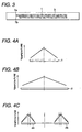
- Fig. 3 is a diagram showing a circuit pattern of the first heating conductor pattern 1.
- the first heating conductor pattern 1 consists of a circuit pattern configured like a combination of letters U as shown in Fig. 3.
- the circuit is secured in the plate-shaped member 3 made of ceramic, for example. Lead wires 7a and 7b are led out of the circuit, for feeding current.
- the circuit pattern is not limited to that of the Fig. 3, but may take any pattern if it is able to provide a predetermined resistance required for the conductor circuit.
- Such a circuit pattern may be formed in a manner that one of the surfaces of a thin ceramic plate is coated with conductive coating, a circuit pattern is printed thereon to form a conductor circuit, lead wires are connected thereto, and finally another ceramic plate is laminated thereon while covering the conductor circuit.
- the first and second heating conductor patterns are buried in one plate-shaped member. If required, the first heating conductor pattern may be buried into a plate-shaped member, and the second heating conductor pattern or patterns may be buried in another plate-shaped member. In this case, the first heating conductor pattern is printed on a top surface of one plate-shaped member, and the second heating conductor pattern or patterns are printed on a top surface of another plate-shaped member.
- Those plate-shaped members 3a, 3b printed the conductor patterns 1, 2a, 2b are arranged in parallel in a state that the printing surface of those members are confronted with each other while a spacer 7 is disposed therebetween as shown in Fig.
- two plate-shaped members 3a, 3b containing the first and second heating conductor patterns 1, 2 may be combined to form a heater 6' as shown in fig. 2E.
- Figs. 4A-4C shows graphs of heating temperature distributions of the heaters shown in Figs. 1A and 1B and 2A and 2B.
- the heater shown in Figs. 1A and 1B includes a temperature distribution as shown in Fig. 4A for the first heating conductor pattern 1, and another temperature distribution as shown in Fig. 4B for the second heating conductor pattern 2.
- the heater shown in Fig. 2A, 2B includes the temperature distribution shown in Fig. 4A for the first heating conductor pattern 1, and temperature distributions as shown in Fig. 4C for the separate second heating conductor patterns 2a and 2b.
- the temperature distribution curves of Figs. 4A and 4B are each configured to have an inverse V shape whose center corresponds to the center of the each heating conductor pattern.
- the temperature distribution curves of Fig. 4C for the separate second heating conductor patterns are each configured to have an inverse V shape as indicated by a solid line. If required, the temperature distribution curves may be configured such that the top of the each inverse V shape is shifted toward the center as indicated by broken line. In the case of the circuit pattern such as shown in Fig. 3, such temperature distributions may be formed by varying the pitch of a series of letter U in the longitudinal direction.
- Fig. 5 is a graph showing a model of temperature variations of the heating conductor patterns over a time range from the start of heating to the cooling. Temperatures in the graph of Fig. 5 represent temperatures detected at the positions of the first and second temperature sensors. That is, a solid line A in the graph represents a temperature of the first heating conductor pattern detected by the first temperature sensor and a solid line B represents a temperature of the second heating conductor pattern detected by the second temperature sensor.
- an object to be heated is placed on the heater, and current is fed to the first heating conductor pattern.
- a temperature of the first heating conductor pattern rises, and the temperature detected by the first temperature sensor disposed at the central portion reaches a predetermined temperature T1.
- the predetermined temperature T1 is kept for a predetermined time t1 by controlling the current fed thereto.
- the heating of the heater and the heated object disposed thereon gradually progresses from the center to both ends.
- the feeding of current to the first heating conductor pattern is stopped, while at the same time feeding of current to the second heating conductor pattern is started.
- the preset temperature T2 is kept for a preset time t2 by controlling the current fed thereto.
- a temperature of the first heating conductor pattern decreases, while a temperature of the second heating conductor pattern rises.
- the object to be heated is heated by the remaining heat of the first heating conductor pattern and the heat from the second heating conductor pattern.
- the object to be heated is heated by the heat from the second heating conductor pattern, and the heating further progresses toward both ends thereof.
- the object may be gradually heated from the center towards both the ends by properly selecting the temperatures T1, T2 and times t1, t2 according to the size of the object.
- T1 190°C
- T2 160°C
- t1 30 seconds
- t2 10 seconds.
- the whole heating time is remarkably reduced; the conventional heating time of 100 to 150 seconds is reduced to 70 to 120 seconds, that is, the whole heating time is reduced by about 20%.
- Fig. 6 is a perspective view showing a heating apparatus with a heater assembled thereinto.
- Reference numeral 6 is a heater; 8, a heating chamber; 8a, a cover; 9, a clamping member; 9a, a holding plate; and 9b, a fiber receiving groove.
- a protective member, an object to be heated, covering an optical fiber fusion splicing part is placed on the heater 6 secured in the heating chamber 8.
- Coated optical fibers connecting to both ends of the optical fiber fusion splicing part are put in fiber receiving grooves 9b of clamping members 9 which are disposed next to the ends of the heating chamber, and holding plates 9a are closed to hold them. In this way, the object to be heated is reliably held on along the heater.
- a cover 8a is preferably used to close the heating chamber 8 to confine the heat within the heating chamber.
- the protective member placed on the heater 6 is heated by the heat of the heater 6.
- the protective member as the object to be heated is put on the heater in a state that it is in contact with the heater, in order to improve the heating efficiency. Therefore, the surface of the heater which is in contact with the protective member is preferably coated with fluorine plastic so as to prevent the protective member from sticking to the heater surface.
- an ambient temperature sensor 20 e.g., a thermistor
- a current fed to the heating conductor pattern is controlled, by a control unit 21, in accordance with an ambient temperature detected thereby so that heating temperatures of the heating conductor patterns are invariable irrespective of a variation of the ambient temperature. In this way, the heating of the protective member is made uniform independent of the ambient temperature. Further, if a relationship between ambient temperature and current fed to the heating conductor pattern is measured and recorded in advance, the current fed thereto may be controlled so as to attain a desired heating temperature by use of the recorded relation if an ambient temperature is known.
- the present invention is based on Japanese Patent Application No. Hei. 11-182779, which is incorporated herein by reference.
Landscapes
- Physics & Mathematics (AREA)
- Engineering & Computer Science (AREA)
- Plasma & Fusion (AREA)
- General Physics & Mathematics (AREA)
- Optics & Photonics (AREA)
- Mechanical Coupling Of Light Guides (AREA)
- Control Of Resistance Heating (AREA)
Abstract
Description
Claims (10)
- A heating apparatus for heating a protective member which protects a fusion splicing part of optical fibers, said heating apparatus comprising:a heater including a plate-shaped member which is made of heat-resistive and insulated material and has an elongated shape extending in a longitudinal direction, a first heating conductor pattern disposed in a central portion of said plate-shaped member in the longitudinal direction, and a second heating conductor pattern disposed in both end portions of said plate-shaped member in the longitudinal direction,
wherein said first heating conductor pattern and said second heating conductor pattern are independently controlled their temperatures. - The heating apparatus in accordance with claim 1, wherein said second heating conductor pattern extends from one end portion of said plate-shaped member to the other end portion thereof in the longitudinal direction.
- The heating apparatus in accordance with claim 1, wherein said second heating conductor pattern comprises two heating conductor patterns which are separately disposed in one end portion of said plate-shaped member and the other end portion thereof in the longitudinal direction while being close to both ends of said first heating conductor pattern.
- The heating apparatus in accordance with claim 1, wherein said second heating conductor pattern comprises two heating conductor patterns which are separately disposed in one end portion of said plate-shaped member and the other end portion thereof in the longitudinal direction while overlapping with said first heating conductor pattern.
- The heating apparatus in accordance with claim 3 or 4, wherein said two heating conductor patterns are disposed symmetrical with respect to the center of the plate-shaped member.
- The heating apparatus in accordance with claim 1, further comprising a first temperature sensor for detecting a temperature of said first heating conductor pattern, a second temperature sensor for detecting a temperature of said second heating conductor pattern, and a control mechanism which controls temperatures of said first and second heating conductor patterns separately on the basis of temperatures detected by said first or second temperature sensors respectively.
- The heating apparatus in accordance with claim 6, further comprising an ambient temperature sensor disposed at such a position that said ambient temperature sensor is not affected by a temperature of said heater, wherein said control mechanism controls the temperatures of said first and second heating conductor patterns separately, on the basis of a temperature detected by said ambient temperature sensor in addition to the temperatures detected by said first or second temperature sensors respectively.
- The heating apparatus in accordance with claim 1, further comprising a heating chamber for securing said heater and a champing members disposed next to both ends of said heating chamber separately.
- The heating apparatus in accordance with claim 1, wherein said plate-shaped member comprises a first plate-shaped member in which said first heating conductor pattern is disposed and a second plate-shaped member in which said second heating conductor pattern is disposed.
- A method of heating a protective member for protecting a fusion splicing part of optical fibers, said heating method comprising the steps of:putting a protective member covering with an optical fiber fusion splicing part along a heater, said heater including a plate-shaped member which is made of heat-resistive and insulated material and an elongated shape extending in a longitudinal direction, a first heating conductor pattern disposed in a central portion of said plate-shaped member in the longitudinal direction, and a second heating conductor pattern disposed in both end portions of said plate-shaped member in the longitudinal direction;heating said first heating conductor pattern to attain a predetermined temperature;keeping said predetermined temperature of said first heating conductor pattern for a predetermined time;stopping the heating of said first heating conductor pattern;heating said second heating conductor pattern to be a preset temperature;keeping said preset temperature of said second heating conductor pattern for a preset time;stopping the heating of said second heating conductor pattern to return a temperature of the optical fiber fusion splicing part covered with said protective member to ambient temperature.
Applications Claiming Priority (2)
| Application Number | Priority Date | Filing Date | Title |
|---|---|---|---|
| JP18277999A JP3293594B2 (en) | 1999-06-29 | 1999-06-29 | Apparatus and method for heating protective member of optical fiber fusion spliced part |
| JP18277999 | 1999-06-29 |
Publications (3)
| Publication Number | Publication Date |
|---|---|
| EP1065536A2 true EP1065536A2 (en) | 2001-01-03 |
| EP1065536A3 EP1065536A3 (en) | 2003-09-03 |
| EP1065536B1 EP1065536B1 (en) | 2005-09-07 |
Family
ID=16124281
Family Applications (1)
| Application Number | Title | Priority Date | Filing Date |
|---|---|---|---|
| EP00113673A Expired - Lifetime EP1065536B1 (en) | 1999-06-29 | 2000-06-28 | An apparatus and a method for heating a protective member for an optical fiber fusion splicing part |
Country Status (10)
| Country | Link |
|---|---|
| US (2) | US6437299B1 (en) |
| EP (1) | EP1065536B1 (en) |
| JP (1) | JP3293594B2 (en) |
| KR (1) | KR100372191B1 (en) |
| CN (1) | CN1163772C (en) |
| AU (1) | AU738558B2 (en) |
| CA (1) | CA2312367A1 (en) |
| DE (1) | DE60022438T2 (en) |
| SG (1) | SG97153A1 (en) |
| TW (1) | TW448321B (en) |
Cited By (1)
| Publication number | Priority date | Publication date | Assignee | Title |
|---|---|---|---|---|
| EP1293812A1 (en) * | 2001-09-13 | 2003-03-19 | Sumitomo Electric Industries, Ltd. | Apparatus and method for heating optical fiber using electric discharge |
Families Citing this family (35)
| Publication number | Priority date | Publication date | Assignee | Title |
|---|---|---|---|---|
| JP3293594B2 (en) * | 1999-06-29 | 2002-06-17 | 住友電気工業株式会社 | Apparatus and method for heating protective member of optical fiber fusion spliced part |
| US6657169B2 (en) * | 1999-07-30 | 2003-12-02 | Stratagene | Apparatus for thermally cycling samples of biological material with substantial temperature uniformity |
| US7003985B2 (en) * | 2001-10-01 | 2006-02-28 | Swain Robert F | Method and apparatus for removing polymeric coatings from optical fiber in a non-oxidizing environment |
| DE10252019A1 (en) * | 2002-11-06 | 2004-05-27 | Convenience Food Systems Wallau Gmbh & Co Kg | Electrical heater for packing machine, includes electrically-conducting bridge in a material, geometry and arrangement promoting desired temperature distribution |
| US7193180B2 (en) * | 2003-05-21 | 2007-03-20 | Lexmark International, Inc. | Resistive heater comprising first and second resistive traces, a fuser subassembly including such a resistive heater and a universal heating apparatus including first and second resistive traces |
| US7212718B2 (en) * | 2003-11-12 | 2007-05-01 | Sumitomo Electric Industries, Ltd. | Apparatus and method for heat-treatment of optical fiber reinforcing member and optical fiber fusion splicing apparatus |
| RU2334258C1 (en) * | 2005-06-09 | 2008-09-20 | Сумитомо Электрик Индастриз, Лтд. | Heater of joint protection, reflow fusion unit including heater of joint protection, and method of reflow fusion |
| JP2007310080A (en) * | 2006-05-17 | 2007-11-29 | Sumitomo Electric Ind Ltd | Optical fiber reinforcement processing apparatus and reinforcement processing method |
| JP4981521B2 (en) * | 2006-06-28 | 2012-07-25 | 中部電力株式会社 | Reinforcing sleeve structure and method for reinforcing fusion splice |
| US9161393B2 (en) * | 2006-10-04 | 2015-10-13 | T+Ink, Inc. | Heated textiles and methods of making the same |
| US8008606B2 (en) * | 2006-10-04 | 2011-08-30 | T-Ink, Inc. | Composite heating element with an integrated switch |
| US20080083720A1 (en) * | 2006-10-04 | 2008-04-10 | T-Ink, Inc. | Method of heating an article |
| US7934874B2 (en) | 2006-11-13 | 2011-05-03 | Sumitomo Electric Industries, Ltd. | Holder, fusion-splicing apparatus, and manufacturing method of optical connector |
| US8550728B2 (en) * | 2007-02-13 | 2013-10-08 | Fujikura Ltd. | Method connecting optical fiber of optical connector with optical transmission element, connector-attached optical transmission element, optical connector, and assembling method of optical connector |
| CA2636096A1 (en) * | 2007-08-02 | 2009-02-02 | Shawcor Ltd. | System for splicing fiber optic drop cables |
| US20090039075A1 (en) * | 2007-08-07 | 2009-02-12 | Michilin Prosperity Co., Ltd | Heat element for maintaining laminator at predetermined working temperature |
| WO2009031426A1 (en) * | 2007-09-07 | 2009-03-12 | Sumitomo Electric Industries, Ltd. | Protection sleeve, and apparatus and method for producing protection sleeve |
| US8193473B2 (en) * | 2008-02-08 | 2012-06-05 | Ngk Insulators, Ltd. | Uniform temperature heater |
| JP4719755B2 (en) * | 2008-02-29 | 2011-07-06 | 住友電気工業株式会社 | Optical connector |
| DE602008001156D1 (en) * | 2008-03-28 | 2010-06-17 | Braun Gmbh | Heating element with temperature sensor |
| TWI436113B (en) | 2008-08-26 | 2014-05-01 | Fujikura Ltd | Fiber fuse terminator, fiber laser, and optical transmission line |
| JP5224385B2 (en) * | 2009-04-10 | 2013-07-03 | 古河電気工業株式会社 | Heat treatment apparatus and heat treatment method for optical fiber reinforcing member |
| US8822887B2 (en) * | 2010-10-27 | 2014-09-02 | Shaw Arrow Development, LLC | Multi-mode heater for a diesel emission fluid tank |
| JP5857889B2 (en) * | 2012-06-26 | 2016-02-10 | 住友電気工業株式会社 | Protective sleeve |
| CN104520741B (en) * | 2012-08-03 | 2017-12-26 | Sei光学前沿株式会社 | Heat treatment apparatus for optical fiber reinforcing member, the optical fibre fusion splicer for being provided with the heat treatment apparatus and heat-treating methods are carried out to optical fiber reinforcing member |
| CN104718477B (en) | 2013-03-25 | 2018-10-26 | 株式会社藤仓 | Optical fiber interconnecting piece strengthens heating device |
| US10663666B2 (en) * | 2013-12-05 | 2020-05-26 | United States Of America As Represented By The Secretary Of The Navy | Flexible, low profile kink resistant fiber optic splice tension sleeve |
| JP6318435B2 (en) * | 2014-01-28 | 2018-05-09 | Seiオプティフロンティア株式会社 | Reinforcing device for optical fiber connection |
| JP6249521B2 (en) * | 2014-01-28 | 2017-12-20 | Seiオプティフロンティア株式会社 | Optical fiber fusion splicer |
| JP6320766B2 (en) | 2014-01-28 | 2018-05-09 | Seiオプティフロンティア株式会社 | Optical fiber fusion splicer |
| JP6628247B2 (en) * | 2016-05-19 | 2020-01-08 | Seiオプティフロンティア株式会社 | Device for reinforcing optical fiber fusion splice and fusion splicer equipped therewith |
| JP6758143B2 (en) * | 2016-09-29 | 2020-09-23 | 日本特殊陶業株式会社 | Heating device |
| JP6767833B2 (en) * | 2016-09-29 | 2020-10-14 | 日本特殊陶業株式会社 | Heating device |
| CN107942439B (en) * | 2017-12-25 | 2024-04-02 | 南京吉隆光纤通信股份有限公司 | Unit template for forming V-shaped groove for heating heat shrinkage tube of optical fiber fusion splicer |
| JP7585057B2 (en) * | 2021-01-19 | 2024-11-18 | 古河電気工業株式会社 | Reinforcement sleeve and reinforcement structure for optical fiber connection |
Family Cites Families (20)
| Publication number | Priority date | Publication date | Assignee | Title |
|---|---|---|---|---|
| CH122021A (en) * | 1926-09-30 | 1927-08-16 | Schmid Vetter Emil | Electric hotplate. |
| US2878357A (en) * | 1956-07-13 | 1959-03-17 | Gen Dynamics Corp | Electric heated laminated glass panel |
| US3475588A (en) * | 1968-08-20 | 1969-10-28 | Permaglass | Defrosting and deicing window assembly |
| CA1197963A (en) * | 1981-07-22 | 1985-12-17 | Michito Matsumoto | Apparatus and method for heating heat-shrinkable tubes |
| DE3265723D1 (en) * | 1982-03-18 | 1985-10-03 | Turgut Koruk | Quantized (digital) heating plate |
| JPS58212915A (en) * | 1982-06-04 | 1983-12-10 | Sumitomo Electric Ind Ltd | Method and apparatus for heating thermally shrinkable tube |
| JPS6198302A (en) * | 1984-10-19 | 1986-05-16 | Fujikura Ltd | Heating device of thermal contraction tube |
| DE3513157A1 (en) * | 1985-04-12 | 1986-10-16 | VEGLA Vereinigte Glaswerke GmbH, 5100 Aachen | Method for regulating the temperature of window panes which can be heated electrically |
| JPH03295185A (en) * | 1990-04-13 | 1991-12-26 | Matsushita Electric Ind Co Ltd | Heating element |
| JPH0420721A (en) * | 1990-05-15 | 1992-01-24 | Toshiba Corp | Heat cooking apparatus |
| JPH04271307A (en) * | 1991-02-27 | 1992-09-28 | Sumitomo Electric Ind Ltd | Reinforcing member for optical coupler and method for reinforcing optical coupler |
| DE4130337C2 (en) * | 1991-09-12 | 2002-05-02 | Ego Elektro Blanc & Fischer | Method for operating an electric heating unit and electric heating unit |
| JPH05326112A (en) * | 1992-05-21 | 1993-12-10 | Shin Etsu Chem Co Ltd | Layered ceramic heater |
| JP3295185B2 (en) | 1993-09-09 | 2002-06-24 | 光洋精工株式会社 | Bearing abnormality detection device |
| JP3477062B2 (en) * | 1997-12-26 | 2003-12-10 | 京セラ株式会社 | Wafer heating device |
| JP3293594B2 (en) * | 1999-06-29 | 2002-06-17 | 住友電気工業株式会社 | Apparatus and method for heating protective member of optical fiber fusion spliced part |
| JP2001102157A (en) * | 1999-10-01 | 2001-04-13 | Ngk Insulators Ltd | Ceramic heater |
| ATE301916T1 (en) * | 1999-11-19 | 2005-08-15 | Ibiden Co Ltd | CERAMIC HEATER |
| JP3222119B2 (en) * | 1999-11-19 | 2001-10-22 | イビデン株式会社 | Ceramic heater for semiconductor manufacturing and inspection equipment |
| JP4028149B2 (en) * | 2000-02-03 | 2007-12-26 | 日本碍子株式会社 | Heating device |
-
1999
- 1999-06-29 JP JP18277999A patent/JP3293594B2/en not_active Expired - Lifetime
-
2000
- 2000-06-23 SG SG200003539A patent/SG97153A1/en unknown
- 2000-06-23 TW TW089112431A patent/TW448321B/en not_active IP Right Cessation
- 2000-06-26 AU AU42676/00A patent/AU738558B2/en not_active Ceased
- 2000-06-27 US US09/605,419 patent/US6437299B1/en not_active Expired - Lifetime
- 2000-06-27 KR KR10-2000-0035581A patent/KR100372191B1/en not_active Expired - Fee Related
- 2000-06-27 CA CA002312367A patent/CA2312367A1/en not_active Abandoned
- 2000-06-28 EP EP00113673A patent/EP1065536B1/en not_active Expired - Lifetime
- 2000-06-28 DE DE60022438T patent/DE60022438T2/en not_active Expired - Lifetime
- 2000-06-29 CN CNB001187929A patent/CN1163772C/en not_active Expired - Lifetime
-
2002
- 2002-03-19 US US10/099,990 patent/US6518551B2/en not_active Expired - Lifetime
Cited By (1)
| Publication number | Priority date | Publication date | Assignee | Title |
|---|---|---|---|---|
| EP1293812A1 (en) * | 2001-09-13 | 2003-03-19 | Sumitomo Electric Industries, Ltd. | Apparatus and method for heating optical fiber using electric discharge |
Also Published As
| Publication number | Publication date |
|---|---|
| DE60022438D1 (en) | 2005-10-13 |
| SG97153A1 (en) | 2003-07-18 |
| CA2312367A1 (en) | 2000-12-29 |
| KR20010069212A (en) | 2001-07-23 |
| US6437299B1 (en) | 2002-08-20 |
| AU4267600A (en) | 2001-01-04 |
| EP1065536B1 (en) | 2005-09-07 |
| JP2001013355A (en) | 2001-01-19 |
| US6518551B2 (en) | 2003-02-11 |
| EP1065536A3 (en) | 2003-09-03 |
| CN1287278A (en) | 2001-03-14 |
| TW448321B (en) | 2001-08-01 |
| KR100372191B1 (en) | 2003-02-17 |
| CN1163772C (en) | 2004-08-25 |
| US20020148827A1 (en) | 2002-10-17 |
| JP3293594B2 (en) | 2002-06-17 |
| DE60022438T2 (en) | 2006-01-19 |
| AU738558B2 (en) | 2001-09-20 |
Similar Documents
| Publication | Publication Date | Title |
|---|---|---|
| US6437299B1 (en) | Heating apparatus for splice protector with separate heating conductor patterns | |
| US7212718B2 (en) | Apparatus and method for heat-treatment of optical fiber reinforcing member and optical fiber fusion splicing apparatus | |
| CN101606091B (en) | Protection sleeve, and apparatus and method for producing protection sleeve | |
| US4526732A (en) | Method of heating thermal shrinkage tube and apparatus therefor | |
| WO2007132898A1 (en) | Optical fiber reinforcing device and reinforcing method | |
| EP1022596B1 (en) | Heat-shrinkable tube for protection of optical fiber splices | |
| KR101915592B1 (en) | Efficient heating groove for optical-fiber fusion splicer and optical-fiber fusion splicer | |
| JP2005257855A (en) | Heat treatment apparatus and heat treatment method for optical fiber reinforcing member, and optical fiber fusion splicing apparatus | |
| US10048442B2 (en) | Reinforcement device for optical-fiber spliced section | |
| JP2003075678A (en) | Fusion splicing method and fusion splicing apparatus for multi-core optical fiber | |
| JP4165375B2 (en) | Heat treatment apparatus and heat treatment method for optical fiber reinforcing member, and optical fiber fusion splicing apparatus | |
| JP5224385B2 (en) | Heat treatment apparatus and heat treatment method for optical fiber reinforcing member | |
| JP2003021744A (en) | Fusion splicing method and fusion splicing device for multi-core optical fiber | |
| JP2561264Y2 (en) | Optical fiber stripper | |
| JPH10319270A (en) | Heat shrink sleeve heating device for reinforcing optical fiber connection | |
| JP2020070527A (en) | Carbon fiber bonding equipment | |
| JPS6146909A (en) | Reinforcing heater of optical fiber welded and connected part | |
| JPH06347663A (en) | Reinforcement of optical fiber connection with heat shrink tube |
Legal Events
| Date | Code | Title | Description |
|---|---|---|---|
| PUAI | Public reference made under article 153(3) epc to a published international application that has entered the european phase |
Free format text: ORIGINAL CODE: 0009012 |
|
| AK | Designated contracting states |
Kind code of ref document: A2 Designated state(s): AT BE CH CY DE DK ES FI FR GB GR IE IT LI LU MC NL PT SE |
|
| AX | Request for extension of the european patent |
Free format text: AL;LT;LV;MK;RO;SI |
|
| PUAL | Search report despatched |
Free format text: ORIGINAL CODE: 0009013 |
|
| AK | Designated contracting states |
Kind code of ref document: A3 Designated state(s): AT BE CH CY DE DK ES FI FR GB GR IE IT LI LU MC NL PT SE |
|
| AX | Request for extension of the european patent |
Extension state: AL LT LV MK RO SI |
|
| RIC1 | Information provided on ipc code assigned before grant |
Ipc: 7G 02B 6/38 B Ipc: 7G 02B 6/255 A |
|
| 17P | Request for examination filed |
Effective date: 20031205 |
|
| 17Q | First examination report despatched |
Effective date: 20040116 |
|
| AKX | Designation fees paid |
Designated state(s): DE FR GB IT SE |
|
| GRAP | Despatch of communication of intention to grant a patent |
Free format text: ORIGINAL CODE: EPIDOSNIGR1 |
|
| GRAS | Grant fee paid |
Free format text: ORIGINAL CODE: EPIDOSNIGR3 |
|
| GRAA | (expected) grant |
Free format text: ORIGINAL CODE: 0009210 |
|
| AK | Designated contracting states |
Kind code of ref document: B1 Designated state(s): DE FR GB IT SE |
|
| REG | Reference to a national code |
Ref country code: GB Ref legal event code: FG4D |
|
| REF | Corresponds to: |
Ref document number: 60022438 Country of ref document: DE Date of ref document: 20051013 Kind code of ref document: P |
|
| REG | Reference to a national code |
Ref country code: SE Ref legal event code: TRGR |
|
| ET | Fr: translation filed | ||
| PLBE | No opposition filed within time limit |
Free format text: ORIGINAL CODE: 0009261 |
|
| STAA | Information on the status of an ep patent application or granted ep patent |
Free format text: STATUS: NO OPPOSITION FILED WITHIN TIME LIMIT |
|
| 26N | No opposition filed |
Effective date: 20060608 |
|
| REG | Reference to a national code |
Ref country code: FR Ref legal event code: PLFP Year of fee payment: 17 |
|
| REG | Reference to a national code |
Ref country code: FR Ref legal event code: PLFP Year of fee payment: 18 |
|
| REG | Reference to a national code |
Ref country code: FR Ref legal event code: PLFP Year of fee payment: 19 |
|
| PGFP | Annual fee paid to national office [announced via postgrant information from national office to epo] |
Ref country code: DE Payment date: 20190618 Year of fee payment: 20 Ref country code: IT Payment date: 20190620 Year of fee payment: 20 |
|
| PGFP | Annual fee paid to national office [announced via postgrant information from national office to epo] |
Ref country code: FR Payment date: 20190510 Year of fee payment: 20 Ref country code: SE Payment date: 20190611 Year of fee payment: 20 |
|
| PGFP | Annual fee paid to national office [announced via postgrant information from national office to epo] |
Ref country code: GB Payment date: 20190626 Year of fee payment: 20 |
|
| REG | Reference to a national code |
Ref country code: DE Ref legal event code: R071 Ref document number: 60022438 Country of ref document: DE |
|
| REG | Reference to a national code |
Ref country code: GB Ref legal event code: PE20 Expiry date: 20200627 |
|
| REG | Reference to a national code |
Ref country code: SE Ref legal event code: EUG |
|
| PG25 | Lapsed in a contracting state [announced via postgrant information from national office to epo] |
Ref country code: GB Free format text: LAPSE BECAUSE OF EXPIRATION OF PROTECTION Effective date: 20200627 |