EP1065490A2 - Methods and apparatus for suppressing engine test cell howl - Google Patents
Methods and apparatus for suppressing engine test cell howl Download PDFInfo
- Publication number
- EP1065490A2 EP1065490A2 EP00303620A EP00303620A EP1065490A2 EP 1065490 A2 EP1065490 A2 EP 1065490A2 EP 00303620 A EP00303620 A EP 00303620A EP 00303620 A EP00303620 A EP 00303620A EP 1065490 A2 EP1065490 A2 EP 1065490A2
- Authority
- EP
- European Patent Office
- Prior art keywords
- distorter
- flow
- support
- accordance
- engine
- Prior art date
- Legal status (The legal status is an assumption and is not a legal conclusion. Google has not performed a legal analysis and makes no representation as to the accuracy of the status listed.)
- Granted
Links
- 238000012360 testing method Methods 0.000 title claims abstract description 26
- 238000000034 method Methods 0.000 title claims abstract 6
- 230000035515 penetration Effects 0.000 claims description 8
- XLYOFNOQVPJJNP-UHFFFAOYSA-N water Substances O XLYOFNOQVPJJNP-UHFFFAOYSA-N 0.000 claims description 4
- 239000000498 cooling water Substances 0.000 claims description 3
- 229910000975 Carbon steel Inorganic materials 0.000 claims description 2
- 239000010962 carbon steel Substances 0.000 claims description 2
- 239000010935 stainless steel Substances 0.000 claims description 2
- 229910001220 stainless steel Inorganic materials 0.000 claims description 2
- 230000035939 shock Effects 0.000 description 3
- 239000000463 material Substances 0.000 description 2
- 238000005259 measurement Methods 0.000 description 2
- 230000003116 impacting effect Effects 0.000 description 1
- 230000000149 penetrating effect Effects 0.000 description 1
- 238000011144 upstream manufacturing Methods 0.000 description 1
Images


Classifications
-
- B—PERFORMING OPERATIONS; TRANSPORTING
- B64—AIRCRAFT; AVIATION; COSMONAUTICS
- B64F—GROUND OR AIRCRAFT-CARRIER-DECK INSTALLATIONS SPECIALLY ADAPTED FOR USE IN CONNECTION WITH AIRCRAFT; DESIGNING, MANUFACTURING, ASSEMBLING, CLEANING, MAINTAINING OR REPAIRING AIRCRAFT, NOT OTHERWISE PROVIDED FOR; HANDLING, TRANSPORTING, TESTING OR INSPECTING AIRCRAFT COMPONENTS, NOT OTHERWISE PROVIDED FOR
- B64F1/00—Ground or aircraft-carrier-deck installations
- B64F1/26—Ground or aircraft-carrier-deck installations for reducing engine or jet noise; Protecting airports from jet erosion
-
- B—PERFORMING OPERATIONS; TRANSPORTING
- B64—AIRCRAFT; AVIATION; COSMONAUTICS
- B64F—GROUND OR AIRCRAFT-CARRIER-DECK INSTALLATIONS SPECIALLY ADAPTED FOR USE IN CONNECTION WITH AIRCRAFT; DESIGNING, MANUFACTURING, ASSEMBLING, CLEANING, MAINTAINING OR REPAIRING AIRCRAFT, NOT OTHERWISE PROVIDED FOR; HANDLING, TRANSPORTING, TESTING OR INSPECTING AIRCRAFT COMPONENTS, NOT OTHERWISE PROVIDED FOR
- B64F5/00—Designing, manufacturing, assembling, cleaning, maintaining or repairing aircraft, not otherwise provided for; Handling, transporting, testing or inspecting aircraft components, not otherwise provided for
- B64F5/60—Testing or inspecting aircraft components or systems
-
- F—MECHANICAL ENGINEERING; LIGHTING; HEATING; WEAPONS; BLASTING
- F02—COMBUSTION ENGINES; HOT-GAS OR COMBUSTION-PRODUCT ENGINE PLANTS
- F02C—GAS-TURBINE PLANTS; AIR INTAKES FOR JET-PROPULSION PLANTS; CONTROLLING FUEL SUPPLY IN AIR-BREATHING JET-PROPULSION PLANTS
- F02C7/00—Features, components parts, details or accessories, not provided for in, or of interest apart form groups F02C1/00 - F02C6/00; Air intakes for jet-propulsion plants
Definitions
- This invention relates generally to turbine engines, and more specifically, to reducing, if not eliminating, an intense acoustic tone emitted during certain test operating conditions of such engines.
- test cell For testing, turbine engines typically are enclosed within a test cell.
- the test cell is sufficiently large so that the engine is completed enclosed within the cell, and test operators can move about the cell to set test parameters and check engine performance.
- test operators can move about the cell to set test parameters and check engine performance.
- an intense acoustic tone is emitted. This tone sometimes is referred to as "cell howl”.
- the present invention in one aspect, relates to a flow distorter apparatus which suppresses cell howl with negligible impact on engine test conditions.
- the apparatus in an exemplary embodiment, includes a flow distorter configured to be positioned close to a nozzle exit of an engine nozzle, and a flow distorter support for maintaining the flow distorter at a selected location.
- the flow distorter is adjustably secured to the support so that a distance at which a tip of the distorter is located relative to support is adjustable.
- the support includes a base having an adjustable track to enable axial adjustment of the flow distorter relative to a nozzle exit plane.
- the support further includes a first support arm extending vertically from the base, and a second support arm extending angularly from the base to the first support arm.
- the first and second support arms are movable relative to the adjustable track and are secured thereto, for example, by bolts.
- the flow distorter is secured to the first arm by a bolt, and the distorter can be adjusted relative to the first support arm so that the extent to which the distorter tip extends into the engine exhaust flow can be adjusted.
- the distorter axial position PAP and the distorter penetration P into the engine exhaust flow is selected.
- the distorter should be positioned so that it has minimal, or no, impact on engine performance but suppresses, if not totally eliminates, cell howl.
- the above described flow distorter apparatus is effective in reducing cell howl and is quick, easy, and inexpensive to fabricate and install in existing as well as newly fabricated test facilities.
- the flow distorter apparatus is external to the engine nozzle, which minimizes its impact on test measurements. By eliminating cell howl and minimizing test measurement impact, engine tests can be performed reliably and under consistent conditions, and cell howl damage is avoided.
- FIG. 1 is a schematic illustration of broadband supersonic jet noise
- Figure 2 is a schematic illustration of a supersonic jet screech mode.
- air flows in a direction 10 from an exit 12 of an engine nozzle 14.
- Random turbulence 16 generates noise, as shown in Figure 1.
- shock screech occurs when turbulence convects through a quasi-periodic shock cell system in an exhaust plume 18.
- Acoustic waves travel upstream to nozzle exit 12 and then generate new turbulence of the same wavelength as the acoustic waves.
- a resonant feedback loop 20 is established which can produce extremely discrete and intense acoustic tones 22.
- These acoustic tone 22 generate cell howl.
- FIG 3 is a schematic illustration of a flow distorter apparatus 100 located in an operative position relative an engine exhaust nozzle N and a test cell exhaust collector C.
- Apparatus 100 includes a flow distorter 102 positioned close to a nozzle exit E of nozzle N, and a flow distorter support 104 for maintaining flow distorter 102 at a selected location.
- Flow distorter 102 has a square cross sectional shape. Distorter 102 can, however, have many other geometric shapes, and distorter 102 does not necessarily even have to be symmetric about an axis.
- distorter 102 includes a water passage for enabling cooling water to flow through distorter 102.
- Distorter 102 is adjustably secured to support 104 so that a distance at which a tip 106 of distorter 102 is located is adjustable. More specifically, support 104 includes a base 108 which is secured to an adjustable track 110 to enable axial adjustment of flow distorter 112 relative to a nozzle exit plane. Base 108 is secured to track 110 by, for example, bolts. Support 104 further includes a first support arm 112 extending vertically from base 108, and a second support arm114 extending angularly from base 108 to first support arm 112.
- flow distorter 102 is secured to first arm 112 by a bolt, and distorter 102 can be adjusted relative to arm 112 so that the extent to which tip 106 extends into engine exhaust flow moving in a direction indicated by arrow 116 can be adjusted.
- Flow distorter 102 is fabricated from stainless steel.
- Support 104 is fabricated from carbon steel.
- many different types of material can be used, and the present invention is not limited to use in connection with any one particular material.
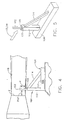
- distorter axial position PAP refers to the distance from nozzle exit E to distorter 102.
- Distorter penetration P refers to the length of the section of distorter 102 located within, or penetrating into, engine exhaust flow 118.
- Distorter 102 should be positioned so that distorter 102 has no impact on engine performance but suppresses, if not totally eliminates, cell howl. In one particular test, it was empirically determined that a penetration P of 4.0 inches and position PAP of 6.9 inches provided acceptable results. Again, the engine characteristics and the distorter characteristics all may have an impact on the specific position of the distorter relative to the engine nozzle exit.
- FIG. 5 is a perspective view of distorter apparatus 100.
- flow distorter 102 has a square cross sectional shape and is adjustably secured to support 104. Specifically, distorter 102 extends into an opening 120 in arm 112, and an adjustment screw 122 extends through arm 112 and is tightened against distorter 102 to maintain distorter102 in position.
- the support as well as the flow distorter may have many different shapes and configurations.
- the flow distorter may, for example, be supported from the ceiling rather than the floor of the test cell as shown in the drawings.
- the support performs the function of controlling the extent to which the flow distorter extends into the exhaust flow, and the axial position of the flow distorter relative to the nozzle exit.
- the distorter performs the function of disrupting the exhaust flow sufficiently so that cell howl is suppressed, but not to the extent of impacting engine operation.
- the distorter eliminates the resonant feedback loops in the exhaust plumes, which eliminates the acoustic tones generated by such loops.
- Many different supports and distorters can be configured to perform these functions, and therefore, the present invention is not limited to the specific embodiments described and illustrated herein.
Landscapes
- Engineering & Computer Science (AREA)
- Aviation & Aerospace Engineering (AREA)
- Chemical & Material Sciences (AREA)
- Combustion & Propulsion (AREA)
- Mechanical Engineering (AREA)
- Manufacturing & Machinery (AREA)
- Transportation (AREA)
- General Engineering & Computer Science (AREA)
- Testing Of Engines (AREA)
- Investigating Strength Of Materials By Application Of Mechanical Stress (AREA)
Abstract
Description
- The United States Government has rights in this invention pursuant to Contract No. F33657-97-4-2059 awarded by the Department of the Air Force.
- This invention relates generally to turbine engines, and more specifically, to reducing, if not eliminating, an intense acoustic tone emitted during certain test operating conditions of such engines.
- For testing, turbine engines typically are enclosed within a test cell. The test cell is sufficiently large so that the engine is completed enclosed within the cell, and test operators can move about the cell to set test parameters and check engine performance. Under certain operating conditions, and with the engine located within a test cell, an intense acoustic tone is emitted. This tone sometimes is referred to as "cell howl".
- The intensity of the tone can sometimes damage the test cell and engine. Known attempts to eliminate cell howl, as described in Jones et al., The Acoustic Response Of Altitude Test Facility Exhaust Systems To Axisymmetric And Two-Dimensional Turbine Engine Exhaust Plumes, DGLR/AIAA 92-02-131, May, 1992, include attempting to optimize a location of the cell exhaust collector relative to an engine nozzle exit, injecting water in an engine exhaust plume, locating volume resonators in the cell exhaust collector, and inserting a secondary concentric duct into the exhaust collector. These known attempts have not proven one hundred percent successful in eliminating cell howl for all engine nozzles, and the howl generated by some nozzles is not even always reduced.
- The present invention, in one aspect, relates to a flow distorter apparatus which suppresses cell howl with negligible impact on engine test conditions. The apparatus, in an exemplary embodiment, includes a flow distorter configured to be positioned close to a nozzle exit of an engine nozzle, and a flow distorter support for maintaining the flow distorter at a selected location.
- The flow distorter is adjustably secured to the support so that a distance at which a tip of the distorter is located relative to support is adjustable. More specifically, and in an exemplary embodiment, the support includes a base having an adjustable track to enable axial adjustment of the flow distorter relative to a nozzle exit plane. The support further includes a first support arm extending vertically from the base, and a second support arm extending angularly from the base to the first support arm. The first and second support arms are movable relative to the adjustable track and are secured thereto, for example, by bolts. Similarly, the flow distorter is secured to the first arm by a bolt, and the distorter can be adjusted relative to the first support arm so that the extent to which the distorter tip extends into the engine exhaust flow can be adjusted.
- Prior to testing operation of an engine in a test cell, the distorter axial position PAP and the distorter penetration P into the engine exhaust flow is selected. The distorter should be positioned so that it has minimal, or no, impact on engine performance but suppresses, if not totally eliminates, cell howl.
- The above described flow distorter apparatus is effective in reducing cell howl and is quick, easy, and inexpensive to fabricate and install in existing as well as newly fabricated test facilities. In addition, the flow distorter apparatus is external to the engine nozzle, which minimizes its impact on test measurements. By eliminating cell howl and minimizing test measurement impact, engine tests can be performed reliably and under consistent conditions, and cell howl damage is avoided.
- An embodiment of the invention will now be described, by way of example, with reference to the accompanying drawings, in which:
- Figure 1 is a schematic illustration of broadband supersonic jet noise;
- Figure 2 is a schematic illustration of a supersonic jet in a screech mode;
- Figure 3 is a schematic illustration of a flow distorter apparatus positioned relative to an engine nozzle;
- Figure 4 which is a schematic illustration of the location of the flow distorter apparatus relative to a nozzle exit; and
- Figure 5 is a perspective view of the flow distorter apparatus shown in Figure 3.
-
- Figure 1 is a schematic illustration of broadband supersonic jet noise, and Figure 2 is a schematic illustration of a supersonic jet screech mode. In the broadband noise condition, air flows in a
direction 10 from anexit 12 of anengine nozzle 14.Random turbulence 16 generates noise, as shown in Figure 1. Referring to Figure 2, shock screech occurs when turbulence convects through a quasi-periodic shock cell system in anexhaust plume 18. Acoustic waves travel upstream tonozzle exit 12 and then generate new turbulence of the same wavelength as the acoustic waves. When the acoustic wavelength is close to the same spacing as the shock cells, aresonant feedback loop 20 is established which can produce extremely discrete and intenseacoustic tones 22. Theseacoustic tone 22 generate cell howl. - Figure 3 is a schematic illustration of a
flow distorter apparatus 100 located in an operative position relative an engine exhaust nozzle N and a test cell exhaustcollector C. Apparatus 100, as shown in Figure 3, includes aflow distorter 102 positioned close to a nozzle exit E of nozzle N, and aflow distorter support 104 for maintainingflow distorter 102 at a selected location.Flow distorter 102 has a square cross sectional shape.Distorter 102 can, however, have many other geometric shapes, anddistorter 102 does not necessarily even have to be symmetric about an axis. In addition, and in an alternative embodiment,distorter 102 includes a water passage for enabling cooling water to flow throughdistorter 102. -
Distorter 102 is adjustably secured to support 104 so that a distance at which atip 106 ofdistorter 102 is located is adjustable. More specifically,support 104 includes abase 108 which is secured to anadjustable track 110 to enable axial adjustment offlow distorter 112 relative to a nozzle exit plane.Base 108 is secured to track 110 by, for example, bolts.Support 104 further includes afirst support arm 112 extending vertically frombase 108, and a second support arm114 extending angularly frombase 108 tofirst support arm 112. Similarly,flow distorter 102 is secured tofirst arm 112 by a bolt, anddistorter 102 can be adjusted relative toarm 112 so that the extent to whichtip 106 extends into engine exhaust flow moving in a direction indicated byarrow 116 can be adjusted. -
Flow distorter 102 is fabricated from stainless steel.Support 104 is fabricated from carbon steel. Of course, many different types of material can be used, and the present invention is not limited to use in connection with any one particular material. - Prior to testing operation of an engine in a test cell, and referring now to Figure 4 which is a schematic illustration of the location of
apparatus 100 relative to nozzle exit F, distorter axial position PAP and distorter penetration P into an exhaust flow 118 are selected. Specifically, distorter axial position PAP refers to the distance from nozzle exit E to distorter 102. Distorter penetration P refers to the length of the section ofdistorter 102 located within, or penetrating into, engine exhaust flow 118. - The particular engine being tested, and the particular shape of
distorter 102 impact the desired axial position PAP and penetration P. Distorter 102 should be positioned so thatdistorter 102 has no impact on engine performance but suppresses, if not totally eliminates, cell howl. In one particular test, it was empirically determined that a penetration P of 4.0 inches and position PAP of 6.9 inches provided acceptable results. Again, the engine characteristics and the distorter characteristics all may have an impact on the specific position of the distorter relative to the engine nozzle exit. - Figure 5 is a perspective view of
distorter apparatus 100. As clearly shown in Figure 5,flow distorter 102 has a square cross sectional shape and is adjustably secured to support 104. Specifically,distorter 102 extends into anopening 120 inarm 112, and anadjustment screw 122 extends througharm 112 and is tightened againstdistorter 102 to maintain distorter102 in position. - Many variations of the above described flow distorter apparatus are possible. For example, the support as well as the flow distorter may have many different shapes and configurations. Also, the flow distorter may, for example, be supported from the ceiling rather than the floor of the test cell as shown in the drawings. Generally, the support performs the function of controlling the extent to which the flow distorter extends into the exhaust flow, and the axial position of the flow distorter relative to the nozzle exit. The distorter performs the function of disrupting the exhaust flow sufficiently so that cell howl is suppressed, but not to the extent of impacting engine operation. Specifically, the distorter eliminates the resonant feedback loops in the exhaust plumes, which eliminates the acoustic tones generated by such loops. Many different supports and distorters can be configured to perform these functions, and therefore, the present invention is not limited to the specific embodiments described and illustrated herein.
Claims (14)
- A method for suppressing cell howl in testing a turbine engine, said method comprising the steps of:locating a flow distorter (102) a selected axial distance PAP from a nozzle exit (E) of the engine; andlocating the flow distorter (102) at a selected penetration P into an exhaust flow path (118) of the engine.
- A method in accordance with Claim 1 wherein the selected distance PAP and penetration P provide that the flow distorter (102) eliminates cell howl.
- A method in accordance with Claim 1 wherein the selected distance PAP and penetration P provide that the flow distorter (102) does not significantly impact engine test operations.
- Apparatus (100) for suppressing engine test cell howl, comprising:a flow distorter (102) configured to be positioned at a selected distance from a nozzle exit (E) of a turbine engine; anda flow distorter support (104) for maintaining said flow distorter (102) at a selected location.
- Apparatus (100) in accordance with Claim 4 wherein said flow distorter (102) comprises a water passage for cooling water to flow through said distorter (102).
- Apparatus (100) in accordance with Claim 4 wherein said support (104) comprises a base (108) and a first support arm (112) extending vertically from said base (108), said distorter (102) adjustably secured to said first support arm (112).
- Apparatus (100) in accordance with Claim 6 wherein said support (104) further comprises a second support arm(114) extending angularly from said base (108) to said first support arm (112).
- Apparatus (100) in accordance with Claim 4 wherein said distorter (102) is stainless steel.
- Apparatus (100) in accordance with Claim 4 wherein said base (104) is carbon steel.
- Apparatus (100) in accordance with Claim 4 wherein said distorter (102) has a square cross sectional shape.
- A flow distorter apparatus (100) comprising:a flow distorter (102) configured to be positioned at a selected distance from a nozzle exit (E) of a turbine engine; anda flow distorter support (104) for maintaining said flow distorter (102) at a selected location, said distorter (102) adjustably secured to said support (104).
- Apparatus (100) in accordance with Claim 10 wherein said flow distorter (102) comprises a water passage for cooling water to flow through said distorter (102).
- Apparatus (100) in accordance with Claim 10 wherein said support (104) comprises a base (108), a first support arm (112) extending vertically from said base (108), and a second support arm (114) extending angularly from said base (108) to said first support arm (112).
- Apparatus (100) in accordance with Claim 11 wherein said flow distorter (102) has a square cross sectional shape.
Applications Claiming Priority (2)
| Application Number | Priority Date | Filing Date | Title |
|---|---|---|---|
| US342821 | 1999-06-29 | ||
| US09/342,821 US6092621A (en) | 1999-06-29 | 1999-06-29 | Methods and apparatus for suppressing engine test cell howl |
Publications (3)
| Publication Number | Publication Date |
|---|---|
| EP1065490A2 true EP1065490A2 (en) | 2001-01-03 |
| EP1065490A3 EP1065490A3 (en) | 2004-07-28 |
| EP1065490B1 EP1065490B1 (en) | 2007-03-07 |
Family
ID=23343416
Family Applications (1)
| Application Number | Title | Priority Date | Filing Date |
|---|---|---|---|
| EP00303620A Expired - Lifetime EP1065490B1 (en) | 1999-06-29 | 2000-04-28 | Methods and apparatus for suppressing engine test cell howl |
Country Status (4)
| Country | Link |
|---|---|
| US (1) | US6092621A (en) |
| EP (1) | EP1065490B1 (en) |
| JP (1) | JP4437250B2 (en) |
| DE (1) | DE60033739T2 (en) |
Families Citing this family (9)
| Publication number | Priority date | Publication date | Assignee | Title |
|---|---|---|---|---|
| US7262334B2 (en) * | 2002-11-13 | 2007-08-28 | Regents Of The University Of Minnesota | Catalytic partial oxidation of hydrocarbons |
| DE502004009480D1 (en) * | 2004-03-03 | 2009-06-25 | Rolls Royce Plc | Arrangement for generating sound fields with a specific modal composition |
| US8015819B2 (en) * | 2006-09-29 | 2011-09-13 | The United States Of America As Represented By The Administrator Of The National Aeronautics And Space Administration | Wet active chevron nozzle for controllable jet noise reduction |
| US8220769B2 (en) | 2007-05-31 | 2012-07-17 | Pratt & Whitney Canada Corp. | System for transporting a gas turbine engine |
| US7735363B2 (en) * | 2007-06-20 | 2010-06-15 | Pratt & Whitney Canada Corp. | Aircraft engine pre-dressing unit for testing facility |
| US7717229B2 (en) * | 2008-05-09 | 2010-05-18 | Siemens Energy, Inc. | Gas turbine exhaust sound suppressor and associated methods |
| US8984888B2 (en) | 2011-10-26 | 2015-03-24 | General Electric Company | Fuel injection assembly for use in turbine engines and method of assembling same |
| US8939253B1 (en) | 2012-04-27 | 2015-01-27 | The United States Of America As Represented By The Administrator Of The National Aeronautics And Space Administration | System and method for suppression of unwanted noise in ground test facilities |
| US9488129B1 (en) * | 2015-05-13 | 2016-11-08 | King Fahd University Of Petroleum And Minerals | Passive edge-tone suppression method |
Family Cites Families (8)
| Publication number | Priority date | Publication date | Assignee | Title |
|---|---|---|---|---|
| FR1376576A (en) * | 1963-08-02 | 1964-10-31 | Snecma | Silencers for reactors |
| US3613996A (en) * | 1969-07-03 | 1971-10-19 | Rohr Corp | Ejector with suppressor chutes |
| US3572464A (en) * | 1969-10-06 | 1971-03-30 | Rohr Corp | Method and apparatus for suppressing the noise of a fan-jet engine |
| US3612209A (en) * | 1969-11-28 | 1971-10-12 | Gen Electric | Propulsion nozzle with combined thrust reverser and sound suppressor mechanism |
| US3684054A (en) * | 1971-02-25 | 1972-08-15 | Richard D Lemmerman | Jet engine exhaust augmentation unit |
| US3899923A (en) * | 1971-05-13 | 1975-08-19 | Teller Environmental Systems | Test process and apparatus for treatment of jet engine exhaust |
| US4168763A (en) * | 1978-03-03 | 1979-09-25 | E. C. De Young, Inc. | Sound suppressor apparatus |
| GB2288209A (en) * | 1994-03-30 | 1995-10-11 | Rolls Royce Plc | Gas flow noise suppressor |
-
1999
- 1999-06-29 US US09/342,821 patent/US6092621A/en not_active Expired - Lifetime
-
2000
- 2000-04-28 EP EP00303620A patent/EP1065490B1/en not_active Expired - Lifetime
- 2000-04-28 DE DE60033739T patent/DE60033739T2/en not_active Expired - Lifetime
- 2000-04-28 JP JP2000131062A patent/JP4437250B2/en not_active Expired - Fee Related
Non-Patent Citations (1)
| Title |
|---|
| None |
Also Published As
| Publication number | Publication date |
|---|---|
| DE60033739T2 (en) | 2007-11-29 |
| JP2001059798A (en) | 2001-03-06 |
| DE60033739D1 (en) | 2007-04-19 |
| US6092621A (en) | 2000-07-25 |
| JP4437250B2 (en) | 2010-03-24 |
| EP1065490B1 (en) | 2007-03-07 |
| EP1065490A3 (en) | 2004-07-28 |
Similar Documents
| Publication | Publication Date | Title |
|---|---|---|
| US6092621A (en) | Methods and apparatus for suppressing engine test cell howl | |
| US6598384B1 (en) | Intake shield for gas turbine engines | |
| US10544737B2 (en) | Method and system for mitigation of cavity resonance | |
| CN103375239B (en) | High discharge flow rate silene system | |
| EP0702141B1 (en) | Wall assembly for an exhaust gas nozzle of a supersonic jet engine | |
| US20040211188A1 (en) | Noise reducing combustor | |
| US5230241A (en) | Ground testing installation for an aircraft jet engine having a steerable nozzle | |
| US9115897B2 (en) | Gas turbine engine systems and methods involving enhanced fuel dispersion | |
| JPH07190364A (en) | Method and equipment for damping thermal acoustic vibration | |
| DE59702133D1 (en) | Combustion chamber with a burner device and method for operating a combustion chamber | |
| US6910370B2 (en) | Apparatus and method for preventing inlet vortex | |
| US6497137B2 (en) | Annular after reactor with sound attenuator for use in a jet engine test cell and test stand | |
| JP2013520360A (en) | A device for reducing noise generated from the interaction between jet jets and pylon in jet engines | |
| EP1413721A2 (en) | Air inlet for an aircraft jet engine with an active system for the suppression of a ground vortex | |
| EP3587921B1 (en) | Method of controlling fuel injection into a combustor of a gas turbine engine | |
| EP2062688A2 (en) | Noise attenuators and methods of manufacturing noise attenuators and bleed valve assemblies | |
| Gopala et al. | Liquid fuel jet in crossflow-trajectory correlations based on the column breakup point | |
| WO1994010436A1 (en) | Augmentor flame holder construction | |
| US4987970A (en) | Device for collecting the exhaust gas jet of an aircraft reactor and a testing installation for aircraft reactors | |
| KR101138360B1 (en) | Method of semi-active combustion control and apparatus thereof. | |
| Marchesse et al. | Water injection effects on hot supersonic jet noise | |
| KR101904653B1 (en) | Fuel injection apparatus for dual-mode ramjet engine | |
| US4662216A (en) | Rocket exhaust probe | |
| Albertson et al. | Shock interaction control for scramjet cowl leading edges | |
| DE19832963C1 (en) | Aircraft gas turbine exhaust silencer |
Legal Events
| Date | Code | Title | Description |
|---|---|---|---|
| PUAI | Public reference made under article 153(3) epc to a published international application that has entered the european phase |
Free format text: ORIGINAL CODE: 0009012 |
|
| AK | Designated contracting states |
Kind code of ref document: A2 Designated state(s): AT BE CH CY DE DK ES FI FR GB GR IE IT LI LU MC NL PT SE |
|
| AX | Request for extension of the european patent |
Free format text: AL;LT;LV;MK;RO;SI |
|
| PUAL | Search report despatched |
Free format text: ORIGINAL CODE: 0009013 |
|
| AK | Designated contracting states |
Kind code of ref document: A3 Designated state(s): AT BE CH CY DE DK ES FI FR GB GR IE IT LI LU MC NL PT SE |
|
| AX | Request for extension of the european patent |
Extension state: AL LT LV MK RO SI |
|
| RIC1 | Information provided on ipc code assigned before grant |
Ipc: 7B 64F 1/26 A |
|
| 17P | Request for examination filed |
Effective date: 20050128 |
|
| AKX | Designation fees paid |
Designated state(s): BE DE FR GB IT |
|
| 17Q | First examination report despatched |
Effective date: 20050523 |
|
| GRAP | Despatch of communication of intention to grant a patent |
Free format text: ORIGINAL CODE: EPIDOSNIGR1 |
|
| GRAS | Grant fee paid |
Free format text: ORIGINAL CODE: EPIDOSNIGR3 |
|
| GRAA | (expected) grant |
Free format text: ORIGINAL CODE: 0009210 |
|
| AK | Designated contracting states |
Kind code of ref document: B1 Designated state(s): BE DE FR GB IT |
|
| REG | Reference to a national code |
Ref country code: GB Ref legal event code: FG4D |
|
| REF | Corresponds to: |
Ref document number: 60033739 Country of ref document: DE Date of ref document: 20070419 Kind code of ref document: P |
|
| ET | Fr: translation filed | ||
| PLBE | No opposition filed within time limit |
Free format text: ORIGINAL CODE: 0009261 |
|
| STAA | Information on the status of an ep patent application or granted ep patent |
Free format text: STATUS: NO OPPOSITION FILED WITHIN TIME LIMIT |
|
| 26N | No opposition filed |
Effective date: 20071210 |
|
| PGFP | Annual fee paid to national office [announced via postgrant information from national office to epo] |
Ref country code: DE Payment date: 20120427 Year of fee payment: 13 Ref country code: BE Payment date: 20120426 Year of fee payment: 13 |
|
| PGFP | Annual fee paid to national office [announced via postgrant information from national office to epo] |
Ref country code: FR Payment date: 20120503 Year of fee payment: 13 Ref country code: GB Payment date: 20120425 Year of fee payment: 13 |
|
| PGFP | Annual fee paid to national office [announced via postgrant information from national office to epo] |
Ref country code: IT Payment date: 20120423 Year of fee payment: 13 |
|
| BERE | Be: lapsed |
Owner name: GENERAL ELECTRIC CY Effective date: 20130430 |
|
| GBPC | Gb: european patent ceased through non-payment of renewal fee |
Effective date: 20130428 |
|
| PG25 | Lapsed in a contracting state [announced via postgrant information from national office to epo] |
Ref country code: GB Free format text: LAPSE BECAUSE OF NON-PAYMENT OF DUE FEES Effective date: 20130428 Ref country code: BE Free format text: LAPSE BECAUSE OF NON-PAYMENT OF DUE FEES Effective date: 20130430 Ref country code: DE Free format text: LAPSE BECAUSE OF NON-PAYMENT OF DUE FEES Effective date: 20131101 |
|
| REG | Reference to a national code |
Ref country code: FR Ref legal event code: ST Effective date: 20131231 |
|
| REG | Reference to a national code |
Ref country code: DE Ref legal event code: R119 Ref document number: 60033739 Country of ref document: DE Effective date: 20131101 |
|
| PG25 | Lapsed in a contracting state [announced via postgrant information from national office to epo] |
Ref country code: FR Free format text: LAPSE BECAUSE OF NON-PAYMENT OF DUE FEES Effective date: 20130430 Ref country code: IT Free format text: LAPSE BECAUSE OF NON-PAYMENT OF DUE FEES Effective date: 20130428 |