EP1065427A1 - Pipe joint - Google Patents
Pipe joint Download PDFInfo
- Publication number
- EP1065427A1 EP1065427A1 EP00305357A EP00305357A EP1065427A1 EP 1065427 A1 EP1065427 A1 EP 1065427A1 EP 00305357 A EP00305357 A EP 00305357A EP 00305357 A EP00305357 A EP 00305357A EP 1065427 A1 EP1065427 A1 EP 1065427A1
- Authority
- EP
- European Patent Office
- Prior art keywords
- socket
- stud
- clip
- paired members
- pipe joint
- Prior art date
- Legal status (The legal status is an assumption and is not a legal conclusion. Google has not performed a legal analysis and makes no representation as to the accuracy of the status listed.)
- Withdrawn
Links
- 239000012530 fluid Substances 0.000 claims abstract description 21
- 230000014759 maintenance of location Effects 0.000 claims description 5
- 230000002093 peripheral effect Effects 0.000 description 7
- 238000005452 bending Methods 0.000 description 3
- 235000013351 cheese Nutrition 0.000 description 1
- 210000003811 finger Anatomy 0.000 description 1
- 239000000463 material Substances 0.000 description 1
- 239000000565 sealant Substances 0.000 description 1
- 238000007789 sealing Methods 0.000 description 1
- 210000003813 thumb Anatomy 0.000 description 1
- 238000003466 welding Methods 0.000 description 1
- 238000004804 winding Methods 0.000 description 1
Images

Classifications
-
- F—MECHANICAL ENGINEERING; LIGHTING; HEATING; WEAPONS; BLASTING
- F16—ENGINEERING ELEMENTS AND UNITS; GENERAL MEASURES FOR PRODUCING AND MAINTAINING EFFECTIVE FUNCTIONING OF MACHINES OR INSTALLATIONS; THERMAL INSULATION IN GENERAL
- F16L—PIPES; JOINTS OR FITTINGS FOR PIPES; SUPPORTS FOR PIPES, CABLES OR PROTECTIVE TUBING; MEANS FOR THERMAL INSULATION IN GENERAL
- F16L21/00—Joints with sleeve or socket
- F16L21/08—Joints with sleeve or socket with additional locking means
-
- F—MECHANICAL ENGINEERING; LIGHTING; HEATING; WEAPONS; BLASTING
- F16—ENGINEERING ELEMENTS AND UNITS; GENERAL MEASURES FOR PRODUCING AND MAINTAINING EFFECTIVE FUNCTIONING OF MACHINES OR INSTALLATIONS; THERMAL INSULATION IN GENERAL
- F16L—PIPES; JOINTS OR FITTINGS FOR PIPES; SUPPORTS FOR PIPES, CABLES OR PROTECTIVE TUBING; MEANS FOR THERMAL INSULATION IN GENERAL
- F16L37/00—Couplings of the quick-acting type
- F16L37/08—Couplings of the quick-acting type in which the connection between abutting or axially overlapping ends is maintained by locking members
- F16L37/084—Couplings of the quick-acting type in which the connection between abutting or axially overlapping ends is maintained by locking members combined with automatic locking
- F16L37/088—Couplings of the quick-acting type in which the connection between abutting or axially overlapping ends is maintained by locking members combined with automatic locking by means of a split elastic ring
- F16L37/0885—Couplings of the quick-acting type in which the connection between abutting or axially overlapping ends is maintained by locking members combined with automatic locking by means of a split elastic ring with access to the split elastic ring from a radial or tangential opening in the coupling
-
- F—MECHANICAL ENGINEERING; LIGHTING; HEATING; WEAPONS; BLASTING
- F16—ENGINEERING ELEMENTS AND UNITS; GENERAL MEASURES FOR PRODUCING AND MAINTAINING EFFECTIVE FUNCTIONING OF MACHINES OR INSTALLATIONS; THERMAL INSULATION IN GENERAL
- F16L—PIPES; JOINTS OR FITTINGS FOR PIPES; SUPPORTS FOR PIPES, CABLES OR PROTECTIVE TUBING; MEANS FOR THERMAL INSULATION IN GENERAL
- F16L41/00—Branching pipes; Joining pipes to walls
- F16L41/007—Branching pipes; Joining pipes to walls adjustable and comprising a bend
Definitions
- the present invention relates to a pipe joint which is mounted in use to a fluid pressure device and more particularly to a pipe joint that can be easily attached to and detached from the fluid pressure device.
- a pipe joint of the invention comprises a cylindrical socket mounted to a fluid pressure device for forming a connecting opening of flow paths, a cylindrical stud connected by inserting a tip end portion of the stud into the socket through a seal member, a joint main body fitted over a base end portion of the stud with a seal member therebetween, and an elastic clip for locking the stud and the socket in a connected state.
- the clip has a pair of paired members which extend in parallel with each other and can be opened and closed elastically and, preferably, an operating means for opening and closing the paired members.
- the socket has a pair of parallel clip housing grooves into which the pair of paired members of the clip are fitted in positions facing each other on an outer side face of the socket, the clip housing grooves extending in directions orthogonal to an axis of the socket and being cut to have such a depth as to reach a hollow portion within the socket.
- the stud has a tapered face tapered so as to elastically spread the paired members of the clip in the housing grooves as the stud is inserted into the socket and a locking groove which is formed in a position adjacent to a base end portion of the tapered face and into which the paired members of the clip are fitted and locked.
- the pipe joint is formed such that, to enable the stud to be drawn out, the clip in the housing grooves is rotated about the axis of the socket to cause the clip to climb onto an outer wall of the socket to spread the pair of paired members by the outer wall, and a shallow retention groove into which the paired members are fitted is formed to be connected to the housing grooves on the outer wall of the socket so as to prevent the clip when it has climbed onto the outer wall from dropping.
- the operating means of the clip comprises an operating portion in the form of a connecting portion for connecting end portions of the pair of paired members to each other and having a different height from the paired members as a result of bending of the end portions of the paired members upward into hook shapes when viewed from the side.
- the operating means comprises operating portions formed on opposite ends of the pair of paired members, one of the operating portions being a connecting portion for connecting together one end portion of the pair of paired members having a different height from the paired members through bending the end portions of the paired members upward into hook shapes when viewed from the side, and the other of the operating portions is formed of the other end portion of the paired members extending along an outer peripheral face of the socket to cross each other, tip end portions of the paired members being bent into hook shapes in a direction such as to extend away from the outer peripheral face of the socket.
- contact faces for suppressing rotation of the stud when in contact with each other are formed on the socket and the stud.
- the stud in order to connect the stud mounted with the joint main body to the socket fixed to the fluid pressure device, the stud is inserted into the socket, the tapered face elastically pushes and spreads the paired members of the clip, and then, the stud is pushed into such a position that the paired members are fitted into the locking groove of the stud.
- the operating portion of the clip is operated to elastically spread the paired members of the clip. In this state, the stud is drawn out of the socket.
- the stud can be attached to and detached from the socket easily and in a short time without necessity of using a tool such as a spanner. Therefore, the operation steps for attaching and detaching the pipe joint to and from the fluid pressure device become easy and operability can be improved.
- FIGS. 1 to 6 show an embodiment of a pipe joint according to the present invention.
- the pipe joint 1 has a substantially cylindrical socket 5 mounted to a fluid pressure device 3 and forming a connecting opening of flow paths and a substantially cylindrical stud 11 having a flow path 7 for fluid inside the stud 11 and connected by airtightly inserting a tip end portion of the stud 11 into the socket 5 through an O-ring 9 as a seal member, a joint main body 15 connected when fitted airtightly over a base end portion of the stud 11 through an O-ring 13 as a seal member, and an elastic clip 17 for locking the stud 11 and the socket 5 fitted with each other in a connected state.
- the socket 5 is fixed to the fluid pressure device 3 by proper means such as welding and a pair of parallel clip housing grooves 19, 19 into which paired members 17a, 17a of the clip 17 are fitted are formed in positions facing each other on an outer side face of the socket 5.
- the clip housing grooves 19, 19 extend in a direction orthogonal to an axis of the socket 5 and are cut to have such a depth as to reach a hollow portion within the socket 5. As shown in FIG.
- shallow retention grooves 20, 20 into which the above paired members 17a, 17a are fitted are formed to be connected to the above housing grooves 19, 19 on an outer face of a socket outer walls 5a, 5a positioned between the housing grooves 19, 19 so as to prevent the clip 17 from dropping when the clip 17 in the housing grooves 19, 19 is caused to climb onto the outer walls 5a, 5a by rotating the clip 17 about the axis of the socket 5 to spread the pair of paired members 17a, 17a in drawing out of the stud 11.
- a pair of contact faces 21, 21 formed of flat faces are formed in parallel to each other in positions facing each other at an end portion of the socket 5 on a side mounted with the stud 11.
- Two outer faces 28a, 28a of a hexagonal portion 28 of the stud 11 come into contact with the contact faces 21, 21, thereby connecting the stud 11 to the socket 5 in a state in which rotation of the stud 11 is limited.
- the stud 11 has on an end side thereof a press-fitted portion 22 press-fitted into an opening of the joint main body 15.
- the stud 11 has on an outer periphery of the press-fitted portion 22 a locking portion 23 locked onto an inner peripheral face of the opening of the joint main body 15 and a groove 24 into which the O-ring 13 is fitted.
- the stud 11 has on the other end side thereof a groove 25 into which the O-ring 9 for airtightly providing sealing between the stud 11 and the inner peripheral face of the socket 5.
- the stud 11 has a tapered face 26 tapered so as to elastically spread the paired members 17a, 17a of the clip 17 as the stud 11 is inserted into the socket 5.
- the stud 11 in a position adjacent to a base end portion of the tapered face 26, has a locking groove 27 which corresponds to the clip housing grooves 19 of the socket 5 and into which the clip 17 is fitted and locked to retain the stud 11 in a state in which coming off of the stud 11 is prevented.
- the stud 11 has the hexagonal portion 28 on the end portion of the stud 11 on a side provided with the press-fitted portion 22 of the stud 11.
- the outer faces 28a, 28a of the hexagonal portion 28 face the contact faces 21, 21 of the socket 5 to suppress rotation of the stud 11 with respect to the socket 5.
- the joint main body 15 has a shape of an elbow and has a tube connecting portion 29 at an end portion of the joint main body 15 on a side opposite to a side connected to the stud 11.
- the tube connecting portion 29 has a known quick-type joint structure having seal material, a locking portion locked by biting into an outer wall of a tube C (both of which are not shown), and a release member 31 to be pushed into the tube connecting portion 29 to cancel locking of the locking portion and to enable the tube C to be drawn out.
- the joint structure may be other structures as long as the tube C can be connected to the structure.
- the shape of the joint main body 15 is not limited to the elbow and a half, a cheese, and the like may be applied to the joint main body 15.
- the clip 17 is for preventing the stud 11 from coming off from the socket 5 and has the pair of paired members 17a, 17a which extend in parallel with each other and can be opened and closed elastically and an operating portion 17b for opening and closing the paired members 17a, 17a.
- the operating portion 17b is formed of a connecting portion for connecting one ends of the paired members 17a, 17a to each other and has a different height from the paired members by bending the end portions of the paired members upward into hook shapes when viewed from sides.
- the stud 11 in order to attach the stud 11 to the socket 5 provided to the fluid pressure device 3, as shown in FIGS. 4A and 4B, the stud 11 is inserted and pushed into the socket 5 to such a position that the tapered face 26 moves while elastically spreading the paired members 17a, 17a of the clip 17 and passes between the paired members 17a, 17a.
- the paired members 17a, 17a are fitted into the coming off preventing groove 27 of the stud 11 (see FIGS. 5A and 5B).
- the operating portion 17b is held and the clip 17 is rotated about the axis of the socket 5 and caused to climb onto the outer walls 5a, 5a.
- the pair of paired members 17a, 17a are spread by the outer walls 5a, 5a, and as a result, the paired members 17a, 17a are detached from the stud and the stud can be drawn out.
- the pipe joint 1 can be attached to and detached from the fluid pressure device 3 easily and in a short time without necessity of using a tool such as a spanner. Therefore, the operation steps for attaching and detaching the pipe joint 1 to and from the fluid pressure device become easy and operability can be improved.
- FIGS. 7A and 7B An alternative embodiment of the clip 17 is shown in FIGS. 7A and 7B.
- end portions of paired members 37a, 37a on open sides extend along an outer peripheral face of the socket 5 to cross each other and tip end portions of the paired members 37a, 37a are bent into hook shapes in such directions as to extend away from the outer peripheral face of the socket 5 to form an operating portion 37c to be pinched between a thumb and fingers.
- the stud 11 can be detached from the socket 5 by only operating the operating portion 37c of the above clip 37, it is of course possible to detach the stud 11 from the socket 5 by cooperation between the operating portion 37c and an operating portion 37b.
- the pipe joint of the invention can be attached to and detached from the fluid pressure device easily and in a short time without necessity of using a tool such as a spanner. Therefore, the operation steps for attaching and detaching the pipe joint to and from the fluid pressure device become easy and operability can be improved.
Landscapes
- Engineering & Computer Science (AREA)
- General Engineering & Computer Science (AREA)
- Mechanical Engineering (AREA)
- Quick-Acting Or Multi-Walled Pipe Joints (AREA)
- Non-Disconnectible Joints And Screw-Threaded Joints (AREA)
- Joints With Sleeves (AREA)
Abstract
Description
- The present invention relates to a pipe joint which is mounted in use to a fluid pressure device and more particularly to a pipe joint that can be easily attached to and detached from the fluid pressure device.
- In general, in order to attach a pipe joint to a fluid pressure device, the prior art, such as Japanese Patent Publication No. 6-86916 for example, has employed the arrangement of Fig. 8 in which a
screwing portion 62 formed on astud 61 of a pipe joint 51 is screwed into apipe screw 55 formed on afluid pressure device 53. - However, with such a prior art pipe joint 51 in mounting of the pipe joint 51 to the
fluid pressure device 53 it is necessary to turn thestud 61 the required number of rotations to screw thestud 61 down into thepipe screw 55 of thefluid pressure device 53. Therefore, a large number of operation steps are required and the operation steps are complicated. Moreover, a tool such as a spanner is indispensable for attaching and detaching the pipe joint 51. - Furthermore, it is necessary to provide a seal between the
pipe screw 55 of thefluid pressure device 53 and thescrewing portion 62 of thestud 61 of the pipe joint 51 by winding seating tape around thescrewing portion 62, applying sealant to thescrewing portion 62, or the like, which further complicates the operation steps. - It is an object of the present invention to provide a pipe joint which can be attached to and detached from a fluid pressure device easily and without the need to use a tool such as a spanner.
- A pipe joint of the invention comprises a cylindrical socket mounted to a fluid pressure device for forming a connecting opening of flow paths, a cylindrical stud connected by inserting a tip end portion of the stud into the socket through a seal member, a joint main body fitted over a base end portion of the stud with a seal member therebetween, and an elastic clip for locking the stud and the socket in a connected state. The clip has a pair of paired members which extend in parallel with each other and can be opened and closed elastically and, preferably, an operating means for opening and closing the paired members. The socket has a pair of parallel clip housing grooves into which the pair of paired members of the clip are fitted in positions facing each other on an outer side face of the socket, the clip housing grooves extending in directions orthogonal to an axis of the socket and being cut to have such a depth as to reach a hollow portion within the socket. The stud has a tapered face tapered so as to elastically spread the paired members of the clip in the housing grooves as the stud is inserted into the socket and a locking groove which is formed in a position adjacent to a base end portion of the tapered face and into which the paired members of the clip are fitted and locked.
- Preferably the pipe joint is formed such that, to enable the stud to be drawn out, the clip in the housing grooves is rotated about the axis of the socket to cause the clip to climb onto an outer wall of the socket to spread the pair of paired members by the outer wall, and a shallow retention groove into which the paired members are fitted is formed to be connected to the housing grooves on the outer wall of the socket so as to prevent the clip when it has climbed onto the outer wall from dropping.
- According to one embodiment the operating means of the clip comprises an operating portion in the form of a connecting portion for connecting end portions of the pair of paired members to each other and having a different height from the paired members as a result of bending of the end portions of the paired members upward into hook shapes when viewed from the side.
- According to another embodiment the operating means comprises operating portions formed on opposite ends of the pair of paired members, one of the operating portions being a connecting portion for connecting together one end portion of the pair of paired members having a different height from the paired members through bending the end portions of the paired members upward into hook shapes when viewed from the side, and the other of the operating portions is formed of the other end portion of the paired members extending along an outer peripheral face of the socket to cross each other, tip end portions of the paired members being bent into hook shapes in a direction such as to extend away from the outer peripheral face of the socket.
- It is preferable that contact faces for suppressing rotation of the stud when in contact with each other are formed on the socket and the stud.
- In the pipe joint having the above structure, in order to connect the stud mounted with the joint main body to the socket fixed to the fluid pressure device, the stud is inserted into the socket, the tapered face elastically pushes and spreads the paired members of the clip, and then, the stud is pushed into such a position that the paired members are fitted into the locking groove of the stud.
- On the other hand, in order to detach the stud from the socket, the operating portion of the clip is operated to elastically spread the paired members of the clip. In this state, the stud is drawn out of the socket.
- In this manner the stud can be attached to and detached from the socket easily and in a short time without necessity of using a tool such as a spanner. Therefore, the operation steps for attaching and detaching the pipe joint to and from the fluid pressure device become easy and operability can be improved.
- It is possible to suppress detachment of the clip from the socket on rotation of the clip in detaching the stud from the socket by forming a clip retention groove adjacent to the clip housing grooves on an outer peripheral face of the socket.
- It is possible to suppress rotation of the stud with respect to the socket by forming contact faces between the socket and the stud.
- The invention will now be further described by way of example with reference to the accompanying drawings in which:
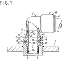
- FIG. 1 is a partially cutaway front sectional view showing an embodiment of a pipe joint according to the present invention.
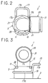
- FIG. 2 is a plan view of the embodiment.
- FIG. 3 is a right side view of the embodiment.
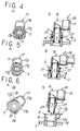
- FIG. 4A is a plan sectional view taken along a line A-A and showing a state of fitting of a stud into a socket in the pipe joint of the invention and FIG. 4B is a partially cutaway front sectional view of the state.
- FIG. 5A is a plan sectional view showing a state of use of the pipe joint of the invention in the same position as FIG. 4A and FIG. 5B is a partially cutaway front sectional view of the state.
- FIG. 6A is a plan sectional view showing a state of detaching of the stud from the socket in the same position as FIG. 4A and FIG. 6B is a partially cutaway front sectional view of the state.
- FIG. 7A is a plan sectional view showing a state of mounting of a stud to a socket in another embodiment of the pipe joint of the invention in the same position as FIG. 4A and FIG. 7B is a plan sectional view showing a state of detaching of the stud from the socket in the same position as FIG. 4A.
- FIG. 8 is a partially cutaway front sectional view of a prior-art pipe joint.
-
- FIGS. 1 to 6 show an embodiment of a pipe joint according to the present invention.
- As specifically shown in FIGS. 1 to 3, the
pipe joint 1 has a substantiallycylindrical socket 5 mounted to afluid pressure device 3 and forming a connecting opening of flow paths and a substantiallycylindrical stud 11 having aflow path 7 for fluid inside thestud 11 and connected by airtightly inserting a tip end portion of thestud 11 into thesocket 5 through an O-ring 9 as a seal member, a jointmain body 15 connected when fitted airtightly over a base end portion of thestud 11 through an O-ring 13 as a seal member, and anelastic clip 17 for locking thestud 11 and thesocket 5 fitted with each other in a connected state. - The
socket 5 is fixed to thefluid pressure device 3 by proper means such as welding and a pair of parallelclip housing grooves members clip 17 are fitted are formed in positions facing each other on an outer side face of thesocket 5. Theclip housing grooves socket 5 and are cut to have such a depth as to reach a hollow portion within thesocket 5. As shown in FIG. 6,shallow retention grooves members above housing grooves outer walls housing grooves clip 17 from dropping when theclip 17 in thehousing grooves outer walls clip 17 about the axis of thesocket 5 to spread the pair of pairedmembers stud 11. - A pair of contact faces 21, 21 formed of flat faces are formed in parallel to each other in positions facing each other at an end portion of the
socket 5 on a side mounted with thestud 11. Two outer faces 28a, 28a of ahexagonal portion 28 of thestud 11 come into contact with the contact faces 21, 21, thereby connecting thestud 11 to thesocket 5 in a state in which rotation of thestud 11 is limited. - The
stud 11 has on an end side thereof a press-fittedportion 22 press-fitted into an opening of the jointmain body 15. Thestud 11 has on an outer periphery of the press-fitted portion 22 alocking portion 23 locked onto an inner peripheral face of the opening of the jointmain body 15 and agroove 24 into which the O-ring 13 is fitted. Thestud 11 has on the other end side thereof agroove 25 into which the O-ring 9 for airtightly providing sealing between thestud 11 and the inner peripheral face of thesocket 5. Thestud 11 has atapered face 26 tapered so as to elastically spread the pairedmembers clip 17 as thestud 11 is inserted into thesocket 5. Moreover, in a position adjacent to a base end portion of thetapered face 26, thestud 11 has alocking groove 27 which corresponds to theclip housing grooves 19 of thesocket 5 and into which theclip 17 is fitted and locked to retain thestud 11 in a state in which coming off of thestud 11 is prevented. - The
stud 11 has thehexagonal portion 28 on the end portion of thestud 11 on a side provided with the press-fittedportion 22 of thestud 11. When thestud 11 is fitted into thesocket 5, the outer faces 28a, 28a of thehexagonal portion 28 face the contact faces 21, 21 of thesocket 5 to suppress rotation of thestud 11 with respect to thesocket 5. - The joint
main body 15 has a shape of an elbow and has atube connecting portion 29 at an end portion of the jointmain body 15 on a side opposite to a side connected to thestud 11. Thetube connecting portion 29 has a known quick-type joint structure having seal material, a locking portion locked by biting into an outer wall of a tube C (both of which are not shown), and arelease member 31 to be pushed into thetube connecting portion 29 to cancel locking of the locking portion and to enable the tube C to be drawn out. However, the joint structure may be other structures as long as the tube C can be connected to the structure. The shape of the jointmain body 15 is not limited to the elbow and a half, a cheese, and the like may be applied to the jointmain body 15. - The
clip 17 is for preventing thestud 11 from coming off from thesocket 5 and has the pair of pairedmembers operating portion 17b for opening and closing the pairedmembers operating portion 17b is formed of a connecting portion for connecting one ends of the pairedmembers operating portion 17b and rotating theclip 17, the pairedmembers clip 17 are spread. - In the
pipe joint 1 having the above structure, in order to attach thestud 11 to thesocket 5 provided to thefluid pressure device 3, as shown in FIGS. 4A and 4B, thestud 11 is inserted and pushed into thesocket 5 to such a position that the taperedface 26 moves while elastically spreading the pairedmembers clip 17 and passes between the pairedmembers members groove 27 of the stud 11 (see FIGS. 5A and 5B). - On the other hand, in order to detach the stud from the
socket 5, as shown in FIGS. 6A and 6B, the operatingportion 17b is held and theclip 17 is rotated about the axis of thesocket 5 and caused to climb onto theouter walls members outer walls members - In this case, because the
clip retention grooves clip housing grooves outer walls clip 17 from coming off from thesocket 5 when theclip 17 is rotated and caused to climb onto theouter walls - As described above, the pipe joint 1 can be attached to and detached from the
fluid pressure device 3 easily and in a short time without necessity of using a tool such as a spanner. Therefore, the operation steps for attaching and detaching the pipe joint 1 to and from the fluid pressure device become easy and operability can be improved. - An alternative embodiment of the
clip 17 is shown in FIGS. 7A and 7B. - Specifically, in a
clip 37, end portions of pairedmembers socket 5 to cross each other and tip end portions of the pairedmembers socket 5 to form an operating portion 37c to be pinched between a thumb and fingers. - With this structure, because the paired
members stud 11 from thesocket 5 more easily. - Although the
stud 11 can be detached from thesocket 5 by only operating the operating portion 37c of theabove clip 37, it is of course possible to detach thestud 11 from thesocket 5 by cooperation between the operating portion 37c and an operatingportion 37b. - According to the pipe joint of the invention that has been described above specifically, the pipe joint can be attached to and detached from the fluid pressure device easily and in a short time without necessity of using a tool such as a spanner. Therefore, the operation steps for attaching and detaching the pipe joint to and from the fluid pressure device become easy and operability can be improved.
Claims (5)
- A pipe joint comprising a cylindrical socket mounted to a fluid pressure device; a cylindrical stud connected to the socket by inserting a tip end portion of the stud into the socket with a seal member therebetween, a joint main body fitted over a base end portion of the stud with a seal member therebetween, and an elastic clip for locking the stud and the socket in the interconnected state, wherein the clip has a pair of paired members which extend generally in parallel with each other, the socket has a pair of parallel clip housing grooves into which the pair of paired members are fitted in opposed positions on an outer face of the socket, the clip housing grooves extending transversely to the socket axis through the socket to a hollow portion therein, and the stud has a face tapered such as to elastically spread the paired members of the clip fitted in the housing grooves as the stud is inserted into the socket and a locking groove formed adjacent to the base end of the tapered face into which the paired members are fitted when the stud is inserted in the socket.
- A pipe joint according to Claim 1, wherein the pipe joint is formed such that, for withdrawal of the stud, the clip is rotated about the socket axis to cause the clip to climb onto an outer wall of the socket which spreads the pair of paired members, and wherein a shallow retention groove is formed on the outer socket wall connected to the housing grooves for receiving the paired member so as to prevent the clip when it has climbed onto the outer wall from dropping.
- A pipe joint according to either Claim 1 or Claim 2 wherein the clip has an operating means comprising a connecting portion for connecting an end portion of each of the pair of paired members together and wherein the end portions of the paired members are bent upward into hook shapes when viewed from the side such that the connecting portion has a different height from the paired members.
- A pipe joint according to any preceding claim, wherein the clip has operating means comprising free end portions of the paired members which extend along an outer face of the socket and cross each other, the tips of the end portions being bent to extend in a direction away from the outer socket face in hook shapes.
- A pipe joint according to any preceding claim, wherein contact faces are formed on the socket and the stud which, when in contact, prevent rotation of the stud.
Applications Claiming Priority (2)
| Application Number | Priority Date | Filing Date | Title |
|---|---|---|---|
| JP18794099 | 1999-07-01 | ||
| JP18794099A JP3561440B2 (en) | 1999-07-01 | 1999-07-01 | Pipe fittings |
Publications (1)
| Publication Number | Publication Date |
|---|---|
| EP1065427A1 true EP1065427A1 (en) | 2001-01-03 |
Family
ID=16214847
Family Applications (1)
| Application Number | Title | Priority Date | Filing Date |
|---|---|---|---|
| EP00305357A Withdrawn EP1065427A1 (en) | 1999-07-01 | 2000-06-26 | Pipe joint |
Country Status (5)
| Country | Link |
|---|---|
| US (1) | US6371528B1 (en) |
| EP (1) | EP1065427A1 (en) |
| JP (1) | JP3561440B2 (en) |
| KR (1) | KR20010049641A (en) |
| CN (1) | CN1125259C (en) |
Cited By (7)
| Publication number | Priority date | Publication date | Assignee | Title |
|---|---|---|---|---|
| WO2003031862A1 (en) * | 2001-10-05 | 2003-04-17 | Bendix Commercial Vehicle Systems Llc | Push-to-connect fittings for air brake reservoirs |
| EP1600683A1 (en) * | 2004-05-19 | 2005-11-30 | ContiTech Schlauch GmbH | Separable coupling box and manufacturing process for a separable coupling box |
| EP1701082A1 (en) * | 2005-03-10 | 2006-09-13 | FTE automotive GmbH | Conduit end portion with overmoulded plug arrangement |
| WO2007036794A1 (en) * | 2005-09-30 | 2007-04-05 | Illinois Tool Works Inc. | Quick connector |
| WO2013012847A1 (en) * | 2011-07-18 | 2013-01-24 | Parker-Hannifin Corporation | Sealing cap |
| EP2293004A3 (en) * | 2009-07-13 | 2015-04-29 | Valeo Klimasysteme GmbH | Coupling assembly for a vehicle air-conditioning unit |
| DE102022114275A1 (en) | 2022-06-07 | 2023-12-07 | Valeo Powertrain Gmbh | Sensor and sensor assembly |
Families Citing this family (29)
| Publication number | Priority date | Publication date | Assignee | Title |
|---|---|---|---|---|
| US6267047B1 (en) * | 1999-08-10 | 2001-07-31 | The Coleman Company, Inc. | Portable griddle stove with dual cooking surfaces |
| SE0004701D0 (en) * | 2000-12-19 | 2000-12-19 | Siemens Elema Ab | Anesthetic vaporizers |
| US6554322B2 (en) * | 2001-05-21 | 2003-04-29 | Thach Duong | Controller valve coupling |
| JP4252785B2 (en) * | 2002-10-01 | 2009-04-08 | 株式会社パイオラックス | Piping connector and manufacturing method thereof |
| JP4291989B2 (en) * | 2002-10-01 | 2009-07-08 | 株式会社パイオラックス | Piping connector |
| FR2855590B1 (en) * | 2003-05-27 | 2006-10-20 | Caillau Ets | QUICK CONNECTOR TIP |
| DE10346712B4 (en) * | 2003-10-08 | 2006-02-02 | Henn Gmbh & Co. Kg | Plug connection for pipe and hose lines with detent spring guide |
| US7650738B2 (en) * | 2005-01-06 | 2010-01-26 | Dave Dietrich | Crop lifter and crop accessory attachment |
| US7438328B2 (en) * | 2005-03-25 | 2008-10-21 | Tokai Rubber Industries, Ltd. | Quick connector |
| DE102006002565A1 (en) * | 2006-01-05 | 2007-07-12 | Alfred Kärcher Gmbh & Co. Kg | Coupling part for connector assembly |
| DE102006002564A1 (en) * | 2006-01-05 | 2007-07-12 | Alfred Kärcher Gmbh & Co. Kg | Plug-in part for connector arrangement |
| US7784504B2 (en) * | 2006-03-06 | 2010-08-31 | Baxter International Inc. | Adapters for use with an anesthetic vaporizer |
| US8522839B2 (en) * | 2006-03-06 | 2013-09-03 | Baxter International Inc. | Adapters for use with an anesthetic vaporizer |
| US8534328B2 (en) * | 2008-04-09 | 2013-09-17 | Baxter International Inc. | Adapters for use with an anesthetic vaporizer |
| US8500088B2 (en) * | 2009-05-20 | 2013-08-06 | Baxter International Inc. | Container and pharmaceutical product |
| KR200459733Y1 (en) * | 2009-07-17 | 2012-04-16 | 말레동현필터시스템 주식회사 | Device for Connecting EGR pipe with Intake Manifold |
| JP2011117541A (en) * | 2009-12-04 | 2011-06-16 | Nissin Kogyo Co Ltd | Pipe connecting structure of fluid actuator |
| EP2597348A1 (en) * | 2011-11-24 | 2013-05-29 | Eaton Germany GmbH | Plug-in connection with a retaining clip |
| KR101440575B1 (en) * | 2014-02-14 | 2014-09-17 | 현대코퍼레이션 주식회사 | Silencer for turbo charger |
| JP6147210B2 (en) | 2014-03-17 | 2017-06-14 | 株式会社ニフコ | Locking mechanism of tubular body |
| DE102015111895A1 (en) * | 2015-07-22 | 2017-01-26 | Dr. Ing. H.C. F. Porsche Aktiengesellschaft | Vehicle component and motor vehicle |
| CN105090650A (en) * | 2015-08-29 | 2015-11-25 | 葫芦岛首钢东华机械有限公司 | Inserting type oil delivery pipe |
| CN106861008B (en) * | 2015-12-14 | 2020-07-17 | 北京谊安医疗系统股份有限公司 | Blind-mate joint |
| CN108240514A (en) * | 2017-12-28 | 2018-07-03 | 国网湖南省电力有限公司 | The fast-assembling jointing of transmission line forest fire water for fire extinguishing band |
| US11137094B2 (en) * | 2018-04-23 | 2021-10-05 | Reliance World Wide Corporation | Clip end device |
| FR3083290B1 (en) | 2018-06-29 | 2021-12-24 | Sogefi Air & Cooling | QUICK CONNECTION SYSTEM AND METHOD OF REALIZATION |
| DE102019004659A1 (en) * | 2019-07-02 | 2021-01-07 | Bomag Gmbh | VALVE LOCKING FOR HYDRAULIC HOSE COUPLINGS, CONSTRUCTION MACHINE AND PROCESS |
| CN113216638B (en) * | 2021-04-16 | 2022-06-03 | 湖南响箭重工科技股份有限公司 | Conveying pipe device, pumping system and pump truck |
| US11796105B2 (en) * | 2021-12-06 | 2023-10-24 | Cooper-Standard Automotive Inc. | Connector assembly for coupling a vessel to a fluid tube |
Citations (6)
| Publication number | Priority date | Publication date | Assignee | Title |
|---|---|---|---|---|
| US3450424A (en) | 1964-12-24 | 1969-06-17 | Wiggins Inc E B | Self-locking coupling |
| US3698747A (en) * | 1971-04-05 | 1972-10-17 | Wilson Gordon Wing | Threadless connector |
| US3753582A (en) * | 1971-11-09 | 1973-08-21 | Anarak Inc | Coupling unit |
| FR2454074A1 (en) * | 1979-04-10 | 1980-11-07 | Comte Paul | Solar powered heat exchanger - has lateral cylindrical collectors joined by parallel channels with male and female end connections |
| EP0327441A1 (en) * | 1988-02-02 | 1989-08-09 | Hutchinson | Heat exchanger |
| US5607087A (en) * | 1994-09-19 | 1997-03-04 | Wery; Shawn D. | Pressurized fluid dispensing device |
Family Cites Families (7)
| Publication number | Priority date | Publication date | Assignee | Title |
|---|---|---|---|---|
| US4009896A (en) * | 1976-05-10 | 1977-03-01 | General Motors Corporation | Quick connect coupling |
| US4526411A (en) * | 1980-10-29 | 1985-07-02 | Proprietary Technology, Inc. | Swivelable quick connector assembly |
| DE3531926A1 (en) * | 1985-09-07 | 1987-03-19 | Kugelfischer G Schaefer & Co | DETACHABLE CONNECTOR |
| US4884829A (en) * | 1986-09-16 | 1989-12-05 | Johannes Schaefer Vorm. Stettiner Schraubenwerke Gmbh & Co. Kg | Plug-in connection for connecting tube and host lines in particular for use in tube-line systems of motor vehicles |
| JPH0686916B2 (en) | 1988-11-01 | 1994-11-02 | エスエムシー株式会社 | Pipe fitting |
| JPH0648075B2 (en) | 1990-04-16 | 1994-06-22 | エスエムシー株式会社 | Pipe fitting |
| DE4310192C2 (en) * | 1992-07-28 | 2001-05-31 | Matsushita Electric Works Ltd | Quick connection coupling |
-
1999
- 1999-07-01 JP JP18794099A patent/JP3561440B2/en not_active Expired - Fee Related
-
2000
- 2000-06-22 US US09/599,443 patent/US6371528B1/en not_active Expired - Lifetime
- 2000-06-26 EP EP00305357A patent/EP1065427A1/en not_active Withdrawn
- 2000-06-28 KR KR1020000035916A patent/KR20010049641A/en not_active Ceased
- 2000-06-30 CN CN00119908A patent/CN1125259C/en not_active Expired - Fee Related
Patent Citations (6)
| Publication number | Priority date | Publication date | Assignee | Title |
|---|---|---|---|---|
| US3450424A (en) | 1964-12-24 | 1969-06-17 | Wiggins Inc E B | Self-locking coupling |
| US3698747A (en) * | 1971-04-05 | 1972-10-17 | Wilson Gordon Wing | Threadless connector |
| US3753582A (en) * | 1971-11-09 | 1973-08-21 | Anarak Inc | Coupling unit |
| FR2454074A1 (en) * | 1979-04-10 | 1980-11-07 | Comte Paul | Solar powered heat exchanger - has lateral cylindrical collectors joined by parallel channels with male and female end connections |
| EP0327441A1 (en) * | 1988-02-02 | 1989-08-09 | Hutchinson | Heat exchanger |
| US5607087A (en) * | 1994-09-19 | 1997-03-04 | Wery; Shawn D. | Pressurized fluid dispensing device |
Cited By (9)
| Publication number | Priority date | Publication date | Assignee | Title |
|---|---|---|---|---|
| WO2003031862A1 (en) * | 2001-10-05 | 2003-04-17 | Bendix Commercial Vehicle Systems Llc | Push-to-connect fittings for air brake reservoirs |
| US6679527B2 (en) | 2001-10-05 | 2004-01-20 | Bendix Commercial Vehicle Systems Llc | Push-to-connect fittings for air brake reservoirs |
| EP1600683A1 (en) * | 2004-05-19 | 2005-11-30 | ContiTech Schlauch GmbH | Separable coupling box and manufacturing process for a separable coupling box |
| EP1701082A1 (en) * | 2005-03-10 | 2006-09-13 | FTE automotive GmbH | Conduit end portion with overmoulded plug arrangement |
| WO2007036794A1 (en) * | 2005-09-30 | 2007-04-05 | Illinois Tool Works Inc. | Quick connector |
| US7695024B2 (en) | 2005-09-30 | 2010-04-13 | Itw Sverige Ab | Quick connector |
| EP2293004A3 (en) * | 2009-07-13 | 2015-04-29 | Valeo Klimasysteme GmbH | Coupling assembly for a vehicle air-conditioning unit |
| WO2013012847A1 (en) * | 2011-07-18 | 2013-01-24 | Parker-Hannifin Corporation | Sealing cap |
| DE102022114275A1 (en) | 2022-06-07 | 2023-12-07 | Valeo Powertrain Gmbh | Sensor and sensor assembly |
Also Published As
| Publication number | Publication date |
|---|---|
| US6371528B1 (en) | 2002-04-16 |
| JP3561440B2 (en) | 2004-09-02 |
| CN1125259C (en) | 2003-10-22 |
| KR20010049641A (en) | 2001-06-15 |
| CN1290831A (en) | 2001-04-11 |
| JP2001012664A (en) | 2001-01-16 |
Similar Documents
| Publication | Publication Date | Title |
|---|---|---|
| US6371528B1 (en) | Fluid pressure device pipe joint | |
| JP2794365B2 (en) | Plug-in fittings for connecting tubes to pipes | |
| KR200267995Y1 (en) | The pipe coupling structure | |
| GB2339873A (en) | A plug-in coupling for connecting two fluid pipelines | |
| KR20050062560A (en) | Connector device for pipes | |
| US20160138631A1 (en) | Coupling device | |
| JP3253965B2 (en) | Quick connector | |
| US11384874B2 (en) | Fitting device for making connection tube that can fine position adjustment of the tube | |
| JP7305980B2 (en) | Dust cap for eye joint | |
| US9845906B2 (en) | Release clip | |
| JP4066397B2 (en) | Tube connection method | |
| CA3058575A1 (en) | Connector for piping networks | |
| JPH01275991A (en) | Pipe fitting | |
| KR100446186B1 (en) | tube coupler | |
| JP4034433B2 (en) | Tube connection structure | |
| JP4727077B2 (en) | Plug-in fittings | |
| KR0156362B1 (en) | Connection structure of fuel line connector of automobile | |
| JPH04125389A (en) | Fitting for flexible tubes | |
| JP2000320768A (en) | Connection plug device for pipe member | |
| JPH11101380A (en) | One-touch connection device for focusing hose | |
| KR200341206Y1 (en) | a hose coupling pipe for a sprinkler | |
| JP5174484B2 (en) | Detachment prevention pipe joint and lock ring holding spring used for the pipe joint | |
| JPH0237355Y2 (en) | ||
| JP3044015B2 (en) | Connection structure of pneumatic conditioner and unit for pneumatic conditioner | |
| JPH0538312Y2 (en) |
Legal Events
| Date | Code | Title | Description |
|---|---|---|---|
| PUAI | Public reference made under article 153(3) epc to a published international application that has entered the european phase |
Free format text: ORIGINAL CODE: 0009012 |
|
| 17P | Request for examination filed |
Effective date: 20000706 |
|
| AK | Designated contracting states |
Kind code of ref document: A1 Designated state(s): DE FR GB |
|
| AX | Request for extension of the european patent |
Free format text: AL;LT;LV;MK;RO;SI |
|
| AKX | Designation fees paid |
Free format text: DE FR GB |
|
| 17Q | First examination report despatched |
Effective date: 20050513 |
|
| 17Q | First examination report despatched |
Effective date: 20050513 |
|
| GRAP | Despatch of communication of intention to grant a patent |
Free format text: ORIGINAL CODE: EPIDOSNIGR1 |
|
| STAA | Information on the status of an ep patent application or granted ep patent |
Free format text: STATUS: THE APPLICATION IS DEEMED TO BE WITHDRAWN |
|
| 18D | Application deemed to be withdrawn |
Effective date: 20101008 |