EP1065368A2 - Fuel injector - Google Patents
Fuel injector Download PDFInfo
- Publication number
- EP1065368A2 EP1065368A2 EP00305414A EP00305414A EP1065368A2 EP 1065368 A2 EP1065368 A2 EP 1065368A2 EP 00305414 A EP00305414 A EP 00305414A EP 00305414 A EP00305414 A EP 00305414A EP 1065368 A2 EP1065368 A2 EP 1065368A2
- Authority
- EP
- European Patent Office
- Prior art keywords
- fuel
- needle
- chamber
- control
- control chamber
- Prior art date
- Legal status (The legal status is an assumption and is not a legal conclusion. Google has not performed a legal analysis and makes no representation as to the accuracy of the status listed.)
- Withdrawn
Links
- 239000000446 fuel Substances 0.000 title claims abstract description 95
- 238000002347 injection Methods 0.000 claims abstract description 30
- 239000007924 injection Substances 0.000 claims abstract description 30
- 238000005086 pumping Methods 0.000 claims description 11
- 238000005553 drilling Methods 0.000 description 4
- 238000002485 combustion reaction Methods 0.000 description 1
- 230000000694 effects Effects 0.000 description 1
- 230000004043 responsiveness Effects 0.000 description 1
- 238000007493 shaping process Methods 0.000 description 1
Images
Classifications
-
- F—MECHANICAL ENGINEERING; LIGHTING; HEATING; WEAPONS; BLASTING
- F02—COMBUSTION ENGINES; HOT-GAS OR COMBUSTION-PRODUCT ENGINE PLANTS
- F02M—SUPPLYING COMBUSTION ENGINES IN GENERAL WITH COMBUSTIBLE MIXTURES OR CONSTITUENTS THEREOF
- F02M57/00—Fuel-injectors combined or associated with other devices
- F02M57/02—Injectors structurally combined with fuel-injection pumps
-
- F—MECHANICAL ENGINEERING; LIGHTING; HEATING; WEAPONS; BLASTING
- F02—COMBUSTION ENGINES; HOT-GAS OR COMBUSTION-PRODUCT ENGINE PLANTS
- F02M—SUPPLYING COMBUSTION ENGINES IN GENERAL WITH COMBUSTIBLE MIXTURES OR CONSTITUENTS THEREOF
- F02M47/00—Fuel-injection apparatus operated cyclically with fuel-injection valves actuated by fluid pressure
- F02M47/02—Fuel-injection apparatus operated cyclically with fuel-injection valves actuated by fluid pressure of accumulator-injector type, i.e. having fuel pressure of accumulator tending to open, and fuel pressure in other chamber tending to close, injection valves and having means for periodically releasing that closing pressure
- F02M47/027—Electrically actuated valves draining the chamber to release the closing pressure
-
- F—MECHANICAL ENGINEERING; LIGHTING; HEATING; WEAPONS; BLASTING
- F02—COMBUSTION ENGINES; HOT-GAS OR COMBUSTION-PRODUCT ENGINE PLANTS
- F02M—SUPPLYING COMBUSTION ENGINES IN GENERAL WITH COMBUSTIBLE MIXTURES OR CONSTITUENTS THEREOF
- F02M59/00—Pumps specially adapted for fuel-injection and not provided for in groups F02M39/00 -F02M57/00, e.g. rotary cylinder-block type of pumps
- F02M59/20—Varying fuel delivery in quantity or timing
- F02M59/36—Varying fuel delivery in quantity or timing by variably-timed valves controlling fuel passages to pumping elements or overflow passages
- F02M59/366—Valves being actuated electrically
-
- F—MECHANICAL ENGINEERING; LIGHTING; HEATING; WEAPONS; BLASTING
- F02—COMBUSTION ENGINES; HOT-GAS OR COMBUSTION-PRODUCT ENGINE PLANTS
- F02M—SUPPLYING COMBUSTION ENGINES IN GENERAL WITH COMBUSTIBLE MIXTURES OR CONSTITUENTS THEREOF
- F02M2200/00—Details of fuel-injection apparatus, not otherwise provided for
- F02M2200/21—Fuel-injection apparatus with piezoelectric or magnetostrictive elements
Definitions
- This invention relates to a fuel injector for use in delivering fuel under high pressure to a combustion space of an associated engine.
- the invention relates, in particular, to a fuel injector of the type including a pump, the pump supplying fuel exclusively to the injection nozzle of the injector, and not to the nozzles of other injectors associated with the engine.
- the pump typically forms part of the injector, being rigidly mounted upon or secured to the injection nozzle, but arrangements are also possible in which the pump is spaced from the injection nozzle, a high pressure fuel line connecting the pump chamber of the pump to the nozzle of the injector.
- the timing of fuel injection is controlled independently of the timing of commencement of fuel pressurisation by the pump by controlling the fuel pressure within a control chamber, a surface associated with the needle of the injection nozzle being exposed to the fuel pressure within the control chamber.
- the magnitude of a force urging the valve needle towards its seating can be controlled.
- the control of the control chamber pressure is achieved using an electromagnetically actuable three way valve operable to permit communication between the control chamber and either a supply passage containing fuel under pressure or a drain passage which communicates, in use, with a relatively low pressure fuel reservoir.
- a fuel injector comprising a valve needle slidable within a bore formed in a nozzle and engageable with a seating to control delivery of fuel from the bore, and a supply passage for supplying fuel under high pressure to the bore, the needle having associated therewith a surface exposed to the fuel pressure within a control chamber, the control chamber communicating, continuously, through an inlet passage with the supply passage, the control chamber further communicating, through an outlet passage, with an injection control valve arranged to control communication between the control chamber and a drain port, wherein the inlet and outlet passages are shaped to restrict the rate at which fuel can flow to and from the control chamber.
- a fuel delivery chamber connected with the supply passage is provided in the nozzle
- the needle has at least one thrust surface exposed to pressure in the fuel delivery chamber and arranged, in use, to urge the needle away from the seating, and the surface exposed to fuel pressure within the control chamber is arranged to act on the needle in a direction tending to urge the needle towards the seating.
- the surface exposed to fuel pressure within the control chamber has a greater effective area than the effective area of said at least one thrust surface of the needle.
- the surface exposed to pressure within the control chamber is conveniently defined by a surface of a piston engageable with the needle.
- the injection control valve may be an electromagnetically actuable valve or a piezoelectrically actuable valve.
- the injector may further comprise a pressurisation control valve for controlling communication between a pumping chamber of a fuel pump associated with the injector and a low pressure feed port.
- the pressurisation control valve is arranged as a spill valve to allow fuel from the pumping chamber to be pumped back to the feed port when fuel delivery from the nozzle is not required.
- the pump may be rigidly mounted upon the nozzle.
- the pump and nozzle may be spaced apart from one another, the supply passage being defined, at least in part, by a high pressure pipe.
- the fuel injector illustrated in the accompanying drawings takes the form of a unit pump/injector and comprises a nozzle body 10 having a blind bore 11 formed therein within which a needle 12 is slidable.
- the needle 12 is engageable with a seating defined adjacent the blind end of the bore 11 to control fuel flow past the seating from the bore 11 to a plurality of outlet openings 13 located downstream of the seating.
- the needle 12 includes an upper region of diameter substantially equal to the diameter of the adjacent part of the bore 11, the cooperation between these parts of the needle 12 and the bore 11 guiding the needle 12 for sliding movement within the bore 11.
- This part of the bore 11 includes a region of enlarged diameter defining an annular gallery 14. Fuel from the annular gallery 14 is able to flow to a delivery chamber 15 defined between the needle 12 and the bore 11 adjacent the seating through flutes 16 formed in the needle 12.
- the nozzle body 10 abuts a piston housing 17 provided with a blind bore of stepped form, a piston 18 being slidable within the bore adjacent the blind end thereof.
- the piston 18 includes a projection 19 which is engageable with a projection extending from the upper end of the needle 12, in the orientation illustrated.
- the bore further houses a spring 20 which is seated against a step of the bore and which abuts a spring abutment member 20 a located between the spring 20 and the needle 12. The spring 20 therefore applies, via the spring abutment member 20 a , a relatively small force to the needle 12 to urge the needle 12 towards the seating.
- the piston housing 17 abuts a valve housing 21 provided with a through bore 22 within which a valve member 23 is slidable.
- the valve member 23 includes a region 24 of relatively large diameter which is engageable with a seating defined adjacent an end of the bore 22 to control communication between an annular chamber 25 defined between the valve member 23 and the bore 22 and an armature chamber 26 defined by a recess formed in an end face of the valve housing 21.
- the armature chamber 26 houses an armature 27 moveable under the control of an electromagnetic actuator 28 located within an actuator housing 29 to move the valve member 23 between a position in which it engages its seating and a position in which it is lifted from its seating.
- the actuator 28 includes a spring arranged to urge the valve member 23 into engagement with its seating when the actuator is not energised.
- the valve housing 21 and piston housing 17 are provided with drillings forming a passage 30 whereby the bore containing the spring 20 and the lower end of the bore 22 are connected to the armature chamber 26.
- the armature chamber 26 is connected through a passage (not shown) with a backleak or drain port of the injector which communicates, in use, with a relatively low pressure fuel reservoir (not shown).
- the actuator housing 29 abuts a pump body 31 provided with a bore 32 within which a pump plunger 33 is reciprocable under the action of a cam and tappet arrangement 34 against a return spring 35.
- the bore 32 and plunger 33 together define a pumping chamber 36 which communicates through a supply passage 37 formed by drillings provided in the actuator housing, the valve housing, and piston housing and the nozzle body with the annular gallery 14.
- the supply passage 37 communicates through an inlet passage 38 with a control chamber 39 defined between the piston 18 and the blind end of the bore within which the piston 18 is slidable.
- the inlet passage 38 is defined, in part, by a drilling 38 a of small diameter.
- control chamber 39 is in constant communication with the supply passage 37, and that the rate at which fuel is able to flow to the control chamber 39 is restricted.
- An outlet passage 40 including a drilling 40 a of small diameter provides a constant, restricted flow path between the control chamber 39 and the annular chamber 25.
- An electromagnetically actuable spill valve 41 is mounted upon the pump body 31.
- the spill valve 41 includes a valve member 42 which extends transversely to the axis of the needle 12 through a bore 42 a .
- a plug member 44 closes the bore 42 a at the end of the valve needle 42 remote from the spill valve 41.
- the valve member 42 is engageable with a seating to control communication between the pump chamber 36 and a feed port (not shown) by means of a passage 43.
- the feed port communicates, in use, with the relatively low pressure fuel reservoir.
- a cap nut is used, in the conventional manner, to secure the various parts of the injector to one another.
- the net effect of the forces applied by the fuel pressure and the action of the spring 20 results in the needle 12 being held against its seating thus fuel injection does not take place.
- the force applied by the spring 20 is, as mentioned hereinbefore, relatively low but is sufficient to hold the needle 12 in engagement with its seating against cylinder pressure, in use.
- the spill valve 41 In order to commence pressurisation of fuel, the spill valve 41 is energised, moving the spill valve member 42 into engagement with its seating, preventing further fuel from being displaced to the low pressure reservoir. As fuel is no longer displaced in the aforesaid manner, continued inward movement of the plunger 33 pressurises the fuel within the pumping chamber 36 and bores in communication therewith. The increase in the fuel pressure occurs both in the delivery chamber 15 and in the control chamber 39, urging the piston 18 into engagement with the needle 12, and as the effective area of the surface of the piston 18 exposed to the fuel pressure within the control chamber 39 is greater than that of the needle 12 exposed to the fuel pressure within the delivery chamber 15, the needle 12 is held in engagement with its seating by the fuel under pressure.
- the timing at which the spill valve is closed is chosen such that a desired fuel pressure is achieved within the delivery chamber 15 at the instant at which fuel injection is to commence.
- the valve member 23 In order to commence injection, the valve member 23 is lifted from its seating by energising the actuator 28. Such movement allows fuel to escape from the control chamber 39, relieving the fuel pressure therein.
- the values of the restrictions to fuel flow defined by the inlet and outlet passages 38, 40 are chosen to ensure that the fuel pressure within the control chamber 39 falls at a desired rate.
- the reduction in fuel pressure reduces the magnitude of the force applied to the needle 12 by the piston 18, and a point will be reached beyond which the needle 12 is able to lift away from its seating, lifting the piston 18, and allowing fuel to flow to the outlet openings 13. Fuel injection thus takes place.
- the distance through which the needle 12 can lift is limited by the piston 18 moving into engagement with a stop formed integrally with the piston housing 17.
- Injection can be interrupted, if desired, by deenergising the actuator 28 to allow the valve member 23 to move into engagement with its seating, breaking the flow path between the control chamber 39 and the low pressure reservoir.
- the control chamber 39 is in constant communication with the supply passage 37, the control chamber pressure rises, increasing the magnitude of the downward force applied to the needle 12, and a point will be reached beyond which the needle 12 returns into engagement with its seating.
- Injection can be restored by reenergising the actuator 28 and terminated by, again, deenergising the actuator 28.
- the injector can be used to supply a pilot fuel injection or a post-injection followed or preceded respectively by a main fuel injection, and this is advantageous in that noise and emissions levels can be reduced.
- the spill valve 41 On terminating injection at the end of an injection cycle, the spill valve 41 is conveniently opened to relieve the fuel pressure within the pumping chamber 36. At about the same time as the spill valve 41 is opened, and preferably just before, the control valve 24 is closed. This has the result that the forces acting on the needle 12 urging the needle 12 away from the seating are reduced rapidly, assisting the fuel pressure within the control chamber 39 and giving rise to a rapid termination of injection. This is particularly advantageous where a main injection is to be terminated.
- the injector described hereinbefore is advantageous in that it can be operated in a number of ways.
- the pressure can be maintained as substantially a desired level, and accurate control of the injection pressure can be achieved.
- Accurate control over the timing of fuel injection, at both the commencement and termination of injection can also be achieved.
- Selection of the sizes of the restrictions to fuel flow defined by the inlet and outlet passages allows the responsiveness of the injector at both the commencement and termination of injection to be tuned, permitting initial injection rate shaping.
- valve member 23 need not be controlled by means of an electromagnetic actuator, but alternatively may be controlled by means of a piezoelectric actuator.
Landscapes
- Engineering & Computer Science (AREA)
- Chemical & Material Sciences (AREA)
- Combustion & Propulsion (AREA)
- Mechanical Engineering (AREA)
- General Engineering & Computer Science (AREA)
- Physics & Mathematics (AREA)
- Fluid Mechanics (AREA)
- Fuel-Injection Apparatus (AREA)
Abstract
Description
- This invention relates to a fuel injector for use in delivering fuel under high pressure to a combustion space of an associated engine. The invention relates, in particular, to a fuel injector of the type including a pump, the pump supplying fuel exclusively to the injection nozzle of the injector, and not to the nozzles of other injectors associated with the engine. The pump typically forms part of the injector, being rigidly mounted upon or secured to the injection nozzle, but arrangements are also possible in which the pump is spaced from the injection nozzle, a high pressure fuel line connecting the pump chamber of the pump to the nozzle of the injector.
- In known pump injectors, for example as shown in EP 0840003, the timing of fuel injection is controlled independently of the timing of commencement of fuel pressurisation by the pump by controlling the fuel pressure within a control chamber, a surface associated with the needle of the injection nozzle being exposed to the fuel pressure within the control chamber. By appropriate control of the fuel pressure within the control chamber, the magnitude of a force urging the valve needle towards its seating can be controlled. The control of the control chamber pressure is achieved using an electromagnetically actuable three way valve operable to permit communication between the control chamber and either a supply passage containing fuel under pressure or a drain passage which communicates, in use, with a relatively low pressure fuel reservoir.
- It is an object of the invention to provide a fuel injector in which the degree of control over injection is improved.
- According to the present invention there is provided a fuel injector comprising a valve needle slidable within a bore formed in a nozzle and engageable with a seating to control delivery of fuel from the bore, and a supply passage for supplying fuel under high pressure to the bore, the needle having associated therewith a surface exposed to the fuel pressure within a control chamber, the control chamber communicating, continuously, through an inlet passage with the supply passage, the control chamber further communicating, through an outlet passage, with an injection control valve arranged to control communication between the control chamber and a drain port, wherein the inlet and outlet passages are shaped to restrict the rate at which fuel can flow to and from the control chamber.
- Preferably, a fuel delivery chamber connected with the supply passage is provided in the nozzle, the needle has at least one thrust surface exposed to pressure in the fuel delivery chamber and arranged, in use, to urge the needle away from the seating, and the surface exposed to fuel pressure within the control chamber is arranged to act on the needle in a direction tending to urge the needle towards the seating.
- Preferably also, the surface exposed to fuel pressure within the control chamber has a greater effective area than the effective area of said at least one thrust surface of the needle.
- The surface exposed to pressure within the control chamber is conveniently defined by a surface of a piston engageable with the needle.
- The injection control valve may be an electromagnetically actuable valve or a piezoelectrically actuable valve.
- The injector may further comprise a pressurisation control valve for controlling communication between a pumping chamber of a fuel pump associated with the injector and a low pressure feed port.
- Conveniently, the pressurisation control valve is arranged as a spill valve to allow fuel from the pumping chamber to be pumped back to the feed port when fuel delivery from the nozzle is not required.
- The pump may be rigidly mounted upon the nozzle. Alternatively, the pump and nozzle may be spaced apart from one another, the supply passage being defined, at least in part, by a high pressure pipe.
- The invention will further be described, by way of example, with reference to the accompanying drawings, in which:
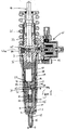
- Figure 1 is a sectional view illustrating a fuel injector in accordance with an embodiment of the invention; and
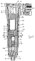
- Figure 2 is an enlargement of part of Figure 1.
-
- The fuel injector illustrated in the accompanying drawings takes the form of a unit pump/injector and comprises a nozzle body 10 having a blind bore 11 formed therein within which a
needle 12 is slidable. Theneedle 12 is engageable with a seating defined adjacent the blind end of the bore 11 to control fuel flow past the seating from the bore 11 to a plurality ofoutlet openings 13 located downstream of the seating. - The
needle 12 includes an upper region of diameter substantially equal to the diameter of the adjacent part of the bore 11, the cooperation between these parts of theneedle 12 and the bore 11 guiding theneedle 12 for sliding movement within the bore 11. This part of the bore 11 includes a region of enlarged diameter defining anannular gallery 14. Fuel from theannular gallery 14 is able to flow to adelivery chamber 15 defined between theneedle 12 and the bore 11 adjacent the seating throughflutes 16 formed in theneedle 12. - The nozzle body 10 abuts a
piston housing 17 provided with a blind bore of stepped form, apiston 18 being slidable within the bore adjacent the blind end thereof. Thepiston 18 includes aprojection 19 which is engageable with a projection extending from the upper end of theneedle 12, in the orientation illustrated. The bore further houses aspring 20 which is seated against a step of the bore and which abuts a spring abutment member 20a located between thespring 20 and theneedle 12. Thespring 20 therefore applies, via the spring abutment member 20a, a relatively small force to theneedle 12 to urge theneedle 12 towards the seating. - The piston housing 17 abuts a
valve housing 21 provided with athrough bore 22 within which avalve member 23 is slidable. Thevalve member 23 includes aregion 24 of relatively large diameter which is engageable with a seating defined adjacent an end of thebore 22 to control communication between anannular chamber 25 defined between thevalve member 23 and thebore 22 and anarmature chamber 26 defined by a recess formed in an end face of thevalve housing 21. Thearmature chamber 26 houses anarmature 27 moveable under the control of anelectromagnetic actuator 28 located within anactuator housing 29 to move thevalve member 23 between a position in which it engages its seating and a position in which it is lifted from its seating. Theactuator 28 includes a spring arranged to urge thevalve member 23 into engagement with its seating when the actuator is not energised. - The
valve housing 21 andpiston housing 17 are provided with drillings forming apassage 30 whereby the bore containing thespring 20 and the lower end of thebore 22 are connected to thearmature chamber 26. Thearmature chamber 26 is connected through a passage (not shown) with a backleak or drain port of the injector which communicates, in use, with a relatively low pressure fuel reservoir (not shown). As a result, theneedle 12,piston 18 andvalve member 23 are free to move without becoming hydraulically locked. - The actuator housing 29 abuts a
pump body 31 provided with abore 32 within which apump plunger 33 is reciprocable under the action of a cam and tappetarrangement 34 against areturn spring 35. Thebore 32 andplunger 33 together define apumping chamber 36 which communicates through asupply passage 37 formed by drillings provided in the actuator housing, the valve housing, and piston housing and the nozzle body with theannular gallery 14. Thesupply passage 37 communicates through aninlet passage 38 with acontrol chamber 39 defined between thepiston 18 and the blind end of the bore within which thepiston 18 is slidable. Theinlet passage 38 is defined, in part, by a drilling 38a of small diameter. It will be appreciated, therefore, that thecontrol chamber 39 is in constant communication with thesupply passage 37, and that the rate at which fuel is able to flow to thecontrol chamber 39 is restricted. Anoutlet passage 40 including adrilling 40a of small diameter provides a constant, restricted flow path between thecontrol chamber 39 and theannular chamber 25. - An electromagnetically
actuable spill valve 41 is mounted upon thepump body 31. Thespill valve 41 includes avalve member 42 which extends transversely to the axis of theneedle 12 through a bore 42a. Aplug member 44 closes the bore 42a at the end of thevalve needle 42 remote from thespill valve 41. Thevalve member 42 is engageable with a seating to control communication between thepump chamber 36 and a feed port (not shown) by means of apassage 43. The feed port communicates, in use, with the relatively low pressure fuel reservoir. A cap nut is used, in the conventional manner, to secure the various parts of the injector to one another. - In use, with the feed port communicating through appropriate passages with the relatively low pressure fuel reservoir, with the actuators of both valves deenergised, and with the
plunger 33 at its innermost position, movement of the cam and tappet arrangement allows theplunger 33 to move under the action of thereturn spring 35 to draw fuel past thespill valve member 42 into thepumping chamber 36. The movement of theplunger 33 therefore charges thepumping chamber 36 with fuel at a relatively low pressure. During this phase in the operation of the injector, the fuel pressure within thedelivery chamber 15 acting upon angled thrust surfaces of theneedle 12 is low and fuel pressure within thecontrol chamber 39 is sufficient to hold theprojection 19 of thepiston 18 in engagement with theneedle 12. The net effect of the forces applied by the fuel pressure and the action of thespring 20 results in theneedle 12 being held against its seating thus fuel injection does not take place. The force applied by thespring 20 is, as mentioned hereinbefore, relatively low but is sufficient to hold theneedle 12 in engagement with its seating against cylinder pressure, in use. - Once the
plunger 33 reaches its outermost position, inward movement of the plunger commences. Provided thespill valve 41 is still deenergised, thevalve member 42 thereof remains spaced from its seating, thus fuel is able to flow from the pumping chamber back through the feed port to the fuel reservoir. As fuel is displaced by the movement of theplunger 33 to the low pressure reservoir, it will be appreciated that theneedle 12 does not move and injection of fuel does not commence. - In order to commence pressurisation of fuel, the
spill valve 41 is energised, moving thespill valve member 42 into engagement with its seating, preventing further fuel from being displaced to the low pressure reservoir. As fuel is no longer displaced in the aforesaid manner, continued inward movement of theplunger 33 pressurises the fuel within thepumping chamber 36 and bores in communication therewith. The increase in the fuel pressure occurs both in thedelivery chamber 15 and in thecontrol chamber 39, urging thepiston 18 into engagement with theneedle 12, and as the effective area of the surface of thepiston 18 exposed to the fuel pressure within thecontrol chamber 39 is greater than that of theneedle 12 exposed to the fuel pressure within thedelivery chamber 15, theneedle 12 is held in engagement with its seating by the fuel under pressure. - The timing at which the spill valve is closed is chosen such that a desired fuel pressure is achieved within the
delivery chamber 15 at the instant at which fuel injection is to commence. In order to commence injection, thevalve member 23 is lifted from its seating by energising theactuator 28. Such movement allows fuel to escape from thecontrol chamber 39, relieving the fuel pressure therein. The values of the restrictions to fuel flow defined by the inlet andoutlet passages control chamber 39 falls at a desired rate. The reduction in fuel pressure reduces the magnitude of the force applied to theneedle 12 by thepiston 18, and a point will be reached beyond which theneedle 12 is able to lift away from its seating, lifting thepiston 18, and allowing fuel to flow to theoutlet openings 13. Fuel injection thus takes place. The distance through which theneedle 12 can lift is limited by thepiston 18 moving into engagement with a stop formed integrally with thepiston housing 17. - Injection can be interrupted, if desired, by deenergising the
actuator 28 to allow thevalve member 23 to move into engagement with its seating, breaking the flow path between thecontrol chamber 39 and the low pressure reservoir. As thecontrol chamber 39 is in constant communication with thesupply passage 37, the control chamber pressure rises, increasing the magnitude of the downward force applied to theneedle 12, and a point will be reached beyond which theneedle 12 returns into engagement with its seating. Injection can be restored by reenergising theactuator 28 and terminated by, again, deenergising theactuator 28. It will be appreciated that, in this manner, the injector can be used to supply a pilot fuel injection or a post-injection followed or preceded respectively by a main fuel injection, and this is advantageous in that noise and emissions levels can be reduced. - On terminating injection at the end of an injection cycle, the
spill valve 41 is conveniently opened to relieve the fuel pressure within the pumpingchamber 36. At about the same time as thespill valve 41 is opened, and preferably just before, thecontrol valve 24 is closed. This has the result that the forces acting on theneedle 12 urging theneedle 12 away from the seating are reduced rapidly, assisting the fuel pressure within thecontrol chamber 39 and giving rise to a rapid termination of injection. This is particularly advantageous where a main injection is to be terminated. - The injector described hereinbefore is advantageous in that it can be operated in a number of ways. For example, by appropriate control of the spill valve, the pressure can be maintained as substantially a desired level, and accurate control of the injection pressure can be achieved. Accurate control over the timing of fuel injection, at both the commencement and termination of injection, can also be achieved. Selection of the sizes of the restrictions to fuel flow defined by the inlet and outlet passages allows the responsiveness of the injector at both the commencement and termination of injection to be tuned, permitting initial injection rate shaping.
- Although the description hereinbefore is of a fuel injector of the type in which a pump and a nozzle are rigidly secured to one another, it will be appreciated that these integers could be spaced apart from one another, a suitable fuel pipe being used to transmit fuel under pressure from the pumping chamber of the pump to the nozzle. It will further be appreciated that movement of the
valve member 23 need not be controlled by means of an electromagnetic actuator, but alternatively may be controlled by means of a piezoelectric actuator.
Claims (9)
- A fuel injector comprising a valve needle (12) slidable within a bore (11) formed in a nozzle (10) and engageable with a seating to control delivery of fuel from the bore (11) and a supply passage (37) for supplying fuel under high pressure to the bore (11), the needle (12) having associated therewith a surface exposed to fuel pressure within a control chamber (39), the control chamber (39) communicating, continuously, through an inlet passage (38) with the supply passage (37), the control chamber (39) further communicating, through an outlet passage (40), with an injection control valve (21-25) arranged to control communication between the control chamber (39) and a drain port, wherein the inlet and outlet passages (38 and 40) are shaped to restrict the rate at which fuel can flow to and from the control chamber (39).
- A fuel injector as claimed in claim 1, wherein a fuel delivery chamber (15) connected with the supply passage (37) is provided in the nozzle (10), the needle (12) has at least one thrust surface exposed to pressure in the fuel delivery chamber (15) and arranged, in use, to urge the needle (12) away from the seating, and the surface exposed to fuel pressure within the control chamber (39) is arranged to act on the needle (12) in a direction tending to urge the needle (12) towards the seating.
- A fuel injector as claimed in claim 2, wherein the surface exposed to fuel pressure within the control chamber (39) has a greater effective area than the effective area of said at least one thrust surface of the needle (12).
- A fuel injector as claimed in claim 1, 2 or 3, wherein the surface associated with the needle (12) is defined by a surface of a piston (18) adapted to engage with the needle (12).
- A fuel injector as claimed in any preceding claim, wherein an actuator (28) is provided for actuating the injection control valve (21-25).
- A fuel injector as claimed in claim 5, wherein the actuator (28) is an electromagnetic actuator.
- A fuel injector as claimed in claim 5, wherein the actuator is a piezoelectric actuator.
- A fuel injector as claimed in claim 7, comprising a pressurisation control valve (41) for controlling communication between a pumping chamber (36) of a fuel pump associated with the injector and a low pressure feed port.
- A fuel actuator as claimed in claim 8, wherein the control valve (41) is arranged as a spill valve to allow fuel from the pumping chamber (36) to be pumped back to the feed port when fuel delivery from the nozzle (12) is not required.
Applications Claiming Priority (2)
| Application Number | Priority Date | Filing Date | Title |
|---|---|---|---|
| GBGB9915118.5A GB9915118D0 (en) | 1999-06-30 | 1999-06-30 | Fuel injector |
| GB9915118 | 1999-06-30 |
Publications (2)
| Publication Number | Publication Date |
|---|---|
| EP1065368A2 true EP1065368A2 (en) | 2001-01-03 |
| EP1065368A3 EP1065368A3 (en) | 2002-07-31 |
Family
ID=10856227
Family Applications (1)
| Application Number | Title | Priority Date | Filing Date |
|---|---|---|---|
| EP00305414A Withdrawn EP1065368A3 (en) | 1999-06-30 | 2000-06-28 | Fuel injector |
Country Status (2)
| Country | Link |
|---|---|
| EP (1) | EP1065368A3 (en) |
| GB (1) | GB9915118D0 (en) |
Cited By (5)
| Publication number | Priority date | Publication date | Assignee | Title |
|---|---|---|---|---|
| EP1283355A1 (en) * | 2001-08-07 | 2003-02-12 | Delphi Technologies, Inc. | Fuel injector |
| WO2003052259A1 (en) * | 2001-12-19 | 2003-06-26 | Robert Bosch Gmbh | Fuel injection device for a combustion engine |
| WO2004007934A1 (en) * | 2002-07-13 | 2004-01-22 | Delphi Technologies, Inc. | Control method |
| WO2014107979A1 (en) * | 2013-01-10 | 2014-07-17 | 无锡开普机械有限公司 | Electronically controlled fuel injector of injection valve |
| CN116753096A (en) * | 2023-08-11 | 2023-09-15 | 山西焦煤集团正仁煤业有限公司 | Oil supply part structure for coal mine truck |
Citations (1)
| Publication number | Priority date | Publication date | Assignee | Title |
|---|---|---|---|---|
| EP0840003A1 (en) | 1996-10-26 | 1998-05-06 | Lucas Industries Public Limited Company | Fuel injection arrangement |
Family Cites Families (6)
| Publication number | Priority date | Publication date | Assignee | Title |
|---|---|---|---|---|
| US5230613A (en) * | 1990-07-16 | 1993-07-27 | Diesel Technology Company | Common rail fuel injection system |
| DE4340305C2 (en) * | 1993-11-26 | 1998-02-19 | Daimler Benz Ag | Fuel injection nozzle for an internal combustion engine |
| GB2289313B (en) * | 1994-05-13 | 1998-09-30 | Caterpillar Inc | Fluid injector system |
| AT2110U3 (en) * | 1997-06-16 | 1998-09-25 | Avl List Gmbh | INJECTION NOZZLE |
| GB9720003D0 (en) * | 1997-09-20 | 1997-11-19 | Lucas Ind Plc | Drive circuit |
| US5875764A (en) * | 1998-05-13 | 1999-03-02 | Siemens Aktiengesellschaft | Apparatus and method for valve control |
-
1999
- 1999-06-30 GB GBGB9915118.5A patent/GB9915118D0/en not_active Ceased
-
2000
- 2000-06-28 EP EP00305414A patent/EP1065368A3/en not_active Withdrawn
Patent Citations (1)
| Publication number | Priority date | Publication date | Assignee | Title |
|---|---|---|---|---|
| EP0840003A1 (en) | 1996-10-26 | 1998-05-06 | Lucas Industries Public Limited Company | Fuel injection arrangement |
Cited By (6)
| Publication number | Priority date | Publication date | Assignee | Title |
|---|---|---|---|---|
| EP1283355A1 (en) * | 2001-08-07 | 2003-02-12 | Delphi Technologies, Inc. | Fuel injector |
| WO2003052259A1 (en) * | 2001-12-19 | 2003-06-26 | Robert Bosch Gmbh | Fuel injection device for a combustion engine |
| WO2004007934A1 (en) * | 2002-07-13 | 2004-01-22 | Delphi Technologies, Inc. | Control method |
| WO2014107979A1 (en) * | 2013-01-10 | 2014-07-17 | 无锡开普机械有限公司 | Electronically controlled fuel injector of injection valve |
| CN116753096A (en) * | 2023-08-11 | 2023-09-15 | 山西焦煤集团正仁煤业有限公司 | Oil supply part structure for coal mine truck |
| CN116753096B (en) * | 2023-08-11 | 2023-10-13 | 山西焦煤集团正仁煤业有限公司 | Oil supply part structure for coal mine truck |
Also Published As
| Publication number | Publication date |
|---|---|
| EP1065368A3 (en) | 2002-07-31 |
| GB9915118D0 (en) | 1999-09-01 |
Similar Documents
| Publication | Publication Date | Title |
|---|---|---|
| US6267306B1 (en) | Fuel injector including valve needle, injection control valve, and drain valve | |
| EP0878623B1 (en) | Fuel injector | |
| EP0889230B1 (en) | Fuel injector | |
| EP0967383A2 (en) | Fuel injector | |
| US6651625B1 (en) | Fuel system and pump suitable for use therein | |
| EP0943797A1 (en) | Fuel injector | |
| EP1163440B1 (en) | Fuel injector | |
| US6877483B2 (en) | Fuel injector arrangement | |
| EP0890736B1 (en) | Injector | |
| US6260768B1 (en) | Pump injector including valve needle and spill valve | |
| US6725840B1 (en) | Fuel injection device | |
| EP1081373A2 (en) | Fuel injector | |
| EP1098087B1 (en) | Fuel Injector | |
| EP0779430B1 (en) | Injector | |
| EP0965751A2 (en) | Fuel injector | |
| US6953157B2 (en) | Fuel injection device for an internal combustion engine | |
| US6637409B2 (en) | Fuel injection device for internal combustion engines | |
| US20020113140A1 (en) | Fuel injection apparatus for an internal combustion engine | |
| EP0994251A1 (en) | Fuel injection system | |
| EP0992675A2 (en) | Fuel system | |
| JPS6146459A (en) | Fuel jet pump of internal combustion engine | |
| EP1063422B1 (en) | Fuel injector | |
| EP1236883A2 (en) | Fuel system | |
| EP1359319B1 (en) | Fuel injector | |
| EP1283355B1 (en) | Fuel injector |
Legal Events
| Date | Code | Title | Description |
|---|---|---|---|
| PUAI | Public reference made under article 153(3) epc to a published international application that has entered the european phase |
Free format text: ORIGINAL CODE: 0009012 |
|
| AK | Designated contracting states |
Kind code of ref document: A2 Designated state(s): AT BE CH CY DE DK ES FI FR GB GR IE IT LI LU MC NL PT SE |
|
| AX | Request for extension of the european patent |
Free format text: AL;LT;LV;MK;RO;SI |
|
| PUAL | Search report despatched |
Free format text: ORIGINAL CODE: 0009013 |
|
| AK | Designated contracting states |
Kind code of ref document: A3 Designated state(s): AT BE CH CY DE DK ES FI FR GB GR IE IT LI LU MC NL PT SE |
|
| AX | Request for extension of the european patent |
Free format text: AL;LT;LV;MK;RO;SI |
|
| RIC1 | Information provided on ipc code assigned before grant |
Free format text: 7F 02M 57/02 A, 7F 02M 45/02 B, 7F 02M 47/02 B, 7F 02M 59/36 B |
|
| AKX | Designation fees paid | ||
| REG | Reference to a national code |
Ref country code: DE Ref legal event code: 8566 |
|
| STAA | Information on the status of an ep patent application or granted ep patent |
Free format text: STATUS: THE APPLICATION IS DEEMED TO BE WITHDRAWN |
|
| 18D | Application deemed to be withdrawn |
Effective date: 20030201 |