EP0840003A1 - Fuel injection arrangement - Google Patents
Fuel injection arrangement Download PDFInfo
- Publication number
- EP0840003A1 EP0840003A1 EP97308457A EP97308457A EP0840003A1 EP 0840003 A1 EP0840003 A1 EP 0840003A1 EP 97308457 A EP97308457 A EP 97308457A EP 97308457 A EP97308457 A EP 97308457A EP 0840003 A1 EP0840003 A1 EP 0840003A1
- Authority
- EP
- European Patent Office
- Prior art keywords
- valve
- injector
- needle
- bore
- control
- Prior art date
- Legal status (The legal status is an assumption and is not a legal conclusion. Google has not performed a legal analysis and makes no representation as to the accuracy of the status listed.)
- Granted
Links
Images


Classifications
-
- F—MECHANICAL ENGINEERING; LIGHTING; HEATING; WEAPONS; BLASTING
- F02—COMBUSTION ENGINES; HOT-GAS OR COMBUSTION-PRODUCT ENGINE PLANTS
- F02M—SUPPLYING COMBUSTION ENGINES IN GENERAL WITH COMBUSTIBLE MIXTURES OR CONSTITUENTS THEREOF
- F02M59/00—Pumps specially adapted for fuel-injection and not provided for in groups F02M39/00 -F02M57/00, e.g. rotary cylinder-block type of pumps
- F02M59/20—Varying fuel delivery in quantity or timing
- F02M59/36—Varying fuel delivery in quantity or timing by variably-timed valves controlling fuel passages to pumping elements or overflow passages
- F02M59/366—Valves being actuated electrically
-
- F—MECHANICAL ENGINEERING; LIGHTING; HEATING; WEAPONS; BLASTING
- F02—COMBUSTION ENGINES; HOT-GAS OR COMBUSTION-PRODUCT ENGINE PLANTS
- F02M—SUPPLYING COMBUSTION ENGINES IN GENERAL WITH COMBUSTIBLE MIXTURES OR CONSTITUENTS THEREOF
- F02M47/00—Fuel-injection apparatus operated cyclically with fuel-injection valves actuated by fluid pressure
- F02M47/02—Fuel-injection apparatus operated cyclically with fuel-injection valves actuated by fluid pressure of accumulator-injector type, i.e. having fuel pressure of accumulator tending to open, and fuel pressure in other chamber tending to close, injection valves and having means for periodically releasing that closing pressure
- F02M47/027—Electrically actuated valves draining the chamber to release the closing pressure
-
- F—MECHANICAL ENGINEERING; LIGHTING; HEATING; WEAPONS; BLASTING
- F02—COMBUSTION ENGINES; HOT-GAS OR COMBUSTION-PRODUCT ENGINE PLANTS
- F02M—SUPPLYING COMBUSTION ENGINES IN GENERAL WITH COMBUSTIBLE MIXTURES OR CONSTITUENTS THEREOF
- F02M57/00—Fuel-injectors combined or associated with other devices
- F02M57/02—Injectors structurally combined with fuel-injection pumps
Definitions
- a known pump/injector arrangement comprises a plunger reciprocable within a bore provided in a housing to pressurize fuel located within the bore.
- the bore communicates with a fuel pressure actuated injector such that once the fuel pressure within the bore exceeds a predetermined level, the injector opens thus fuel injection commences.
- a pressure control valve which communicates with the bore, and an injection control valve which controls the pressure applied to a control chamber defined, in part, by a surface of a needle of the injector to control movement of the needle.
- the pressure control valve remains open during initial inward movement of the plunger. Subsequently, the pressure control valve is closed, further inward movement of the plunger pressurizing the fuel within the bore.
- the injection control valve is actuated to connect the control chamber to a low pressure drain thus permitting movement of the needle away from its seating to commence injection.
- an injector arrangement comprising a pump including a bore within which a pumping plunger is reciprocable, and an injector including pressure control valve arranged to control communication between the bore and a low pressure reservoir, an injector needle engageable with a seating, the needle being resiliently biased into engagement with the seating, a control chamber arranged such that the fuel pressure therein urges the needle towards its seating, a needle control valve arranged to control communication between the bore and the control chamber and between the control chamber and a low pressure drain, and individual actuator arrangements for actuating the pressure control valve and needle control valve independently of one another, wherein the needle control valve comprises a valve member slidable within a bore, an end of the valve member being sealingly engageable with a surface extending in a plane normal to the axis of the valve member to close a port communicating with the low pressure drain.
- control valve member is engageable with a surface extending in a plane normal to the axis of the valve member rather than with a seating coaxial therewith increases the tolerance to manufacturing inaccuracies.
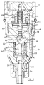
- a drilling 62 is provided in the second valve housing 48, the drilling 62 providing a communication path between the passage 46 and the supply line 60. As shown most clearly in Figure 2, the drilling 62 communicates with the through bore of the second valve housing 48, the drilling 62 being located such that the part of the through bore at the end face of the second valve housing 48 is of non-circular shape, the drilling 62 breaking into the through bore at the end face of the second valve housing.
- the stator 54 When injection is to be commenced, the stator 54 is energized to attract the armature 52 towards the stator against the action of a spring 68, the movement of the armature 52 resulting in movement of the valve member 50 to lift the end thereof away from the end face of the first valve housing 38 and to bring the enlarged region 50 a of the valve member 50 into engagement with its seating.
- Such movement of the valve member 50 breaks communication between the control chamber 44 and the delivery line 60 and instead permits communication between the control chamber 44 and the low pressure drain. The pressure within the control chamber 44 therefore falls.
- the stator 54 is de-energized thus the armature 52 and valve member 50 return under the action of the spring 68 to the position shown in Figures 1 and 2.
- the control chamber 44 no longer communicates with the low pressure drain and instead communicates with the supply passage 60.
- the fuel pressure within the control chamber 44 therefore increases, and a point will be reached at which the fuel pressure within the control chamber 44 is sufficient to return the valve needle 34 towards its seating thus terminating injection.
- the valve 20 is de-energized thus the valve member 26 thereof moves under the action of the spring 30 to a position in which fuel from the bore 12 is able to flow through the valve 20 to the low pressure drain 22.
- the fuel pressure within the bore 12 therefore falls.
Abstract
Description
Claims (10)
- An injector arrangement comprising a pump including a bore (12) within which a pumping plunger (14) is reciprocable, and an injector including a pressure control valve (20) arranged to control communication between the bore (12) and a low pressure reservoir (22), an injector needle (34) engageable with a seating, the needle (34) being resiliently biased into engagement with the seating, a control chamber (44) arranged such that the application of high pressure fuel thereto urges the needle (34) towards its seating, a needle control valve (50) arranged to control communication between the bore (12) and the control chamber (44) and between the control chamber (44) and a low pressure drain (22), and individual actuator arrangements (24, 52, 54) for actuating the pressure control valve (20) and needle control valve (50) independently of one another, wherein the needle control valve (50) comprises a valve member (50) slidable within a bore, an end of the valve member (50) being sealingly engageable with a surface extending in a plane normal to the axis of the valve member (50) to close a port (64) communicating with the low pressure drain (22).
- An injector arrangement as claimed in Claim 1, wherein the port (64) which communicates with the low pressure drain (22) is located generally coaxially with the valve member (50).
- An injector arrangement as claimed in Claim 1 or Claim 2, wherein a part (50a) of the valve member (50) spaced from the end thereof is engageable with a seating to control communication between the bore (12) and the control chamber (44).
- An injector arrangement as claimed in any one of the preceding claims, further comprising an abutment member (42a) having a surface exposed to the fuel pressure within the control chamber (44), the abutment member (42a) transmitting the force due to the action of the fuel pressure within the control chamber (44) to the valve needle (34).
- An injector arrangement as claimed in Claim 4, further comprising a spring (40) resiliently biassing the needle (34) towards its seating, the spring (40) engaging a spring abutment (42) moveable with the abutment member (42a).
- An injector arrangement as claimed in Claim 5, wherein the spring abutment (42) is integral with the abutment member (42a).
- An injector as claimed in Claim 5, wherein the abutment member (42a) engages the spring abutment (42), the force due to the fuel pressure within the control chamber (44) being transmitted to the valve needle (34) through the spring abutment (42).
- An injector arrangement as claimed in Claim 5, wherein the spring abutment (42b) is carried by the abutment member (42).
- An injector arrangement as claimed in any one of the preceding claims, wherein the injector is mounted upon the pump.
- An injector arrangement as claimed in any one of Claims 1 to 8, wherein the pump and the injector are spaced apart from one another, a pipe connecting the bore of the pump to the injector.
Applications Claiming Priority (2)
| Application Number | Priority Date | Filing Date | Title |
|---|---|---|---|
| GBGB9622335.9A GB9622335D0 (en) | 1996-10-26 | 1996-10-26 | Injector arrangement |
| GB9622335 | 1996-10-26 |
Publications (2)
| Publication Number | Publication Date |
|---|---|
| EP0840003A1 true EP0840003A1 (en) | 1998-05-06 |
| EP0840003B1 EP0840003B1 (en) | 2003-01-08 |
Family
ID=10802009
Family Applications (1)
| Application Number | Title | Priority Date | Filing Date |
|---|---|---|---|
| EP97308457A Expired - Lifetime EP0840003B1 (en) | 1996-10-26 | 1997-10-23 | Fuel injection arrangement |
Country Status (6)
| Country | Link |
|---|---|
| US (1) | US5915623A (en) |
| EP (1) | EP0840003B1 (en) |
| JP (1) | JP4068195B2 (en) |
| DE (1) | DE69718275T2 (en) |
| ES (1) | ES2189927T3 (en) |
| GB (1) | GB9622335D0 (en) |
Cited By (11)
| Publication number | Priority date | Publication date | Assignee | Title |
|---|---|---|---|---|
| GB2336628A (en) * | 1998-04-24 | 1999-10-27 | Lucas Ind Plc | A fuel injector, for an I.C. engine, having a three way two position needle control valve |
| EP1065368A2 (en) | 1999-06-30 | 2001-01-03 | Delphi Technologies, Inc. | Fuel injector |
| EP1120563A2 (en) * | 2000-01-27 | 2001-08-01 | Delphi Technologies, Inc. | Fuel injector |
| WO2002088542A1 (en) * | 2001-04-27 | 2002-11-07 | Robert Bosch Gmbh | Fuel injector comprising a sequential construction |
| EP1283355A1 (en) | 2001-08-07 | 2003-02-12 | Delphi Technologies, Inc. | Fuel injector |
| EP1335128A2 (en) * | 2002-02-08 | 2003-08-13 | Robert Bosch Gmbh | High pressure hydraulic valve, in particularly for an internal combustion engine fuel injection apparatus |
| EP1316717A3 (en) * | 2001-11-30 | 2003-11-26 | Robert Bosch Gmbh | Fuel injection system for internal combustion engine |
| WO2004074674A1 (en) | 1999-10-09 | 2004-09-02 | Paul Buckley | Fuel injector |
| US6807947B2 (en) | 2002-03-21 | 2004-10-26 | Robert Bosch Gmbh | Method and device for controlling fuel metering into an internal combustion engine |
| WO2005040598A1 (en) * | 2003-09-26 | 2005-05-06 | Robert Bosch Gmbh | Valve for controlling a connection in a high-pressure liquid system, particularly a fuel injection device for an internal combustion engine |
| DE10212509B4 (en) * | 2002-03-21 | 2013-03-21 | Robert Bosch Gmbh | Method and device for controlling fuel metering in an internal combustion engine |
Families Citing this family (15)
| Publication number | Priority date | Publication date | Assignee | Title |
|---|---|---|---|---|
| GB9820033D0 (en) * | 1998-09-16 | 1998-11-04 | Lucas Ind Plc | Fuel injector |
| DE19936667A1 (en) * | 1999-08-04 | 2001-02-22 | Bosch Gmbh Robert | Common rail injector |
| DE19937713C1 (en) * | 1999-08-10 | 2001-03-15 | Siemens Ag | Control valve arrangement for use in a fuel injector for internal combustion engines |
| DE19949527A1 (en) * | 1999-10-14 | 2001-04-19 | Bosch Gmbh Robert | Injector for a fuel injection system for internal combustion engines with a nozzle needle protruding into the valve control chamber |
| GB0107575D0 (en) * | 2001-03-27 | 2001-05-16 | Delphi Tech Inc | Control valve arrangement |
| US6439202B1 (en) | 2001-11-08 | 2002-08-27 | Cummins Inc. | Hybrid electronically controlled unit injector fuel system |
| GB0215490D0 (en) * | 2002-07-04 | 2002-08-14 | Delphi Tech Inc | Control valve arrangement |
| US7455243B2 (en) * | 2004-03-03 | 2008-11-25 | Caterpillar Inc. | Electronic unit injector with pressure assisted needle control |
| DE102005004069A1 (en) * | 2005-01-28 | 2006-08-03 | Volkswagen Mechatronic Gmbh & Co. Kg | Injection device e.g. pump-nozzle-injection device, for e.g. diesel engine, has sealing arrangement with O-rings to effect sealing of interface, which includes sealing surface with grooves to accommodate O-rings, at cavity or channel |
| US7547000B2 (en) * | 2005-03-08 | 2009-06-16 | Caterpillar Inc. | Valve coupling system |
| US7255091B2 (en) * | 2005-05-31 | 2007-08-14 | Caterpillar, Inc. | Fuel injector control system and method |
| US7111613B1 (en) | 2005-05-31 | 2006-09-26 | Caterpillar Inc. | Fuel injector control system and method |
| US7111614B1 (en) | 2005-08-29 | 2006-09-26 | Caterpillar Inc. | Single fluid injector with rate shaping capability |
| US7520266B2 (en) * | 2006-05-31 | 2009-04-21 | Caterpillar Inc. | Fuel injector control system and method |
| DE102006061896A1 (en) | 2006-12-28 | 2008-07-03 | Robert Bosch Gmbh | Fuel injector for internal combustion engine, has fluid channels extending between valve device and chamber, where one fluid channel is provided for application of pressure and other channel for discharge of pressure of control chamber |
Citations (5)
| Publication number | Priority date | Publication date | Assignee | Title |
|---|---|---|---|---|
| EP0240353A2 (en) * | 1986-04-04 | 1987-10-07 | Nippondenso Co., Ltd. | A fuel injection control device |
| EP0459429A1 (en) * | 1990-05-29 | 1991-12-04 | Toyota Jidosha Kabushiki Kaisha | Fuel injector |
| EP0647780A2 (en) * | 1993-10-08 | 1995-04-12 | Lucas Industries Public Limited Company | Fuel injection nozzle |
| GB2298025A (en) * | 1995-01-20 | 1996-08-21 | Caterpillar Inc | Axial force indentation or protrusion |
| EP0740068A2 (en) * | 1995-04-28 | 1996-10-30 | Lucas Industries public limited company | Fuel injection nozzle |
Family Cites Families (7)
| Publication number | Priority date | Publication date | Assignee | Title |
|---|---|---|---|---|
| CH669822A5 (en) * | 1986-02-12 | 1989-04-14 | Sulzer Ag | |
| JPH07109181B2 (en) * | 1986-12-05 | 1995-11-22 | 日本電装株式会社 | Fuel injection device for internal combustion engine |
| JPH0196466A (en) * | 1987-10-07 | 1989-04-14 | Honda Motor Co Ltd | Fuel injection nozzle for internal combustion engine |
| DE68922871T2 (en) * | 1988-03-04 | 1995-10-19 | Yamaha Motor Co Ltd | Fuel injector. |
| DE3937917A1 (en) * | 1989-11-15 | 1991-05-16 | Man Nutzfahrzeuge Ag | METHOD FOR INTERMITTENTLY INJECTING FUEL INTO THE COMBUSTION CHAMBER OF AN INTERNAL COMBUSTION ENGINE, AND DEVICE FOR CARRYING OUT THIS METHOD |
| DE4115477C2 (en) * | 1990-05-17 | 2003-02-06 | Avl Verbrennungskraft Messtech | Injection nozzle for an internal combustion engine |
| DE4336108C1 (en) * | 1993-10-22 | 1994-12-01 | Daimler Benz Ag | Solenoid valve on a fuel injection nozzle provided for internal combustion engines |
-
1996
- 1996-10-26 GB GBGB9622335.9A patent/GB9622335D0/en active Pending
-
1997
- 1997-10-22 US US08/955,676 patent/US5915623A/en not_active Expired - Lifetime
- 1997-10-23 ES ES97308457T patent/ES2189927T3/en not_active Expired - Lifetime
- 1997-10-23 DE DE69718275T patent/DE69718275T2/en not_active Expired - Lifetime
- 1997-10-23 EP EP97308457A patent/EP0840003B1/en not_active Expired - Lifetime
- 1997-10-27 JP JP29431397A patent/JP4068195B2/en not_active Expired - Lifetime
Patent Citations (5)
| Publication number | Priority date | Publication date | Assignee | Title |
|---|---|---|---|---|
| EP0240353A2 (en) * | 1986-04-04 | 1987-10-07 | Nippondenso Co., Ltd. | A fuel injection control device |
| EP0459429A1 (en) * | 1990-05-29 | 1991-12-04 | Toyota Jidosha Kabushiki Kaisha | Fuel injector |
| EP0647780A2 (en) * | 1993-10-08 | 1995-04-12 | Lucas Industries Public Limited Company | Fuel injection nozzle |
| GB2298025A (en) * | 1995-01-20 | 1996-08-21 | Caterpillar Inc | Axial force indentation or protrusion |
| EP0740068A2 (en) * | 1995-04-28 | 1996-10-30 | Lucas Industries public limited company | Fuel injection nozzle |
Cited By (16)
| Publication number | Priority date | Publication date | Assignee | Title |
|---|---|---|---|---|
| GB2336628A (en) * | 1998-04-24 | 1999-10-27 | Lucas Ind Plc | A fuel injector, for an I.C. engine, having a three way two position needle control valve |
| EP1065368A2 (en) | 1999-06-30 | 2001-01-03 | Delphi Technologies, Inc. | Fuel injector |
| EP1065368A3 (en) * | 1999-06-30 | 2002-07-31 | Delphi Technologies, Inc. | Fuel injector |
| WO2004074674A1 (en) | 1999-10-09 | 2004-09-02 | Paul Buckley | Fuel injector |
| EP1120563A2 (en) * | 2000-01-27 | 2001-08-01 | Delphi Technologies, Inc. | Fuel injector |
| EP1120563A3 (en) * | 2000-01-27 | 2003-08-13 | Delphi Technologies, Inc. | Fuel injector |
| WO2002088542A1 (en) * | 2001-04-27 | 2002-11-07 | Robert Bosch Gmbh | Fuel injector comprising a sequential construction |
| EP1283355A1 (en) | 2001-08-07 | 2003-02-12 | Delphi Technologies, Inc. | Fuel injector |
| EP1316717A3 (en) * | 2001-11-30 | 2003-11-26 | Robert Bosch Gmbh | Fuel injection system for internal combustion engine |
| US6808124B2 (en) | 2001-11-30 | 2004-10-26 | Robert Bosch Gmbh | Fuel injection system for an internal combustion engine |
| EP1335128A2 (en) * | 2002-02-08 | 2003-08-13 | Robert Bosch Gmbh | High pressure hydraulic valve, in particularly for an internal combustion engine fuel injection apparatus |
| EP1335128A3 (en) * | 2002-02-08 | 2004-10-20 | Robert Bosch Gmbh | High pressure hydraulic valve, in particularly for an internal combustion engine fuel injection apparatus |
| US6807947B2 (en) | 2002-03-21 | 2004-10-26 | Robert Bosch Gmbh | Method and device for controlling fuel metering into an internal combustion engine |
| DE10212509B4 (en) * | 2002-03-21 | 2013-03-21 | Robert Bosch Gmbh | Method and device for controlling fuel metering in an internal combustion engine |
| WO2005040598A1 (en) * | 2003-09-26 | 2005-05-06 | Robert Bosch Gmbh | Valve for controlling a connection in a high-pressure liquid system, particularly a fuel injection device for an internal combustion engine |
| US7513441B2 (en) | 2003-09-26 | 2009-04-07 | Robert Bosch Gmbh | Valve for controlling a connection in a high-pressure fuel injection apparatus for an internal combustion engine |
Also Published As
| Publication number | Publication date |
|---|---|
| ES2189927T3 (en) | 2003-07-16 |
| EP0840003B1 (en) | 2003-01-08 |
| DE69718275T2 (en) | 2003-10-02 |
| DE69718275D1 (en) | 2003-02-13 |
| US5915623A (en) | 1999-06-29 |
| GB9622335D0 (en) | 1996-12-18 |
| JP4068195B2 (en) | 2008-03-26 |
| JPH10148167A (en) | 1998-06-02 |
Similar Documents
| Publication | Publication Date | Title |
|---|---|---|
| EP0840003B1 (en) | Fuel injection arrangement | |
| EP0889230B1 (en) | Fuel injector | |
| EP0823550B1 (en) | Injector | |
| US6267306B1 (en) | Fuel injector including valve needle, injection control valve, and drain valve | |
| EP0823549B1 (en) | Injector | |
| EP0878623B1 (en) | Fuel injector | |
| US6651625B1 (en) | Fuel system and pump suitable for use therein | |
| EP0726390A1 (en) | Fuel system | |
| JPS6172869A (en) | Electrically controlled pump nozzle for injecting fuel for diesel internal combustion engine | |
| EP0333096A2 (en) | Improved valve support for accumulator type fuel injection nozzle | |
| EP0372714A1 (en) | Fuel injection nozzle | |
| EP1651863B1 (en) | Common rail fuel pump | |
| US6502555B1 (en) | Fuel injector | |
| US6405940B2 (en) | Fuel injector | |
| EP0987430B1 (en) | Fuel injector | |
| EP1136692B1 (en) | Fuel injector with a control rod controlled by the fuel pressure in a control chamber | |
| EP0736687B1 (en) | Fuel pumping apparatus | |
| EP0853196A1 (en) | Injector | |
| EP0965750B1 (en) | Fuel injector | |
| EP1065368A2 (en) | Fuel injector | |
| JP2002523671A (en) | Control unit for controlling the pressure buildup in the pump unit | |
| JPH0429082Y2 (en) | ||
| EP1283355B1 (en) | Fuel injector | |
| GB2345741A (en) | Pressure balanced control valve |
Legal Events
| Date | Code | Title | Description |
|---|---|---|---|
| PUAI | Public reference made under article 153(3) epc to a published international application that has entered the european phase |
Free format text: ORIGINAL CODE: 0009012 |
|
| AK | Designated contracting states |
Kind code of ref document: A1 Designated state(s): DE ES FR GB IT |
|
| AX | Request for extension of the european patent |
Free format text: AL;LT;LV;RO;SI |
|
| 17P | Request for examination filed |
Effective date: 19981105 |
|
| AKX | Designation fees paid |
Free format text: DE ES FR GB IT |
|
| RBV | Designated contracting states (corrected) |
Designated state(s): DE ES FR GB IT |
|
| RAP1 | Party data changed (applicant data changed or rights of an application transferred) |
Owner name: CATERPILLAR INC. Owner name: LUCAS INDUSTRIES LIMITED |
|
| RAP1 | Party data changed (applicant data changed or rights of an application transferred) |
Owner name: CATERPILLAR INC. Owner name: DELPHI TECHNOLOGIES, INC. |
|
| 17Q | First examination report despatched |
Effective date: 20010212 |
|
| GRAG | Despatch of communication of intention to grant |
Free format text: ORIGINAL CODE: EPIDOS AGRA |
|
| GRAG | Despatch of communication of intention to grant |
Free format text: ORIGINAL CODE: EPIDOS AGRA |
|
| GRAG | Despatch of communication of intention to grant |
Free format text: ORIGINAL CODE: EPIDOS AGRA |
|
| GRAH | Despatch of communication of intention to grant a patent |
Free format text: ORIGINAL CODE: EPIDOS IGRA |
|
| GRAH | Despatch of communication of intention to grant a patent |
Free format text: ORIGINAL CODE: EPIDOS IGRA |
|
| GRAA | (expected) grant |
Free format text: ORIGINAL CODE: 0009210 |
|
| AK | Designated contracting states |
Kind code of ref document: B1 Designated state(s): DE ES FR GB IT |
|
| REG | Reference to a national code |
Ref country code: GB Ref legal event code: FG4D |
|
| REF | Corresponds to: |
Ref document number: 69718275 Country of ref document: DE Date of ref document: 20030213 Kind code of ref document: P |
|
| ET | Fr: translation filed | ||
| REG | Reference to a national code |
Ref country code: ES Ref legal event code: FG2A Ref document number: 2189927 Country of ref document: ES Kind code of ref document: T3 |
|
| PGFP | Annual fee paid to national office [announced via postgrant information from national office to epo] |
Ref country code: GB Payment date: 20031006 Year of fee payment: 7 |
|
| PGFP | Annual fee paid to national office [announced via postgrant information from national office to epo] |
Ref country code: ES Payment date: 20031020 Year of fee payment: 7 |
|
| PLBE | No opposition filed within time limit |
Free format text: ORIGINAL CODE: 0009261 |
|
| STAA | Information on the status of an ep patent application or granted ep patent |
Free format text: STATUS: NO OPPOSITION FILED WITHIN TIME LIMIT |
|
| 26N | No opposition filed |
Effective date: 20031009 |
|
| PG25 | Lapsed in a contracting state [announced via postgrant information from national office to epo] |
Ref country code: GB Free format text: LAPSE BECAUSE OF NON-PAYMENT OF DUE FEES Effective date: 20041023 |
|
| PG25 | Lapsed in a contracting state [announced via postgrant information from national office to epo] |
Ref country code: ES Free format text: LAPSE BECAUSE OF NON-PAYMENT OF DUE FEES Effective date: 20041025 |
|
| GBPC | Gb: european patent ceased through non-payment of renewal fee |
Effective date: 20041023 |
|
| PG25 | Lapsed in a contracting state [announced via postgrant information from national office to epo] |
Ref country code: IT Free format text: LAPSE BECAUSE OF NON-PAYMENT OF DUE FEES Effective date: 20051023 |
|
| REG | Reference to a national code |
Ref country code: ES Ref legal event code: FD2A Effective date: 20041025 |
|
| REG | Reference to a national code |
Ref country code: FR Ref legal event code: TQ Owner name: DELPHI TECHNOLOGIES HOLDING S.A.R.L., LU Effective date: 20111020 |
|
| REG | Reference to a national code |
Ref country code: DE Ref legal event code: R082 Ref document number: 69718275 Country of ref document: DE Representative=s name: LEONHARD & PARTNER PATENTANWAELTE, DE |
|
| REG | Reference to a national code |
Ref country code: DE Ref legal event code: R082 Ref document number: 69718275 Country of ref document: DE Representative=s name: LEONHARD & PARTNER PATENTANWAELTE, DE Effective date: 20140701 Ref country code: DE Ref legal event code: R081 Ref document number: 69718275 Country of ref document: DE Owner name: DELPHI INTERNATIONAL OPERATIONS LUXEMBOURG S.A, LU Free format text: FORMER OWNERS: CATERPILLAR INC., PEORIA, ILL., US; DELPHI TECHNOLOGIES HOLDING S.A.R.L., BASCHARAGE, LU Effective date: 20140701 Ref country code: DE Ref legal event code: R081 Ref document number: 69718275 Country of ref document: DE Owner name: CATERPILLAR INC., PEORIA, US Free format text: FORMER OWNERS: CATERPILLAR INC., PEORIA, ILL., US; DELPHI TECHNOLOGIES HOLDING S.A.R.L., BASCHARAGE, LU Effective date: 20140701 Ref country code: DE Ref legal event code: R081 Ref document number: 69718275 Country of ref document: DE Owner name: DELPHI INTERNATIONAL OPERATIONS LUXEMBOURG S.A, LU Free format text: FORMER OWNER: CATERPILLAR INC., DELPHI TECHNOLOGIES HOLDING S.A, , LU Effective date: 20140701 Ref country code: DE Ref legal event code: R081 Ref document number: 69718275 Country of ref document: DE Owner name: CATERPILLAR INC., PEORIA, US Free format text: FORMER OWNER: CATERPILLAR INC., DELPHI TECHNOLOGIES HOLDING S.A, , LU Effective date: 20140701 |
|
| REG | Reference to a national code |
Ref country code: FR Ref legal event code: TQ Owner name: DELPHI INTERNATIONAL OPERATIONS LUXEMBOURG S.A, LU Effective date: 20140826 Ref country code: FR Ref legal event code: TQ Owner name: CATERPILLAR INC., US Effective date: 20140826 |
|
| REG | Reference to a national code |
Ref country code: FR Ref legal event code: PLFP Year of fee payment: 19 |
|
| REG | Reference to a national code |
Ref country code: FR Ref legal event code: PLFP Year of fee payment: 20 |
|
| PGFP | Annual fee paid to national office [announced via postgrant information from national office to epo] |
Ref country code: FR Payment date: 20161025 Year of fee payment: 20 Ref country code: DE Payment date: 20161027 Year of fee payment: 20 |
|
| REG | Reference to a national code |
Ref country code: DE Ref legal event code: R071 Ref document number: 69718275 Country of ref document: DE |