EP1065065A2 - Apparatus and method of stencil making - Google Patents
Apparatus and method of stencil making Download PDFInfo
- Publication number
- EP1065065A2 EP1065065A2 EP00305479A EP00305479A EP1065065A2 EP 1065065 A2 EP1065065 A2 EP 1065065A2 EP 00305479 A EP00305479 A EP 00305479A EP 00305479 A EP00305479 A EP 00305479A EP 1065065 A2 EP1065065 A2 EP 1065065A2
- Authority
- EP
- European Patent Office
- Prior art keywords
- print head
- thermal print
- heat generating
- line
- main scanning
- Prior art date
- Legal status (The legal status is an assumption and is not a legal conclusion. Google has not performed a legal analysis and makes no representation as to the accuracy of the status listed.)
- Withdrawn
Links
Images



Classifications
-
- B—PERFORMING OPERATIONS; TRANSPORTING
- B41—PRINTING; LINING MACHINES; TYPEWRITERS; STAMPS
- B41J—TYPEWRITERS; SELECTIVE PRINTING MECHANISMS, i.e. MECHANISMS PRINTING OTHERWISE THAN FROM A FORME; CORRECTION OF TYPOGRAPHICAL ERRORS
- B41J2/00—Typewriters or selective printing mechanisms characterised by the printing or marking process for which they are designed
- B41J2/315—Typewriters or selective printing mechanisms characterised by the printing or marking process for which they are designed characterised by selective application of heat to a heat sensitive printing or impression-transfer material
- B41J2/32—Typewriters or selective printing mechanisms characterised by the printing or marking process for which they are designed characterised by selective application of heat to a heat sensitive printing or impression-transfer material using thermal heads
- B41J2/35—Typewriters or selective printing mechanisms characterised by the printing or marking process for which they are designed characterised by selective application of heat to a heat sensitive printing or impression-transfer material using thermal heads providing current or voltage to the thermal head
- B41J2/355—Control circuits for heating-element selection
-
- B—PERFORMING OPERATIONS; TRANSPORTING
- B41—PRINTING; LINING MACHINES; TYPEWRITERS; STAMPS
- B41J—TYPEWRITERS; SELECTIVE PRINTING MECHANISMS, i.e. MECHANISMS PRINTING OTHERWISE THAN FROM A FORME; CORRECTION OF TYPOGRAPHICAL ERRORS
- B41J2202/00—Embodiments of or processes related to ink-jet or thermal heads
- B41J2202/30—Embodiments of or processes related to thermal heads
- B41J2202/32—Thermal head for perforating stencil
Definitions
- the present invention relates to a stencil making apparatus for thermo-sensitively perforating stencil sheet, particularly to an apparatus and a method of stencil making capable of restraining occurrence of moire on stencil sheet as perforated.
- a stencil making apparatus for perforating stencil sheet used in printing perforates stencil sheet by applying heat thereto.
- the perforated stencil sheet is transferred to a printing section and image is formed on print sheet by projectedly supplying ink from the perforation.
- the stencil sheet is grossly classified into two kinds, that is, 1) one constituted by film and gauze (supporter having mesh structure) and 2) one comprising film and Japanese paper. Particularly, the stencil sheet of 1) is frequently used in a simplified type stencil printer.
- the stencil making apparatus is provided with a thermal print head and a platen and stencil sheet is thermal-sensitively perforated by the thermal print head while feeding the stencil sheet in a direction orthogonal to the thermal print head by rotating the platen.
- main scanning is carried out in the width direction of the stencil sheet by the thermal print head and sub-scan is carried out in the length direction of the stencil sheet by rotating the platen.
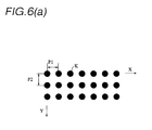
- Figs. 6(a) and 6(b) are drawings showing a perforated state of stencil sheet.
- supporters ST of the stencil sheet S are formed in a mesh-like shape and vertically and horizontally arranged regularly at a predetermined pitch P3 in directions the same as the directions of arranging the perforations K (main scanning direction X and sub scan direction Y).
- the respective pitches establish a relationship of 3:2, a predetermined regularity is produced therebetween and accordingly, there occurs moire which is easily recognizable by optical observation.
- a direction of arranging mesh of supporters and a main scanning direction of a thermal print head are inclined relative to each other such that the directions are not orthogonal to each other.
- the thermal print head must be attached to be inclined to a transfer direction of stencil sheet and therefore, structure of a stencil machine becomes complicated and the transfer becomes unstable.
- the present invention has been carried out in order to resolve the above-described problem and it is an object of the present invention to provide an apparatus and a method of stencil making capable of diminishing occurrence of moire by perforating stencil sheet having supporters in an arrangement having a regularity.
- a stencil making apparatus for thermal-sensitively perforating stencil sheet by a thermal print head, the stencil making apparatus comprising controlling means for driving contiguous N pieces of heat generating elements of the thermal print head while shifting heat generating timings at every 1/N of a period of one line of main scanning in perforating inputted image data of the one line of the main scanning.
- a stencil making apparatus for perforating stencil sheet having supporters in a mesh structure having a regular pitch
- the stencil making apparatus comprising a thermal print head arranged with a plurality of pieces of heat generating members at a regular pitch and controlling means for dividing inputted image data of one line of main scanning such that contiguous N pieces of the heat generating elements of the thermal print head generate different lines of print data of N lines divided into 1/N of the period of the one line and outputting the N lines of the print data to the thermal print head at different timings.
- the controlling means outputs the N lines of the print data to the thermal print head during a time period of the period of the one line of the main scanning.
- a constitution further comprising setting means for setting a value of N (at least, N is equal to or larger than 2) such that a regularity is diminished in a relationship between a pitch of supporters of the stencil sheet and a pitch of the heat generating members of the thermal print head, wherein the controlling means controls to divide the print data of the N lines based on the value of N set by the setting means and output timings thereof.
- a stencil making method of thermal-sensitively perforating stencil sheet by a thermal print head wherein in perforating inputted image data of one line of main scanning, contiguous N pieces of heat generating elements of the thermal print head are driven while respectively shifting heat generating timings at every 1/N of a period of the one line of the main scanning.
- contiguous heat generating members do not generate heat simultaneously but generate heat at timings different from each other and accordingly, an angle may be constituted between the stencil sheet and a main scanning direction of the thermal print head.
- the stencil sheet S used in the present invention is constituted by the film and the gauze (supporters having mesh structure) shown by Figs. 6(a) and 6(b). Further, the supporters are provided with regularity at the predetermined pitch P3 in directions respectively orthogonal to the width and the length directions of the stencil sheet S.
- Fig. 1 is a block diagram showing constitution of a first embodiment of a stencil making apparatus according to the present invention and Fig. 2 is a side view showing structure of the stencil making apparatus.
- Controlling means 1 is constituted by a processor such as CPU and storage sections such as ROM, RAM and the like.
- the controlling means 1 is inputted with image data for stencil making from outside.
- the controlling means 1 divides inputted image data of one line of the thermal print head by N and outputs print data to a thermal print head 5 in N times.
- the notation N designates a number of selecting a plurality of heat generating members H which are contiguous to each other in the thermal print head 5.
- Setting means 3 is set with the number of N divisions.
- the storage sections of the controlling means 1 may be used for the setting means 3.
- the thermal print head (TPH) 5 is constituted by linearly arranging the plurality of head generating members H (H -1 through H -N ; N is a natural number equal to or larger than 1) at the predetermined pitch P1.
- the respective heat generating members H are arranged in the depth direction of drawing in Fig. 2. Portions of the stencil sheet S in correspondence with the heated heating members H, are perforated by heat.
- the controlling means 1 transfers stencil sheet S in the length direction by rotating the platen roller 6 in the perforating operation.
- the heat generating members H in correspondence with image data in the length direction of the thermal print head 5, generate heat and the perforating operation is carried out by main scanning of 1 line. Thereafter, after carrying out sub scan of rotating the platen roller 6 by a predetermined amount, the perforating operation is carried out by main scanning of a second line spaced part from the above-described line by the predetermined pitch P2. Thereafter, by main scanning of a plurality of lines, stencil image in correspondence with image data is perforated on the stencil sheet S.
- the controlling means 1 is provided with data dividing means 1a for dividing the inputted image data into N divisions by a procedure, mentioned later and data outputting means 1b for outputting print data which has been divided into N divisions by the data dividing means 1a at respective predetermined timings. These means are operated based on time information of a timer 2.
- the rotational speed of the platen roller 6 (speed of sub scan) stays constant and the data outputting means 1b divides a time period of the pitch P2 of sub scan (corresponding to a period of main scanning of 1 line) equally by N and transmits respective print data to the thermal print head 5 by N times.
- Fig. 3 illustrates timing charts showing print data outputted from the controlling means 1.
- the abscissa designates time axis in the main scanning direction X and the ordinate designates a time axis of the sub scan direction Y.
- Fig. 3(a) shows image data inputted to the controlling means 1 and in the illustrated example, for convenience, it is assumed that the image data is constituted only by data for making the respective heat generating members H of the thermal print head 5 generate heat. Perforated image of one line is formed in the main scanning direction X by print data 1 through 3, although a description thereof will be given later. Further, the image data is constituted only by the data for making the respective heat generating members 1 generate heat to thereby thermal-sensitively perforate the line in a linear shape.
- the data outputting means 1b controls a period of transmitting a total of 3 lines of print data.
- print data 2 of a second line successive to image data (a+1) of a second pixel of the inputted image data, there is transmitted image data (a+N+1) of a fourth pixel spaced apart from the image data (a+1) by an interval of two pixels of image data.
- print data 3 of a third line successive to image data (a+2) of a third pixel of the inputted image data, there is transmitted image data (a+N+2) of a fifth pixel spaced apart from the image data (a+2) by an interval of two pixels of image data.
- the length of data of a total of one line corresponds to a number of the heat generating members H provided to the thermal print head 5 and the processing is carried out such that the length of previously inputted image data is adapted thereto.
- the image data 1 through 3 of the three lines are constituted by dividing a moving time period of the pitch P2 of sub scan by N and accordingly, during a time period of sub scan of 1 line, the thermal print head 5 transmits the print data 1 through 3 by 3 times on the same main scanning line.
- Fig. 4 is a drawing showing a state of forming respective perforations perforated by the thermal print head 5 based on print data of the controlling means 1.
- a state of forming perforations K of 3 lines in correspondence with 3 image data. Further, for convenience, display of the perforations K is changed at every arrangements of respective lines of the perforations K in the drawing.
- the respective perforations K are formed respectively by the pitch P1 of arranging the heat generating members H.
- an interval between a first line and a fourth line constitutes the pitch P2 in the sub scan direction and the respective perforations K are formed by dividing the pitch P2 in 3.
- the respective perforations K are perforated in a state in which the respective perforations K are arranged not in straight lines but obliquely in a range of set N relative to either of the main scanning direction and the sub scan direction.
- the mesh of the supporters ST of the stencil sheet S is the predetermined pitch P3 (for example, 200 dpi) along the main scanning direction and the sub scan direction
- the regularity between the pitch P3 of the mesh and the pitches P1 and P2 of the respective perforations K can be diminished. Therefore, occurrence of moire can be diminished.
- the perforations K are perforated obliquely by a unit of set N pieces and therefore, viewing very finely, the line in a linear shape indicated by the image data is formed obliquely by the unit of N pieces.
- respective points of 1) point in which a number of perforations on 1 line of main scanning is set to be large in accordance with the number of the heat generating members (H -1 through H -N ) of the thermal print head 5 2) point in which oblique perforation is carried out within a range of 1 line of sub scan and 3) point in which oozing of ink is caused in printing operation after the stencil making operation, an influence by oblique perforation on image formed on print paper is to an unrecognizable degree.
- the perforations K are formed always accompanied by a time difference among contiguous ones of the heat generating members H and therefore, the contiguous ones of the perforations K are not jointed and the respective perforations K can be perforated independently from each other.
- thermal history control of the thermal print head 5 can be dispensed with. According to the thermal print head 5, thermal energy applied to the heat generating members H tends to accumulate and accordingly, there is generally carried out thermal history control for controlling thermal energy of the heat generating members H at current time based on past heat generation history of contiguous ones of the plurality of heat generating members H (refer to Japanese Patent Laid-Open No. 8065/1990 and the like).
- a number of the heat generating members H simultaneously generating heat in the thermal print head 5 becomes 1/N thereof. Therefore, peak current supplied to the thermal print head 5 can be restrained to 1/N of the conventional case at maximum. Thereby, small capacity formation of power supply and reduction of wiring capacity can be achieved.
- a number of selecting contiguous ones of the heat generating members H (number of dividing data) is set to 3
- the present invention is not limited thereto but effect of diminishing moire can be achieved so far as N is equal to or larger than 2.
- the number of N may be set to a desired value capable of diminishing the regularity of the relationship between the resolution of the thermal print head 5 (pitch P1 of heat generating member H) and the mesh pitch P3 of the supporters of the stencil sheet S.
- the pitch P1 of main scanning and the pitch P2 of sub scan are the same as each other, it is not necessary that the pitches P1 and P2 are the same. Further, the pitch P2 on the side of sub scan can be made variable arbitrarily.
- an angle of arrangement of the plurality of perforations K within a range of N is increased relative to the main scanning direction X and when the pitch P2 on the side of sub scan is narrowed, the angle of arrangement by the plurality of perforations K within the range of N can be reduced relative to the main scanning direction X.
- the pitch P2 may be set to a desired value capable of reducing the regularity of the relationship between the pitch P2 and the mesh pitch P3 of the supporters of the stencil sheet S.
- the thermal print head 5 is arranged with the respective heat generating members H (H -1 through H -N ) at the predetermined pitch P1 in compliance with the resolution.
- the respective heat generating members H -1 through H -N are connected to control lines 8 -1 through 8 -N such that contiguous ones of the heat generating members connected thereto are connected to different control lines.
- control lines 8 -1 through 8 -3 are used.
- the control line 8 -1 is connected with the heat generating members H -1 , H -4 , ...at every three pieces.
- the control line 8 -2 is connected with heat generating members H -2 , H -5 , ...at every three pieces.
- the control line H -3 is connected with the heat generating members H -3 , H -6 , ...at every three pieces.
- the thermal print head 5 is supplied with print data from the controlling means at respectively different timings via 3 pieces of the control lines 8 -1 through 8 -3 .
- N pieces of heat generating elements of a thermal print head are driven while shifting heat generation timings at every 1/N of a period of 1 line of main scanning and accordingly, when perforating inputted image data of 1 line of main scanning, N pieces of the heat generating members do not generate heat simultaneously but generate heat at different timings.
- perforations of stencil sheet can be perforated independently from each other. Further, thermal history control with regard to the thermal print head can be dispensed with.
- moire can be suppressed without changing the resolution of the thermal print head, the structure of the thermal print head per se and attaching structures thereof, further, while using stencil sheet constituted by supporters having a regularity in mesh pitch.
- the heat generating elements are divided into N divisions and are driven at timings respectively different from each other and accordingly, power supply for supplying power to the thermal print head and capacity of wirings can be reduced to 1/N thereof and the cost related to a power supply apparatus can be reduced.
Landscapes
- Manufacture Or Reproduction Of Printing Formes (AREA)
- Electronic Switches (AREA)
Abstract
Description
Claims (5)
- A stencil making apparatus for thermal-sensitively perforating stencil sheet by a thermal print head, said stencil making apparatus comprising:
controlling means for driving contiguous N pieces of heat generating elements of the thermal print head while shifting heat generating timings at every 1/N of a period of one line of main scanning in perforating inputted image data of the one line of the main scanning. - A stencil making apparatus for perforating stencil sheet having supporters in a mesh structure having a regular pitch, said stencil making apparatus comprising:a thermal print head arranged with a plurality of pieces of heat generating members at a regular pitch; andcontrolling means for dividing inputted image data of one line of main scanning such that contiguous N pieces of the heat generating elements of the thermal print head generate different lines of print data of N lines divided into 1/N of the period of the one line and outputting the N lines of the print data to the thermal print head at different timings.
- The stencil making apparatus according to Claim 2:
wherein the controlling means outputs the N lines of the print data to the thermal print head during a time period of the period of the one line of the main scanning. - The stencil making apparatus according to either of Claims 2 and 3, further comprising:setting means for setting a value of N (at least, N is equal to or larger than 2) such that a regularity is diminished in a relationship between a pitch of supporters of the stencil sheet and a pitch of the heat generating members of the thermal print head;wherein the controlling means controls to divide the print data of the N lines based on the value of N set by the setting means and output timings thereof.
- A stencil making method of thermal-sensitively perforating stencil sheet by a thermal print head:
wherein in perforating inputted image data of one line of main scanning, contiguous N pieces of heat generating elements of the thermal print head are driven while respectively shifting heat generating timings at every 1/N of a period of the one line of the main scanning.
Applications Claiming Priority (2)
| Application Number | Priority Date | Filing Date | Title |
|---|---|---|---|
| JP18369399 | 1999-06-29 | ||
| JP11183693A JP2001010015A (en) | 1999-06-29 | 1999-06-29 | Plate making apparatus and method |
Publications (2)
| Publication Number | Publication Date |
|---|---|
| EP1065065A2 true EP1065065A2 (en) | 2001-01-03 |
| EP1065065A3 EP1065065A3 (en) | 2001-03-21 |
Family
ID=16140299
Family Applications (1)
| Application Number | Title | Priority Date | Filing Date |
|---|---|---|---|
| EP00305479A Withdrawn EP1065065A3 (en) | 1999-06-29 | 2000-06-29 | Apparatus and method of stencil making |
Country Status (3)
| Country | Link |
|---|---|
| US (1) | US6540417B1 (en) |
| EP (1) | EP1065065A3 (en) |
| JP (1) | JP2001010015A (en) |
Families Citing this family (1)
| Publication number | Priority date | Publication date | Assignee | Title |
|---|---|---|---|---|
| JP2008296403A (en) * | 2007-05-29 | 2008-12-11 | Tohoku Ricoh Co Ltd | Heat-sensitive stencil printing equipment |
Family Cites Families (5)
| Publication number | Priority date | Publication date | Assignee | Title |
|---|---|---|---|---|
| JP2565212B2 (en) | 1989-07-14 | 1996-12-18 | ソニー株式会社 | Thermal printer |
| US5245932A (en) * | 1991-01-23 | 1993-09-21 | Riso Kagaku Corporation | Heat-sensitive stencil master sheet |
| JP2801982B2 (en) | 1991-08-21 | 1998-09-21 | 富士写真フイルム株式会社 | How to make a stencil |
| JP2998458B2 (en) * | 1992-09-24 | 2000-01-11 | ブラザー工業株式会社 | Plate making equipment |
| US5902053A (en) | 1995-10-11 | 1999-05-11 | Sony Corporation | Video printer having thermal head |
-
1999
- 1999-06-29 JP JP11183693A patent/JP2001010015A/en active Pending
-
2000
- 2000-06-26 US US09/604,058 patent/US6540417B1/en not_active Expired - Fee Related
- 2000-06-29 EP EP00305479A patent/EP1065065A3/en not_active Withdrawn
Also Published As
| Publication number | Publication date |
|---|---|
| EP1065065A3 (en) | 2001-03-21 |
| US6540417B1 (en) | 2003-04-01 |
| JP2001010015A (en) | 2001-01-16 |
Similar Documents
| Publication | Publication Date | Title |
|---|---|---|
| EP0827107B1 (en) | Matrix printing method and apparatus | |
| US6670976B2 (en) | Method of and apparatus for controlling thermal head | |
| US6443554B1 (en) | Printing device, printing method, and recording medium | |
| EP1149708B1 (en) | Non-uniform overlapping printing | |
| US6540417B1 (en) | Stencil making apparatus | |
| JP2998458B2 (en) | Plate making equipment | |
| JPS5955755A (en) | Printing control of color printer | |
| EP0901097A2 (en) | Method and apparatus for recording data on a recording medium | |
| JP2010201731A (en) | Image recorder, method of regulating driving phase in image recorder, and method of outputting position regulation chart in image recorder | |
| EP1053869B1 (en) | Method of and apparatus for making heat-sensitive stencil master | |
| JP3680909B2 (en) | Serial printer | |
| EP0931668A2 (en) | Recording method in ink jet printer | |
| JP3503533B2 (en) | Printing apparatus, printing method, and recording medium | |
| JPH11277791A (en) | Image forming apparatus | |
| JP2927092B2 (en) | Dot printing method | |
| EP1479522B1 (en) | Method and device for printing with a uniform printing medium transport distance | |
| JP3749014B2 (en) | Head data creation device and head data creation method | |
| JP2001030522A (en) | Color inkjet printer | |
| JPH05116355A (en) | Melting type thermal transfer recording method | |
| JPH07323609A (en) | Image forming apparatus and method | |
| JP2676147B2 (en) | Facsimile machine | |
| JP2010201732A (en) | Image recorder, method of regulating driving phase in image recorder, and method of outputting position regulation chart in image recorder | |
| JP2000318215A (en) | Interlaced printer and interlaced printing method | |
| JP2000043306A (en) | Printer apparatus | |
| JP2002120402A (en) | Interlaced printer and interlaced printing method |
Legal Events
| Date | Code | Title | Description |
|---|---|---|---|
| PUAI | Public reference made under article 153(3) epc to a published international application that has entered the european phase |
Free format text: ORIGINAL CODE: 0009012 |
|
| 17P | Request for examination filed |
Effective date: 20000711 |
|
| AK | Designated contracting states |
Kind code of ref document: A2 Designated state(s): DE FR GB |
|
| AX | Request for extension of the european patent |
Free format text: AL;LT;LV;MK;RO;SI |
|
| PUAL | Search report despatched |
Free format text: ORIGINAL CODE: 0009013 |
|
| AK | Designated contracting states |
Kind code of ref document: A3 Designated state(s): AT BE CH CY DE DK ES FI FR GB GR IE IT LI LU MC NL PT SE |
|
| AX | Request for extension of the european patent |
Free format text: AL;LT;LV;MK;RO;SI |
|
| RIC1 | Information provided on ipc code assigned before grant |
Free format text: 7B 41J 2/355 A, 7B 41C 1/14 B |
|
| AKX | Designation fees paid |
Free format text: DE FR GB |
|
| STAA | Information on the status of an ep patent application or granted ep patent |
Free format text: STATUS: THE APPLICATION IS DEEMED TO BE WITHDRAWN |
|
| 18D | Application deemed to be withdrawn |
Effective date: 20070103 |