EP1064881A2 - Multi-axis planar mechanism for a positioner patient platform - Google Patents
Multi-axis planar mechanism for a positioner patient platform Download PDFInfo
- Publication number
- EP1064881A2 EP1064881A2 EP00305465A EP00305465A EP1064881A2 EP 1064881 A2 EP1064881 A2 EP 1064881A2 EP 00305465 A EP00305465 A EP 00305465A EP 00305465 A EP00305465 A EP 00305465A EP 1064881 A2 EP1064881 A2 EP 1064881A2
- Authority
- EP
- European Patent Office
- Prior art keywords
- actuator drive
- patient
- patient table
- base
- actuator
- Prior art date
- Legal status (The legal status is an assumption and is not a legal conclusion. Google has not performed a legal analysis and makes no representation as to the accuracy of the status listed.)
- Withdrawn
Links
Images


Classifications
-
- A—HUMAN NECESSITIES
- A61—MEDICAL OR VETERINARY SCIENCE; HYGIENE
- A61B—DIAGNOSIS; SURGERY; IDENTIFICATION
- A61B6/00—Apparatus or devices for radiation diagnosis; Apparatus or devices for radiation diagnosis combined with radiation therapy equipment
- A61B6/04—Positioning of patients; Tiltable beds or the like
-
- A—HUMAN NECESSITIES
- A61—MEDICAL OR VETERINARY SCIENCE; HYGIENE
- A61B—DIAGNOSIS; SURGERY; IDENTIFICATION
- A61B5/00—Measuring for diagnostic purposes; Identification of persons
- A61B5/70—Means for positioning the patient in relation to the detecting, measuring or recording means
- A61B5/704—Tables
-
- A—HUMAN NECESSITIES
- A61—MEDICAL OR VETERINARY SCIENCE; HYGIENE
- A61G—TRANSPORT, PERSONAL CONVEYANCES, OR ACCOMMODATION SPECIALLY ADAPTED FOR PATIENTS OR DISABLED PERSONS; OPERATING TABLES OR CHAIRS; CHAIRS FOR DENTISTRY; FUNERAL DEVICES
- A61G13/00—Operating tables; Auxiliary appliances therefor
- A61G13/02—Adjustable operating tables; Controls therefor
-
- A—HUMAN NECESSITIES
- A61—MEDICAL OR VETERINARY SCIENCE; HYGIENE
- A61G—TRANSPORT, PERSONAL CONVEYANCES, OR ACCOMMODATION SPECIALLY ADAPTED FOR PATIENTS OR DISABLED PERSONS; OPERATING TABLES OR CHAIRS; CHAIRS FOR DENTISTRY; FUNERAL DEVICES
- A61G13/00—Operating tables; Auxiliary appliances therefor
- A61G13/02—Adjustable operating tables; Controls therefor
- A61G13/04—Adjustable operating tables; Controls therefor tiltable around transverse or longitudinal axis
-
- A—HUMAN NECESSITIES
- A61—MEDICAL OR VETERINARY SCIENCE; HYGIENE
- A61G—TRANSPORT, PERSONAL CONVEYANCES, OR ACCOMMODATION SPECIALLY ADAPTED FOR PATIENTS OR DISABLED PERSONS; OPERATING TABLES OR CHAIRS; CHAIRS FOR DENTISTRY; FUNERAL DEVICES
- A61G13/00—Operating tables; Auxiliary appliances therefor
- A61G13/02—Adjustable operating tables; Controls therefor
- A61G13/06—Adjustable operating tables; Controls therefor raising or lowering of the whole table surface
Definitions
- Positioner patient platforms allow a medical practitioner to properly position a patient during certain medical procedures, including, for example, XR, CT, Nuclear and PET procedures. Initially, these positioner platforms were little more than table-tops upon which a patient could lie. These prior patient platforms had only a limited ability to effect elevational changes in order to allow for the proper positioning of a patient. Moreover, these prior patient platforms did not allow for longitudinal changes to the location of the platform, and permitted tilting, if at all, only about a fixed point of rotation. Indeed, prior patient platforms provided motion only along a single degree of freedom and, therefore, significantly limited the ability of a medical practitioner to move a patient in other directions.
- Past patient platforms therefore, made it cumbersome and difficult, for example, for disabled or wheelchair-bound patients to gain initial access to the patient platform.
- past patient platforms unduly complicated the process of properly and accurately positioning the prone patient during a medical procedure.
- prior platforms did not permit independent or combined adjustments to elevation, tilt, or longitudinal position.
- prior patient platforms also limited a medical practitioner's access to the patient.
- Patient access is an important factor in achieving proper patient monitoring, positioning, and diagnosis.
- patient platforms permitting elevational changes, for example were frequently designed in a "C" configuration, such that a supporting member interfered with access to the patient from at least one side of the platform.
- a multi-axis positioner patient platform includes a patient table and a base.
- a first actuator drive having a first end connects to the patient table.
- a second end of the first actuator drive connects to the base.
- a second actuator drive disposed longitudinally from the first actuator drive has a first end connected to the patient table and a second end connected to the base.
- a third actuator drive is included and has a first end positioned at the same longitudinal position as the first end of the first actuator drive and a second end positioned at the same longitudinal position as the second end of the second actuator drive.
- a multi-axis positioner patient platform in an alternative embodiment of the invention, includes a patient table and a base.
- a first actuator drive having a first end connects to the patient table.
- a second end of the first actuator drive connects to the base.
- a second actuator drive disposed substantially parallel to the first actuator drive, has a first end connected to the patient table and a second end connected to the base.
- a third actuator drive is included and has a first end connected to the first actuator drive and a second end connected to the base.
- the preferred embodiment has a number of advantages.
- the first, second, and third actuator drives can be independently extended to allow three degrees of independent motion.
- this configuration permits independent or combined adjustments to elevation, tilt, or longitudinal position.
- Fig. 1 illustrates a rigid body constrained to move with planar motion along three degrees of freedom.
- Fig. 2 is a side elevational view of one embodiment of a positioner patient platform.
- Fig. 3 is a side elevational view of an alternative embodiment of a positioner patient platform.
- Fig. 4 is a front view of one embodiment of a positioner patient platform illustrating the location of the actuator drives and related support members.
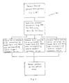
- Fig. 5 is a flowchart that illustrates a method for positioning a patient table.
- inertial coordinate system 100 shows a rigid body 102 with a point P.
- the inertial coordinate system 100 has X-coordinate and Y-coordinate axes.
- Point P of the rigid body 102 is located at X-coordinate X p and Y-coordinate Y p .
- the angle theta characterizes rotation of the rigid body 102 relative to the inertial coordinate system 100 and is defined as a counterclockwise rotation about a Z-coordinate axis (not shown).
- the X p and Y p coordinates of the point P along with the angle ⁇ or (“theta”)" form an independent set of three parameters describing the rigid body's 102 position in the plane, as it moves with XY planar motion with three independent degrees of freedom (X, Y, theta).
- the X direction is generally referred to below as the longitudinal direction
- the Y direction is generally referred to as the elevation direction
- theta represents tilt.
- the multi-axis global positioner patient platform 200 includes a patient table 202 and a base 204.
- a first actuator drive 206 has a variable length R2.
- a second actuator drive 210 has a variable length R4.
- the first actuator drive 206 and the second actuator drive 210 are disposed a distance r3 from each other at the patient table 202, and a distance rl at the base 204.
- a third actuator drive 220 has a variable length R0 and has one end 212 disposed at location "a" of the first actuator drive 206 and a second end 214 disposed at a distance B along the base 204. Distance B may be varied.
- a virtual arbitrary tilt center (P) is shown at coordinates X, Y, and theta, and is analogous to point P in Fig. 1 above.
- the virtual arbitrary tilt center (P) is located a distance P, along the patient table 202, from the first actuator drive 206.
- the first actuator drive 206 connects to the base 204 and the patient table 202.
- the second actuator drive 210 is connected to the base 204 at location r1, and the patient table 202 at location r3. In the embodiment shown in Fig. 2, the second actuator drive 210 is substantially parallel to the first actuator drive 206. However, the second actuator drive 210 is not limited to such an orientation.
- the third actuator drive 220 is connected to the base 204 at location B at one end 214 and the first actuator drive 206 at location "a" at the other end 212. Movement of the patient table 202 in three independent degrees of freedom is effected by extending or contracting, in combination or independently, either the first actuator drive 206, the second actuator drive 210, or the third actuator drive 220. These changes permit independent or combined adjustments to the elevation (Y), tilt (theta), or longitudinal position (X) of the patient table 202.
- the first actuator drive 206, the second actuator drive 210, and the third actuator drive 220 have their respective lengths R2, R4, and R0 controlled according to the following Transfer Functions:
- R 2 ( Y - P ⁇ sin( ⁇ )) 2 +( X - P ⁇ cos( ⁇ )) 2
- R 4 ( Y +( r 3- P ) ⁇ sin( ⁇ )) 2 +(( X - r 1)+( r 3- P ) ⁇ cos( ⁇ )) 2
- R0 a 2 + B 2 - 2 ⁇ a ⁇ B ⁇ ( X-P ⁇ cos( ⁇ )) ( Y-P ⁇ sin( ⁇ )) 2 +( X-P ⁇ cos( ⁇ )) 2
- an associated control system may determine the R0, R2, and R4 actuator extensions from the transfer functions. The control system may then control the actuator drives 206, 210, and 220 to the determined R0, R2, and R4.
- an' additional degree of freedom i.e., roll of the patient table 202
- the first actuator drive 206 is connected to the patient table 202 at one end 216 using a single point connection and is connected at a second end 208 to the base 204 by two points establishing an axis rotation.
- the second actuator drive 210 is divided into two separate actuator drives (R4, R5), each of which is connected to the patient table at one end 218 through a single point connection.
- the third actuator drive 220 is disposed as discussed above.
- the multi-axis global positioner patient platform 300 includes a patient table 302 and a base 304.
- a first actuator drive 306 has a variable length R2.
- a second actuator drive 310 has a variable length R4.
- the first actuator drive 306 and the second actuator drive 310 are disposed a distance r3 from each other at the patient table 302, and a distance r1 at the base 304.
- a third actuator drive 318 has a variable length R0 and is positioned at one end at approximately the same longitudinal position as a first end of the first actuator drive 308, and is positioned at the other end at approximately the same longitudinal position as the second end of the second actuator drive 312.
- a virtual arbitrary tilt center (P) is shown located at coordinates X, Y, and theta, and is analogous to point P in Fig. 1 above.
- the virtual arbitrary tilt center (P) is located a distance P, along the patient table 302, from the first actuator drive 306.
- the first actuator drive 306 is connected to the base 304 and the patient table 302.
- the second actuator drive 310 is connected to the base 304 at location r1, and the patient table 302 at location r3.
- the third actuator drive 310 is connected to the base 304 at approximately the same longitudinal position as the second end of the second actuator drive 312, and at the other end is positioned at approximately the same longitudinal position as the first end of the first actuator drive 308.
- the virtual arbitrary tilt center (P) is located on the patient table 302. Movement of the patient table 302 in three independent degrees of freedom can be effected by extending or contracting, in combination or independently, either the first actuator drive 306, the second actuator drive 310, or the third actuator drive 318.
- the first actuator drive 306, the second actuator drive 310, and the third actuator drive 318 have their respective lengths R2, R4, and R0 controlled according to the following Transfer Functions:
- R 2 ( Y - P ⁇ sin( ⁇ )) 2 + ( X - P ⁇ cos( ⁇ )) 2
- R 4 ( Y +( r 3- P ) ⁇ sin( ⁇ )) 2 +(( X -r1)+( r 3- P ) ⁇ cos( ⁇ )) 2
- an additional degree of freedom i.e., roll of the patient table 302
- the first actuator drive 306 is connected to the patient table 302 at a single point connection 314.
- the second actuator drive 310 is divided into two separate actuator drives (R4, R5), each of which is connected to the patient table 302 through single point connections 316.
- the third actuator drive 318 is disposed as discussed above.
- the multi-axis global positioner patient platform 400 includes a patient table 402, a base 404, a patient table pivot 412, and a base pivot 414.
- a first actuator drive 406 is shown disposed a distance Z from the end of the patient table 402.
- a third actuator drive 408 is positioned at one end to base 404 and to the first actuator drive 406 at the other end.
- the first actuator drive 406 is illustrated in Fig. 4 as being disposed within a support member 410 that provides for lateral stability of the patient table 402.
- the first actuator drive 406 connects to the patient table 402 at one end 412 and the base 404 at another end 414.
- the support member 410 connects to the patient table 402 and the base 404, and provides for lateral stability of the patient table.
- the patient table 402 pivots about the patient table pivot 412 and the base pivot 414.
- the virtual arbitrary tilt center (P) is located a distance Z from the edge of the patient table 402.
- a flowchart 500 illustrates a preferred embodiment of a method for positioning a patient table.
- the method comprises the first step of selecting a desired patient table position (X, Y, theta).
- the next step in the method of positioning the patient table involves determining the actuator extensions, e.g., R0, R2, R4, using the transfer functions.
- the next step in the method of positioning the patient table involves extending, if necessary, an end of a first actuator drive connected between the base and the patient table and the corresponding lateral support actuator drive.
- the next step in positioning the patient table involves extending, if necessary, a second actuator drive connected between the base and the table and the corresponding lateral support actuator drive.
- the next step in the method of positioning the patient table involves extending, if necessary, a third actuator drive connected between the base and the table and the corresponding lateral support actuator drive.
- the end of the first actuator drive and the end of the second actuator drive can be extended simultaneously, at different times, to different lengths, or at different rates to achieve rotational or elevational translation of the patient table.
- the third actuator drive can be extended simultaneous with the first and second aqtuator drives, or at different times, to different lengths, or at different rates to achieve rotational or longitudinal translation of the patient table.
- the present invention thereby provides a method and apparatus for positioning a patient table in multiple independent degrees of freedom.
- the positioning is achieved by changing the lengths of multiple actuator drives in accordance with predetermined transfer functions R0, R2, and R4. Prior limitations on patient access and limited range of motion of the patient table are eliminated.
Landscapes
- Health & Medical Sciences (AREA)
- Life Sciences & Earth Sciences (AREA)
- Engineering & Computer Science (AREA)
- Animal Behavior & Ethology (AREA)
- Veterinary Medicine (AREA)
- Public Health (AREA)
- Biomedical Technology (AREA)
- General Health & Medical Sciences (AREA)
- Medical Informatics (AREA)
- Surgery (AREA)
- Physics & Mathematics (AREA)
- Molecular Biology (AREA)
- Heart & Thoracic Surgery (AREA)
- Pathology (AREA)
- Biophysics (AREA)
- High Energy & Nuclear Physics (AREA)
- Nuclear Medicine, Radiotherapy & Molecular Imaging (AREA)
- Optics & Photonics (AREA)
- Radiology & Medical Imaging (AREA)
- Accommodation For Nursing Or Treatment Tables (AREA)
- Radiation-Therapy Devices (AREA)
- Apparatus For Radiation Diagnosis (AREA)
Abstract
Description
Claims (14)
- A multi-axis positioner patient platform comprising:a patient table;a first actuator drive having a first end connected to the patient table and a second end connected to a base;a second actuator drive having a first end connected to the patient table and a second end connected to the base; anda third actuator drive having a first end connected to the first actuator drive and a second end connected to the base.
- The multi-axis positioner patient platform of claim 1 wherein the first end of the third actuator drive is positioned approximately at a common longitudinal position as the first end of the first actuator drive.
- The multi-axis positioner patient platform of claim 2 wherein the second end of the third actuator drive and the second end of the second actuator drive are positioned at approximately a common longitudinal position.
- The multi-axis positioner patient platform of claim 1 wherein the first, second, and third actuator drives are selected from the group of mechanical, hydraulic, and pneumatic actuators.
- The multi-axis positioner patient platform of claim 1 wherein the first, second, and third actuator drives are each disposed within a support member providing lateral stability.
- A multi-axis positioner patient platform comprising:a patient table;a first actuator drive having a first end connected to the patient table and a second end connected to a base;a second actuator drive having a first end connected to the patient table and a second end connected to the base;a third actuator drive having a first end positioned at approximately the same longitudinal position as the first end of the first actuator drive and a second end positioned at approximately the same longitudinal position as the second end of the second actuator drive.
- The multi-axis positioner patient platform of claim 6 wherein the first end of the third actuator drive is connected to the first end of the first actuator drive.
- The multi-axis positioner patient platform of claim 6 wherein the first, second, and third actuator drives are selected from the group of mechanical, hydraulic, and pneumatic actuators.
- The multi-axis positioner patient platform of claim 6 wherein the first, second, and third actuator drives are each disposed within a support member providing lateral stability.
- A method of positioning a patient table, the method comprising the steps of:extending an end of a first actuator drive connected to a patient table and a base to a first extension;extending an end of a second actuator drive connected to the patient table and the base to a second extension; andextending an end of a third actuator drive connected to the first actuator drive to a third extension.
- The method of claim 10 wherein the end of the first actuator drive and the end of the second actuator drive are extended at the same time to provide rotation or elevational translation of the patient table.
- The method of claim 11 wherein the end of the third actuator drive is extended at the same time to provide rotation or longitudinal translation of the patient table.
- The method of claim 11 further comprising the step of selecting a desired position (X, Y, theta) to which to move the patient table.
- The method of claim 13 further comprising the step of determining the first, second, and third extensions according to at least one transfer function.
Applications Claiming Priority (2)
| Application Number | Priority Date | Filing Date | Title |
|---|---|---|---|
| US09/342,986 US6269499B1 (en) | 1999-06-29 | 1999-06-29 | Multi-axis planar mechanism for a positioner patient platform |
| US342986 | 1999-06-29 |
Publications (2)
| Publication Number | Publication Date |
|---|---|
| EP1064881A2 true EP1064881A2 (en) | 2001-01-03 |
| EP1064881A3 EP1064881A3 (en) | 2001-10-31 |
Family
ID=23344184
Family Applications (1)
| Application Number | Title | Priority Date | Filing Date |
|---|---|---|---|
| EP00305465A Withdrawn EP1064881A3 (en) | 1999-06-29 | 2000-06-29 | Multi-axis planar mechanism for a positioner patient platform |
Country Status (4)
| Country | Link |
|---|---|
| US (1) | US6269499B1 (en) |
| EP (1) | EP1064881A3 (en) |
| JP (1) | JP2001137299A (en) |
| CN (1) | CN1279053A (en) |
Cited By (4)
| Publication number | Priority date | Publication date | Assignee | Title |
|---|---|---|---|---|
| WO2003030802A3 (en) * | 2001-10-08 | 2003-05-22 | Eschmann Holdings Ltd | Surgical tables |
| WO2003053520A3 (en) * | 2001-12-12 | 2004-02-19 | Medical Intelligence Medizinte | Radiotherapy system |
| WO2008041092A3 (en) * | 2006-10-05 | 2008-06-05 | Sala Remo | Patient positioning and moving system for radiotherapy |
| US7789560B2 (en) | 2001-10-30 | 2010-09-07 | Loma Linda University Medical Center | Method and device for delivering radiotherapy |
Families Citing this family (20)
| Publication number | Priority date | Publication date | Assignee | Title |
|---|---|---|---|---|
| US6152599A (en) * | 1998-10-21 | 2000-11-28 | The University Of Texas Systems | Tomotherapy treatment table positioning device |
| US6640363B1 (en) | 2000-10-16 | 2003-11-04 | Ge Medical Systems Global Technology Company, Llc | Mobile imaging table pivot mechanism |
| ES2215813T3 (en) | 2001-03-05 | 2004-10-16 | Brainlab Ag | METHOD FOR CREATING OR UPDATING A RADIATION TREATMENT PLAN. |
| US7028356B2 (en) | 2002-11-26 | 2006-04-18 | Ge Medical Systems Global Technology Company, Llc | Multiconfiguration braking system |
| US6651279B1 (en) | 2002-11-26 | 2003-11-25 | Ge Medical Systems Global Technology Company, Llc | Method and apparatus for collision avoidance in a patient positioning platform |
| US6986179B2 (en) * | 2002-11-26 | 2006-01-17 | Ge Medical Systems Global Technology Company, Llc | Grouted tilting patient positioning table for vascular applications |
| US7125167B2 (en) * | 2003-03-04 | 2006-10-24 | Ge Medical Systems Global Technology Company, Llc | Method and apparatus for tilting in a patient positioning system |
| US6857147B2 (en) | 2003-03-04 | 2005-02-22 | Ge Medical Systems Global Technology Company, Llc | Synchronization drive for a longitudinal axis telescopic guidance mechanism |
| US7173265B2 (en) | 2003-08-12 | 2007-02-06 | Loma Linda University Medical Center | Modular patient support system |
| US7073508B2 (en) | 2004-06-25 | 2006-07-11 | Loma Linda University Medical Center | Method and device for registration and immobilization |
| US7373676B2 (en) * | 2006-09-21 | 2008-05-20 | Aktina Medical Corporation | Patient support apparatus and method therefor |
| EP2095374A4 (en) | 2006-11-21 | 2012-05-30 | Univ Loma Linda Med | DEVICE AND METHOD FOR IMMOBILIZATION OF PATIENTS FOR MAMMARY RADIOTHERAPY |
| US20080116351A1 (en) * | 2006-11-22 | 2008-05-22 | General Electric Company | Gantry system for imaging device |
| US7992239B2 (en) * | 2007-08-20 | 2011-08-09 | Hill-Rom Services, Inc. | Laterally rotating patient support apparatus |
| EP2133056A3 (en) * | 2008-06-13 | 2011-05-04 | Hill-Rom Services, Inc. | Transport apparatus |
| US9693915B2 (en) * | 2009-04-30 | 2017-07-04 | Hill-Rom Services, Inc. | Transfer assist apparatus |
| JP5873256B2 (en) * | 2011-05-23 | 2016-03-01 | 株式会社東芝 | X-ray diagnostic equipment |
| US10888483B2 (en) * | 2016-01-12 | 2021-01-12 | Virginia Commonwealth University | Systems, devices, and methods for position monitoring and motion compensation |
| US11672718B2 (en) * | 2019-09-25 | 2023-06-13 | Warsaw Orthopedic, Inc. | Reconfigurable upper leg support for a surgical frame |
| CN113967034B (en) * | 2021-10-27 | 2024-02-06 | 西安诚挚沃德科技有限公司 | Medical diagnosis platform based on 5G and application method thereof |
Family Cites Families (20)
| Publication number | Priority date | Publication date | Assignee | Title |
|---|---|---|---|---|
| NL292956A (en) * | 1962-05-18 | |||
| US3393004A (en) * | 1966-10-06 | 1968-07-16 | Simmons Co | Hydraulic lift system for wheel stretchers |
| FR96192E (en) * | 1968-12-20 | 1972-05-19 | Bracq Etienne Joseph Jean | Apparatus in particular for transporting patients. |
| DE1903929B2 (en) * | 1969-01-27 | 1978-09-28 | Christian Miesen Fahrzeug- Und Karosseriewerk Gmbh, 5300 Bonn | Tilting and height adjustable stretcher support frame - includes parallelogram linkage and two pneumatic cylinders between top and bottom frames |
| FI59335C (en) * | 1972-07-03 | 1981-08-10 | Stierlen Maquet Ag | MEDICINKS APPARAT MED HYDRAULISKT ROERLIGA ELEMENT |
| US3900906A (en) * | 1974-04-18 | 1975-08-26 | Century Mfg Co | Adjustable bed |
| FR2419068A1 (en) * | 1978-03-07 | 1979-10-05 | Forez Ateliers Haut | Bed mattress with adjustable height and inclination - has non-vertical levers hinging near mattress ends with bases held by spring-loaded racks |
| DE2816564A1 (en) * | 1978-04-17 | 1979-10-25 | Dieter Prof Dipl Ing Maute | Stretcher support for road vehicle - has ram controlled via servo valve by detector which senses vertical movement |
| FR2548016B1 (en) * | 1983-06-30 | 1985-11-29 | Alm | MULTIPLE DEGREE OF INSTALLATION SUCH AS SURGICAL OPERATING TABLE |
| JPS60126142A (en) * | 1983-12-09 | 1985-07-05 | 横河メディカルシステム株式会社 | Table mechanism |
| EP0366878A1 (en) * | 1988-11-04 | 1990-05-09 | Firma Carl Zeiss | Operating table |
| GB9020048D0 (en) * | 1990-09-13 | 1990-10-24 | Hoskins Ltd | Supporting appliance |
| US5398356A (en) * | 1993-06-28 | 1995-03-21 | Pfleger; Frederick W. | X-ray table |
| DE4341779C2 (en) * | 1993-12-08 | 1995-12-07 | Knapp Juergen Michael | Lifting column for a lifting and lowering support element, in particular for a storage area of a patient bed or for industrial applications and a patient bed with such a lifting column |
| DE4423402C2 (en) * | 1994-07-04 | 1999-12-30 | Maquet Ag | Support column for holding a patient support surface |
| US5572567A (en) | 1994-12-08 | 1996-11-05 | Continental X-Ray Corp. | Universal radiographic room |
| US5636259A (en) | 1995-05-18 | 1997-06-03 | Continental X-Ray Corporation | Universal radiographic/fluoroscopic digital room |
| US5657498A (en) * | 1995-11-20 | 1997-08-19 | General Electric Company | Methods and apparatus for acquiring table elevation information |
| US5680430A (en) | 1996-04-23 | 1997-10-21 | Continental X-Ray Corporation | Method and apparatus for controlling and optimizing output of an x-ray source |
| EP0847740A1 (en) * | 1996-11-13 | 1998-06-17 | Jean Roger Batifouyé | Sagitally tiltable bed or examination table |
-
1999
- 1999-06-29 US US09/342,986 patent/US6269499B1/en not_active Expired - Fee Related
-
2000
- 2000-06-29 CN CN00118462A patent/CN1279053A/en active Pending
- 2000-06-29 EP EP00305465A patent/EP1064881A3/en not_active Withdrawn
- 2000-06-29 JP JP2000195379A patent/JP2001137299A/en not_active Withdrawn
Cited By (6)
| Publication number | Priority date | Publication date | Assignee | Title |
|---|---|---|---|---|
| WO2003030802A3 (en) * | 2001-10-08 | 2003-05-22 | Eschmann Holdings Ltd | Surgical tables |
| US7789560B2 (en) | 2001-10-30 | 2010-09-07 | Loma Linda University Medical Center | Method and device for delivering radiotherapy |
| US8083408B2 (en) | 2001-10-30 | 2011-12-27 | Loma Linda University Medical Center | Method and device for delivering radiotherapy |
| US8376613B2 (en) | 2001-10-30 | 2013-02-19 | Loma Linda University Medical Center | Method and device for delivering radiotherapy |
| WO2003053520A3 (en) * | 2001-12-12 | 2004-02-19 | Medical Intelligence Medizinte | Radiotherapy system |
| WO2008041092A3 (en) * | 2006-10-05 | 2008-06-05 | Sala Remo | Patient positioning and moving system for radiotherapy |
Also Published As
| Publication number | Publication date |
|---|---|
| EP1064881A3 (en) | 2001-10-31 |
| JP2001137299A (en) | 2001-05-22 |
| CN1279053A (en) | 2001-01-10 |
| US6269499B1 (en) | 2001-08-07 |
Similar Documents
| Publication | Publication Date | Title |
|---|---|---|
| EP1064881A2 (en) | Multi-axis planar mechanism for a positioner patient platform | |
| CN112423694B (en) | Robot arm structure and manipulator of surgical robot including the same | |
| KR101602241B1 (en) | 5 robotic arm with five-bar spherical linkage | |
| US10029367B2 (en) | System and method for managing multiple null-space objectives and constraints | |
| US9844415B2 (en) | Systems and methods for facilitating access to edges of cartesian-coordinate space using the null space | |
| US9510911B2 (en) | System and methods for managing multiple null-space objectives and SLI behaviors | |
| US10201390B2 (en) | Command shaping to dampen vibrations in mode transitions | |
| KR102186510B1 (en) | Redundant axis and degree of freedom for hardware-constrained remote center robotic manipulator | |
| EP0759285A2 (en) | Mini C-arm assembly for mobile X-ray imaging system | |
| JPH0630952A (en) | Tactical orbital device | |
| US20110245844A1 (en) | Medical robot system | |
| KR101812297B1 (en) | Master manipulation device for robot and control method of surgical robot having the same | |
| CN112155739A (en) | System and method for providing feedback during manual joint positioning | |
| BRPI1011053B1 (en) | ROBOTIC SYSTEM FOR LAPAROSCOPIC SURGERY | |
| KR20150045468A (en) | Movable surgical mounting platform controlled by manual motion of robotic arms | |
| CN112006780B (en) | A minimally invasive surgical robot system and a cochlear implant minimally invasive surgical device | |
| CN116322594B (en) | Systems and methods for determining and maintaining a center of rotation | |
| US20220031502A1 (en) | Medical device for eye surgery | |
| CN114191087A (en) | Suspension plate placing mechanism and surgical robot | |
| US5345334A (en) | Mechanical control unit for a surgical microscope connected to a stand | |
| JP2002361578A (en) | Working robot | |
| CN212415897U (en) | Suspension plate placing mechanism and surgical robot | |
| US10335339B1 (en) | Portable examination chair | |
| US20190365487A1 (en) | Articulated apparatus for surgery | |
| US12440288B2 (en) | Articulated positioning system for a scientific or medical tool, robotized positioning assembly comprising same and corresponding method |
Legal Events
| Date | Code | Title | Description |
|---|---|---|---|
| PUAI | Public reference made under article 153(3) epc to a published international application that has entered the european phase |
Free format text: ORIGINAL CODE: 0009012 |
|
| AK | Designated contracting states |
Kind code of ref document: A2 Designated state(s): AT BE CH CY DE DK ES FI FR GB GR IE IT LI LU MC NL PT SE Kind code of ref document: A2 Designated state(s): DE FR |
|
| AX | Request for extension of the european patent |
Free format text: AL;LT;LV;MK;RO;SI |
|
| PUAL | Search report despatched |
Free format text: ORIGINAL CODE: 0009013 |
|
| AK | Designated contracting states |
Kind code of ref document: A3 Designated state(s): AT BE CH CY DE DK ES FI FR GB GR IE IT LI LU MC NL PT SE |
|
| AX | Request for extension of the european patent |
Free format text: AL;LT;LV;MK;RO;SI |
|
| RIC1 | Information provided on ipc code assigned before grant |
Free format text: 7A 61B 6/04 A, 7A 61G 13/02 B, 7A 61B 5/055 B |
|
| 17P | Request for examination filed |
Effective date: 20020502 |
|
| AKX | Designation fees paid |
Free format text: DE FR |
|
| STAA | Information on the status of an ep patent application or granted ep patent |
Free format text: STATUS: THE APPLICATION IS DEEMED TO BE WITHDRAWN |
|
| 18D | Application deemed to be withdrawn |
Effective date: 20060103 |