EP1064863A1 - Device for tensioning lace fastenings, in particular for a sport shoe - Google Patents
Device for tensioning lace fastenings, in particular for a sport shoe Download PDFInfo
- Publication number
- EP1064863A1 EP1064863A1 EP00103849A EP00103849A EP1064863A1 EP 1064863 A1 EP1064863 A1 EP 1064863A1 EP 00103849 A EP00103849 A EP 00103849A EP 00103849 A EP00103849 A EP 00103849A EP 1064863 A1 EP1064863 A1 EP 1064863A1
- Authority
- EP
- European Patent Office
- Prior art keywords
- lace
- lever
- tensioning
- constricting
- tubular body
- Prior art date
- Legal status (The legal status is an assumption and is not a legal conclusion. Google has not performed a legal analysis and makes no representation as to the accuracy of the status listed.)
- Withdrawn
Links
Images


Classifications
-
- A—HUMAN NECESSITIES
- A43—FOOTWEAR
- A43C—FASTENINGS OR ATTACHMENTS OF FOOTWEAR; LACES IN GENERAL
- A43C1/00—Shoe lacing fastenings
-
- A—HUMAN NECESSITIES
- A43—FOOTWEAR
- A43C—FASTENINGS OR ATTACHMENTS OF FOOTWEAR; LACES IN GENERAL
- A43C11/00—Other fastenings specially adapted for shoes
-
- A—HUMAN NECESSITIES
- A43—FOOTWEAR
- A43C—FASTENINGS OR ATTACHMENTS OF FOOTWEAR; LACES IN GENERAL
- A43C7/00—Holding-devices for laces
- A43C7/04—Hinged devices
Definitions
- the present invention relates to a device for tensioning lace fastenings, in particular for sports shoes, according to the preamble of the main claim.
- the problem underlying the present invention is that of producing a device for tensioning lace fastenings which is structurally and functionally designed to overcome the limitations described above with reference to the prior art cited.
- 1 indicates as a whole a device for tensioning a lace fastening, produced according to the present invention.
- the tensioning device 1 comprises a lever 2 provided with two arms 3 and 4, the free ends of which are hinged on a base 5.
- a tie-bar 6 is received between the arms 3 and 4 and is articulated in an intermediate position of the arms, so as to be able to pivot about an articulation axis X substantially parallel to and spaced from the hinge axis Y of the lever 2.
- the tensioning device 1 further comprises a lace-constricting device 7, of conventional type per se, produced in one piece with the tie-bar 6.
- the lace-constricting device 7 in its turn includes a tubular body 8 of substantially conical shape defining an inclined surface 8a and on which, in turn, are defined a first and a second lace passage opening, respectively indicated by 9 and 10, arranged for the passage of one of the ends of a lace 11.
- the lace-constricting device 7 is equipped with locking means 12 for checking the lace 11 jointly with the tubular body 8, and with release means 13 for unlocking the lace 11, allowing it to slide relatively in both directions inside the tubular body 8.
- the locking means 12 comprise a locking member 14 and resilient means 15 associated therewith.
- the resilient means 15 are mounted inside the tubular body 8 so as to extend in the direction of the lace passage opening 9 starting from a retaining recess 16 provided in the tubular body 8 on the opposite side from the opening 9.
- the locking member 14 is associated, for example by way of a form-fit coupling, with the free end of the resilient means 15 and is further linked to guide means 17 which define and limit its travel.
- the guide means 17 have a structure which is conventional per se and may, for example, comprise a pin 18 passing through the lace-constricting device 7 and slidingly engaged in a groove 19 provided therein.
- the groove 19 is provided parallel to the direction Z defined by the direction of extension of the resilient means 15.
- the tensioning device 1 is mounted on a sports shoe, indicated as a whole by 20, provided with a vamp 21 and a lace fastening 22.
- the lace fastening 22 comprises the lace 11, the ends of which are identified by 23 and 24, and a plurality of return means 25, for example holes or eyelets, provided on opposed edges 26 and 27 of the vamp 21.
- the lace 11 is engaged in alternating succession in the return means 25, according to a lacing system which is conventional per se, in order to bring together the edges 26 and 27 when the lace 11 is tensioned.
- a stop 28 which prevents it from unthreading from the terminal return means 25a.
- the end 24, however, is threaded into the lace-constricting device 7 through the lace passage opening 9.
- the release means 13 are acted on so as to displace the locking member 14, by means of the pin 18, along the groove 19 in the direction of the recess 16, contracting the resilient means 15.
- the lace 11 can be tensioned by grasping the end 24 and exerting a first tension on it.
- the release means 13 are released, so that the locking member 14 is forced against the lace 11 by the resilient means 15.
- the locking means 12 do not prevent the advance of the lace 11 along the lace-constricting device 7 since a component of the tensile force acts on the resilient means 15, causing them to contract partially in the direction Z.
- the end 24 is released while the locking means 12 prevent it from unthreading by retaining the lace 11 in the position reached.
- the force exerted by the lace 11 on the locking member 14 has a component concordant with the direction Z of extension of the resilient means 15, thus increasing the action of retaining the lace 11 against the inner wall of the tubular body 8.
- the final clamping of the fastening 22 is obtained by pivoting the lever 2 on the base 5 in the customary manner for the closure of a lever fastening.
- FIG. 7 A first alternative embodiment of the present invention is shown in Fig. 7, in which the same reference numbers correspond to similar details of the example described previously.
- the lace-constricting device 7 is mounted on the base 5 in a position such as to be received between the arms 3 and 4 of the lever 2 when the latter is pivoted into the closure position.
- On the lever 2 there is further provided a plurality of recesses, all indicated by 2a, substantially parallel to the hinge axis Y, to receive the lace 11 at an intermediate portion thereof.
- the end 24 of the lace 11, before being threaded into the lace passage opening 9, is conveniently inserted into one of the recesses 2a of the lever 2 and led in engagement in one of the return means 25 placed on the opposite edge 27 of the vamp 21 from that on which the tensioning device 1 is arranged ( Figure 9).
- the first degree of tension is obtained by pulling the end 24 through the lace-constricting device 7, and the final clamping by pivoting the lever 2 into the closure position, the difference consisting in the fact that the lever 2 acts in tension directly on the lace 11 without the intervention of the lace-constricting device 7.
- the plurality of recesses 2a advantageously provides a further degree of adjustment of the final tensioning of the lace 11.
- a second variant of the present invention shown in Figures 10 and 11, reassumes the characteristics of the previous example, with the difference that the lace-constricting device 7 is mounted on the base 5 in a position alongside the lever 2, so as to make the design thereof independent by freeing both from the need for the form-fit coupling. Also in this case, details analogous to the examples already described are indicated in the drawings with the same reference numbers.
- the tensioning device of the present invention therefore overcomes the limitations encountered with reference to the prior art cited, at the same time offering numerous advantages, including a greater possibility of tensioning of the lace, since, besides the manual action, benefit is also obtained from the action of the lever.
- a second advantage consists in the versatility of the invention which lends itself to differently configured applications on sports shoes provided with lace fastenings, for example the lace-constricting device may be intended to receive both ends of the lace, or the sports shoe may be provided with a tensioning device for each end of the lace.
- a third advantage consists in that a fastening designed in this manner can be partially loosened by acting only on the lever without unlocking the lace-constricting device, thus maintaining the "memory" of the desired final fastening tension.
Landscapes
- Footwear And Its Accessory, Manufacturing Method And Apparatuses (AREA)
- Braiding, Manufacturing Of Bobbin-Net Or Lace, And Manufacturing Of Nets By Knotting (AREA)
Abstract
A tensioning device (1) for lace fastenings,
particularly for sports shoes, is described, comprising a
lever (2) associated with the lace fastening for tensioning
the latter, and with which there is in turn associated a
lace-constricting device (7). The lace-constricting device
is capable of engaging at least one end of the lace (11)
for retaining the latter in a first state of tension of the
fastening, while the final state of tension is obtained by
the action of the lever (2).
Description
- The present invention relates to a device for tensioning lace fastenings, in particular for sports shoes, according to the preamble of the main claim.
- In the field of sports shoes, it is known to produce lace fastenings in which levers are used as means for tensioning the fastening.
- A fastening of this type is described in US Patent No. 4,999,889 in the name of Le Couturer, in which a lever provided with a plurality of recesses regularly spaced from its fulcrum is associated with a sports shoe with lace fastening. According to the teaching proposed by the patent cited, the lace is engaged in one of the said recesses and tensioned by the action of the lever, the degree of tension obtained being greater, the further the recess engaged by the lace is distanced from the fulcrum.
- The lace fastening described with reference to the prior art cited has numerous drawbacks, however, including the limited possibility of tensioning the lace without having recourse to excessively long levers.
- Further drawbacks encountered are the impossibility of effecting continuous variation of the tension of the lace and the inconvenience of use connected with the insertion of the lace in the recesses of the lever.
- The problem underlying the present invention is that of producing a device for tensioning lace fastenings which is structurally and functionally designed to overcome the limitations described above with reference to the prior art cited.
- This problem is solved by the present invention by means of a tensioning device produced according to the claims which follow.
- The characteristics and advantages of the invention will become clear from the detailed description of one of its preferred embodiments, illustrated by way of non-limiting example with reference to the appended drawings, in which:
- Fig. 1 shows a perspective view of a tensioning device for lace fastenings which is produced according to the present invention,
- Figs. 2 and 3 show, respectively, a view in side elevation and a plan view of the device in Fig. 1,
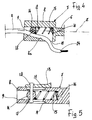
- Fig. 4 shows a view in section along the plane IV-IV of a detail of Fig. 2,
- Fig. 5 shows a view in section along the plane V-V of a detail of Fig. 3,
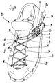
- Fig. 6 shows a sports shoe equipped with the tensioning device in Fig. 1,
- Fig. 7 shows a perspective view from above of a first alternative embodiment of the tensioning device in Fig. 1,
- Fig. 8 shows a view in side elevation, partly in section, of the tensioning device in Fig. 7,
- Fig. 9 shows a perspective view of a shoe equipped with the device in Fig. 7,
- Fig. 10 shows a perspective view from above of a second alternative embodiment of the tensioning device in Fig. 1,
- Fig. 11 shows a view in side elevation, partly in section, of the tensioning device in Fig. 10.
-
- In the drawings, 1 indicates as a whole a device for tensioning a lace fastening, produced according to the present invention.
- The tensioning device 1 comprises a
lever 2 provided with twoarms base 5. - A tie-
bar 6 is received between thearms lever 2. - The tensioning device 1 further comprises a lace-constricting
device 7, of conventional type per se, produced in one piece with the tie-bar 6. The lace-constrictingdevice 7 in its turn includes atubular body 8 of substantially conical shape defining aninclined surface 8a and on which, in turn, are defined a first and a second lace passage opening, respectively indicated by 9 and 10, arranged for the passage of one of the ends of alace 11. - The lace-constricting
device 7 is equipped with locking means 12 for checking thelace 11 jointly with thetubular body 8, and with release means 13 for unlocking thelace 11, allowing it to slide relatively in both directions inside thetubular body 8. The locking means 12 comprise alocking member 14 and resilient means 15 associated therewith. Theresilient means 15 are mounted inside thetubular body 8 so as to extend in the direction of the lace passage opening 9 starting from aretaining recess 16 provided in thetubular body 8 on the opposite side from theopening 9. Thelocking member 14 is associated, for example by way of a form-fit coupling, with the free end of theresilient means 15 and is further linked to guide means 17 which define and limit its travel. The guide means 17 have a structure which is conventional per se and may, for example, comprise apin 18 passing through the lace-constrictingdevice 7 and slidingly engaged in agroove 19 provided therein. Thegroove 19 is provided parallel to the direction Z defined by the direction of extension of theresilient means 15. - With reference to Figure 6, the tensioning device 1 is mounted on a sports shoe, indicated as a whole by 20, provided with a
vamp 21 and a lace fastening 22. The lace fastening 22 comprises thelace 11, the ends of which are identified by 23 and 24, and a plurality of return means 25, for example holes or eyelets, provided onopposed edges vamp 21. - The
lace 11 is engaged in alternating succession in the return means 25, according to a lacing system which is conventional per se, in order to bring together theedges lace 11 is tensioned. - To the free tip of the
end 23 of thelace 11 is fitted astop 28, which prevents it from unthreading from the terminal return means 25a. Theend 24, however, is threaded into the lace-constrictingdevice 7 through the lace passage opening 9. In order to facilitate the insertion operation, the release means 13 are acted on so as to displace thelocking member 14, by means of thepin 18, along thegroove 19 in the direction of therecess 16, contracting theresilient means 15. As soon as theend 24 of thelace 11 has emerged from the opening 10, thelace 11 can be tensioned by grasping theend 24 and exerting a first tension on it. In the meantime, the release means 13 are released, so that thelocking member 14 is forced against thelace 11 by theresilient means 15. In this position the locking means 12 do not prevent the advance of thelace 11 along the lace-constrictingdevice 7 since a component of the tensile force acts on theresilient means 15, causing them to contract partially in the direction Z. Once a first desired degree of tension has been imparted to thelace 11, theend 24 is released while the locking means 12 prevent it from unthreading by retaining thelace 11 in the position reached. In this case, in fact, the force exerted by thelace 11 on thelocking member 14 has a component concordant with the direction Z of extension of theresilient means 15, thus increasing the action of retaining thelace 11 against the inner wall of thetubular body 8. - The final clamping of the
fastening 22 is obtained by pivoting thelever 2 on thebase 5 in the customary manner for the closure of a lever fastening. - To loosen the
fastening 22, it is sufficient to pivot thelever 2 from thebase 5, obtaining a first degree of release of the tension of thelace 11. If it is desired to loosen the shoe further to slip the foot out of it, or even to unthread all or part of thelace 11, the release means 13 will be acted on so as to unlock theend 24 and allow it to slide with respect to the lace-constrictingdevice 7. - A first alternative embodiment of the present invention is shown in Fig. 7, in which the same reference numbers correspond to similar details of the example described previously. According to this alternative, the lace-constricting
device 7 is mounted on thebase 5 in a position such as to be received between thearms lever 2 when the latter is pivoted into the closure position. On thelever 2 there is further provided a plurality of recesses, all indicated by 2a, substantially parallel to the hinge axis Y, to receive thelace 11 at an intermediate portion thereof. According to this alternative, theend 24 of thelace 11, before being threaded into the lace passage opening 9, is conveniently inserted into one of therecesses 2a of thelever 2 and led in engagement in one of the return means 25 placed on theopposite edge 27 of thevamp 21 from that on which the tensioning device 1 is arranged (Figure 9). As in the example described previously, the first degree of tension is obtained by pulling theend 24 through the lace-constrictingdevice 7, and the final clamping by pivoting thelever 2 into the closure position, the difference consisting in the fact that thelever 2 acts in tension directly on thelace 11 without the intervention of the lace-constrictingdevice 7. Furthermore, the plurality ofrecesses 2a advantageously provides a further degree of adjustment of the final tensioning of thelace 11. - A second variant of the present invention, shown in Figures 10 and 11, reassumes the characteristics of the previous example, with the difference that the lace-constricting
device 7 is mounted on thebase 5 in a position alongside thelever 2, so as to make the design thereof independent by freeing both from the need for the form-fit coupling. Also in this case, details analogous to the examples already described are indicated in the drawings with the same reference numbers. - The tensioning device of the present invention therefore overcomes the limitations encountered with reference to the prior art cited, at the same time offering numerous advantages, including a greater possibility of tensioning of the lace, since, besides the manual action, benefit is also obtained from the action of the lever.
- A second advantage consists in the versatility of the invention which lends itself to differently configured applications on sports shoes provided with lace fastenings, for example the lace-constricting device may be intended to receive both ends of the lace, or the sports shoe may be provided with a tensioning device for each end of the lace.
- A third advantage consists in that a fastening designed in this manner can be partially loosened by acting only on the lever without unlocking the lace-constricting device, thus maintaining the "memory" of the desired final fastening tension.
Claims (9)
- A tensioning device (1) for lace fastenings (22), particularly for sports shoes, comprising a lever (2) associated with said lace fastening for tensioning said lace (11), characterized in that it comprises a lace-constricting device (7) capable of engaging at least one end (24) of said lace (11) to retain said lace in a first state of tension, said lever (2) being associated with said lace-constricting device (7) in order to bring said lace (11) into a final state of tension.
- A tensioning device according to claim 1, wherein said lace-constricting device (7) is articulated on said lever (2).
- A tensioning device according to claim 2, wherein said lever (2) comprises a tie-bar (6) articulated in an intermediate position of said lever (2) and said lace-constricting device (7) is associated with said tie-bar (6).
- A tensioning device according to claim 3, wherein said lace-constricting device (7) is produced in one piece with said tie-bar (6).
- A tensioning device according to claim 1, wherein said lever (2) is hinged to a base (5) and said lace-constricting device (7) is mounted on said base (5) to constitute an anchorage point for said at least one end (24) of said lace (11).
- A tensioning device according to claim 5, wherein said lever (2) has at least one recess (2a) for receiving said lace (11) in an intermediate portion thereof.
- A tensioning device according to one of the preceding claims, wherein said lace-constricting device (7) comprises a tubular body (8), constituting said tie-bar (6), provided with at least one opening (9) for receiving at least one end (24) of said lace (11) and means for locking (12) said at least one lace end in said tubular body (8) for firmly retaining said at least one end (24) within said tubular body.
- A tensioning device according to claim 7, wherein on said tubular body (8) there is defined an inclined surface (8a) tapering towards said at least one opening (9) and said locking means (12) comprise a locking member (14) slidable within said tubular body in proximity to said inclined surface (8a) and resilient means (15) urging said locking member (14) towards said at least one opening (9) of said tubular body.
- A sports shoe, comprising a lace fastening (22) and a device (1) for tensioning the latter according to one or more of the preceding claims.
Applications Claiming Priority (2)
| Application Number | Priority Date | Filing Date | Title |
|---|---|---|---|
| ITPD990143 IT1306678B1 (en) | 1999-06-29 | 1999-06-29 | TENSIONING DEVICE FOR STRING LACES, IN PARTICULAR FOR SPORTS FOOTWEAR. |
| ITPD990143 | 1999-06-29 |
Publications (1)
| Publication Number | Publication Date |
|---|---|
| EP1064863A1 true EP1064863A1 (en) | 2001-01-03 |
Family
ID=11392666
Family Applications (1)
| Application Number | Title | Priority Date | Filing Date |
|---|---|---|---|
| EP00103849A Withdrawn EP1064863A1 (en) | 1999-06-29 | 2000-02-24 | Device for tensioning lace fastenings, in particular for a sport shoe |
Country Status (4)
| Country | Link |
|---|---|
| EP (1) | EP1064863A1 (en) |
| JP (1) | JP2001017207A (en) |
| CA (1) | CA2299720A1 (en) |
| IT (1) | IT1306678B1 (en) |
Cited By (11)
| Publication number | Priority date | Publication date | Assignee | Title |
|---|---|---|---|---|
| WO2010087534A1 (en) * | 2009-01-29 | 2010-08-05 | Jung Sung Rok | Device for tightening shoelace |
| US8387282B2 (en) | 2010-04-26 | 2013-03-05 | Nike, Inc. | Cable tightening system for an article of footwear |
| US9326566B2 (en) | 2014-04-15 | 2016-05-03 | Nike, Inc. | Footwear having coverable motorized adjustment system |
| US9365387B2 (en) | 2012-08-31 | 2016-06-14 | Nike, Inc. | Motorized tensioning system with sensors |
| US9532893B2 (en) | 2012-08-31 | 2017-01-03 | Nike, Inc. | Motorized tensioning system |
| US9629418B2 (en) | 2014-04-15 | 2017-04-25 | Nike, Inc. | Footwear having motorized adjustment system and elastic upper |
| US10092065B2 (en) | 2014-04-15 | 2018-10-09 | Nike, Inc. | Footwear having motorized adjustment system and removable midsole |
| WO2018197285A1 (en) * | 2017-04-25 | 2018-11-01 | Selman Cankurt | Quick snap fastener for a lace-up shoe |
| CN110089803A (en) * | 2018-01-31 | 2019-08-06 | 翁中飞 | A kind of shoe buckle as the following formula |
| US11071344B2 (en) | 2012-02-22 | 2021-07-27 | Nike, Inc. | Motorized shoe with gesture control |
| US11684111B2 (en) | 2012-02-22 | 2023-06-27 | Nike, Inc. | Motorized shoe with gesture control |
Families Citing this family (4)
| Publication number | Priority date | Publication date | Assignee | Title |
|---|---|---|---|---|
| DE102005056077B4 (en) * | 2005-11-24 | 2017-05-11 | Deeluxe Sportartikel Handels Gmbh | Boots |
| KR101342854B1 (en) * | 2012-05-04 | 2013-12-17 | 박명호 | lace binder |
| KR101542328B1 (en) * | 2013-09-21 | 2015-08-13 | 김진만 | Device for tightenning up, or loosen a Shoelace |
| KR102443899B1 (en) * | 2020-10-22 | 2022-09-16 | 주식회사 신경 | Wire fastening apparatus |
Citations (4)
| Publication number | Priority date | Publication date | Assignee | Title |
|---|---|---|---|---|
| US2164123A (en) * | 1938-11-21 | 1939-06-27 | Rio Clarence | Fastener for shoelaces |
| FR1589284A (en) * | 1968-10-11 | 1970-03-23 | ||
| EP0286602A2 (en) * | 1987-04-10 | 1988-10-12 | ICARO OLIVIERI & C. S.p.A. | An article of footwear for distance skiing incorporating a self-locking quick fastening device |
| FR2697729A1 (en) * | 1992-11-06 | 1994-05-13 | Salomon Sa | Shoe with tightening system with tension memorization. |
-
1999
- 1999-06-29 IT ITPD990143 patent/IT1306678B1/en active
-
2000
- 2000-02-24 EP EP00103849A patent/EP1064863A1/en not_active Withdrawn
- 2000-02-29 CA CA 2299720 patent/CA2299720A1/en not_active Abandoned
- 2000-03-08 JP JP2000063572A patent/JP2001017207A/en active Pending
Patent Citations (4)
| Publication number | Priority date | Publication date | Assignee | Title |
|---|---|---|---|---|
| US2164123A (en) * | 1938-11-21 | 1939-06-27 | Rio Clarence | Fastener for shoelaces |
| FR1589284A (en) * | 1968-10-11 | 1970-03-23 | ||
| EP0286602A2 (en) * | 1987-04-10 | 1988-10-12 | ICARO OLIVIERI & C. S.p.A. | An article of footwear for distance skiing incorporating a self-locking quick fastening device |
| FR2697729A1 (en) * | 1992-11-06 | 1994-05-13 | Salomon Sa | Shoe with tightening system with tension memorization. |
Cited By (29)
| Publication number | Priority date | Publication date | Assignee | Title |
|---|---|---|---|---|
| WO2010087534A1 (en) * | 2009-01-29 | 2010-08-05 | Jung Sung Rok | Device for tightening shoelace |
| US8387282B2 (en) | 2010-04-26 | 2013-03-05 | Nike, Inc. | Cable tightening system for an article of footwear |
| US9049902B2 (en) | 2010-04-26 | 2015-06-09 | Nike, Inc. | Cable tightening system for an article of footwear |
| US9462851B2 (en) | 2010-04-26 | 2016-10-11 | Nike, Inc. | Cable tightening system for an article of footwear |
| US20240164471A1 (en) * | 2012-02-22 | 2024-05-23 | Nike, Inc. | Motorized shoe with gesture control |
| US11071344B2 (en) | 2012-02-22 | 2021-07-27 | Nike, Inc. | Motorized shoe with gesture control |
| US11684111B2 (en) | 2012-02-22 | 2023-06-27 | Nike, Inc. | Motorized shoe with gesture control |
| US9365387B2 (en) | 2012-08-31 | 2016-06-14 | Nike, Inc. | Motorized tensioning system with sensors |
| US9693605B2 (en) | 2012-08-31 | 2017-07-04 | Nike, Inc. | Footwear having removable motorized adjustment system |
| US10046942B2 (en) | 2012-08-31 | 2018-08-14 | Nike, Inc. | Motorized tensioning system with sensors |
| US10085517B2 (en) | 2012-08-31 | 2018-10-02 | Nike, Inc. | Motorized tensioning system |
| US11786013B2 (en) | 2012-08-31 | 2023-10-17 | Nike, Inc. | Motorized tensioning system with sensors |
| US9532893B2 (en) | 2012-08-31 | 2017-01-03 | Nike, Inc. | Motorized tensioning system |
| US11191322B2 (en) | 2012-08-31 | 2021-12-07 | Nike, Inc. | Motorized tensioning system with sensors |
| US11166525B2 (en) | 2012-08-31 | 2021-11-09 | Nike, Inc. | Footwear having removable motorized adjustment system |
| US10413020B2 (en) | 2012-08-31 | 2019-09-17 | Nike, Inc. | Motorized tensioning system |
| US11044968B2 (en) | 2012-08-31 | 2021-06-29 | Nike, Inc. | Footwear having removable motorized adjustment system |
| US11998086B2 (en) | 2012-08-31 | 2024-06-04 | Nike, Inc. | Motorized tensioning system with sensors |
| US10376018B2 (en) | 2014-04-15 | 2019-08-13 | Nike, Inc. | Footwear having motorized adjustment system and elastic upper |
| US11219276B2 (en) | 2014-04-15 | 2022-01-11 | Nike, Inc. | Footwear having motorized adjustment system and elastic upper |
| US11388957B2 (en) | 2014-04-15 | 2022-07-19 | Nike, Inc. | Footwear having motorized adjustment system and removable midsole |
| US11638465B2 (en) | 2014-04-15 | 2023-05-02 | Nike, Inc. | Footwear having motorized adjustment system and elastic upper |
| US10092065B2 (en) | 2014-04-15 | 2018-10-09 | Nike, Inc. | Footwear having motorized adjustment system and removable midsole |
| US11849811B2 (en) | 2014-04-15 | 2023-12-26 | Nike, Inc. | Footwear having motorized adjustment system and elastic upper |
| US9629418B2 (en) | 2014-04-15 | 2017-04-25 | Nike, Inc. | Footwear having motorized adjustment system and elastic upper |
| US11992095B2 (en) | 2014-04-15 | 2024-05-28 | Nike, Inc. | Footwear having motorized adjustment system and removable midsole |
| US9326566B2 (en) | 2014-04-15 | 2016-05-03 | Nike, Inc. | Footwear having coverable motorized adjustment system |
| WO2018197285A1 (en) * | 2017-04-25 | 2018-11-01 | Selman Cankurt | Quick snap fastener for a lace-up shoe |
| CN110089803A (en) * | 2018-01-31 | 2019-08-06 | 翁中飞 | A kind of shoe buckle as the following formula |
Also Published As
| Publication number | Publication date |
|---|---|
| ITPD990143A1 (en) | 2000-12-29 |
| JP2001017207A (en) | 2001-01-23 |
| IT1306678B1 (en) | 2001-10-02 |
| CA2299720A1 (en) | 2000-12-29 |
Similar Documents
| Publication | Publication Date | Title |
|---|---|---|
| EP1064863A1 (en) | Device for tensioning lace fastenings, in particular for a sport shoe | |
| US9320324B2 (en) | Footwear crampon | |
| US5845371A (en) | Securing device for footwear | |
| KR890002912B1 (en) | Device for fixing a shoe on pedal shoe and pedal this fitted out | |
| US4363498A (en) | Cross country ski binding | |
| JP3054114U (en) | Binding system for articles used for sliding on snow surface | |
| US4351121A (en) | Snowshoe | |
| KR200171552Y1 (en) | Shoe lace binder | |
| EP0787512B1 (en) | Snowboard binding | |
| CA1257963A (en) | Ski boot fastener | |
| US20020007696A1 (en) | Automatic securement device and cyclist's pedal provided with such a device | |
| US6347436B1 (en) | Dual-action buckle | |
| EP0619962B1 (en) | Engagement device particularly for toothed bands for sports shoes | |
| JPS6032441B2 (en) | strap tension buckle | |
| US6105993A (en) | Interface for connecting a boot and a gliding board | |
| US4936603A (en) | Accessory for linking ski tips together | |
| US3936064A (en) | Safety ski binding | |
| EP1997397A1 (en) | A fastening system for fastening a mountaineering boot to a mountaineering ski | |
| US3956796A (en) | Lacing device for ski boots | |
| EP0400213A1 (en) | An adjustable fastening device for sport shoes, and sport shoe incorporating said device | |
| US6571438B2 (en) | Double-bow shoe lace device | |
| US6631927B1 (en) | Ski pole handle | |
| US3401432A (en) | Fastening device for shoes, particularly for ski and mountaineering shoes | |
| US4036510A (en) | Safety ski binding | |
| EP0410091A2 (en) | Rear-entry ski boot |
Legal Events
| Date | Code | Title | Description |
|---|---|---|---|
| PUAI | Public reference made under article 153(3) epc to a published international application that has entered the european phase |
Free format text: ORIGINAL CODE: 0009012 |
|
| AK | Designated contracting states |
Kind code of ref document: A1 Designated state(s): DE FR IT |
|
| AX | Request for extension of the european patent |
Free format text: AL;LT;LV;MK;RO;SI |
|
| 17P | Request for examination filed |
Effective date: 20010322 |
|
| AKX | Designation fees paid |
Free format text: DE FR IT |
|
| STAA | Information on the status of an ep patent application or granted ep patent |
Free format text: STATUS: THE APPLICATION IS DEEMED TO BE WITHDRAWN |
|
| 18D | Application deemed to be withdrawn |
Effective date: 20020903 |