EP1064688B1 - Battery with top and bottom connecting straps and additional vertical connecting bars - Google Patents
Battery with top and bottom connecting straps and additional vertical connecting bars Download PDFInfo
- Publication number
- EP1064688B1 EP1064688B1 EP99901759A EP99901759A EP1064688B1 EP 1064688 B1 EP1064688 B1 EP 1064688B1 EP 99901759 A EP99901759 A EP 99901759A EP 99901759 A EP99901759 A EP 99901759A EP 1064688 B1 EP1064688 B1 EP 1064688B1
- Authority
- EP
- European Patent Office
- Prior art keywords
- battery
- plates
- positive
- edges
- lead
- Prior art date
- Legal status (The legal status is an assumption and is not a legal conclusion. Google has not performed a legal analysis and makes no representation as to the accuracy of the status listed.)
- Expired - Lifetime
Links
- 239000000463 material Substances 0.000 claims abstract description 16
- RYGMFSIKBFXOCR-UHFFFAOYSA-N Copper Chemical compound [Cu] RYGMFSIKBFXOCR-UHFFFAOYSA-N 0.000 claims description 12
- 239000010949 copper Substances 0.000 claims description 12
- 229910052802 copper Inorganic materials 0.000 claims description 12
- 239000002253 acid Substances 0.000 claims description 10
- 239000004411 aluminium Substances 0.000 claims description 3
- 229910052782 aluminium Inorganic materials 0.000 claims description 3
- XAGFODPZIPBFFR-UHFFFAOYSA-N aluminium Chemical compound [Al] XAGFODPZIPBFFR-UHFFFAOYSA-N 0.000 claims description 3
- 229910001369 Brass Inorganic materials 0.000 claims description 2
- 229910000881 Cu alloy Inorganic materials 0.000 claims description 2
- 239000004063 acid-resistant material Substances 0.000 claims description 2
- 239000010951 brass Substances 0.000 claims description 2
- 239000003822 epoxy resin Substances 0.000 claims description 2
- 229920000647 polyepoxide Polymers 0.000 claims description 2
- 229910000838 Al alloy Inorganic materials 0.000 claims 1
- -1 brass Chemical compound 0.000 description 2
- 238000005266 casting Methods 0.000 description 2
- 239000004698 Polyethylene Substances 0.000 description 1
- 229910045601 alloy Inorganic materials 0.000 description 1
- 239000000956 alloy Substances 0.000 description 1
- 238000010276 construction Methods 0.000 description 1
- 238000005260 corrosion Methods 0.000 description 1
- 230000007797 corrosion Effects 0.000 description 1
- 230000008021 deposition Effects 0.000 description 1
- 239000003365 glass fiber Substances 0.000 description 1
- 229910052751 metal Inorganic materials 0.000 description 1
- 239000002184 metal Substances 0.000 description 1
- 238000000034 method Methods 0.000 description 1
- 239000004033 plastic Substances 0.000 description 1
- 229920003023 plastic Polymers 0.000 description 1
- 229920000573 polyethylene Polymers 0.000 description 1
Images

Classifications
-
- H—ELECTRICITY
- H01—ELECTRIC ELEMENTS
- H01M—PROCESSES OR MEANS, e.g. BATTERIES, FOR THE DIRECT CONVERSION OF CHEMICAL ENERGY INTO ELECTRICAL ENERGY
- H01M10/00—Secondary cells; Manufacture thereof
- H01M10/04—Construction or manufacture in general
- H01M10/0436—Small-sized flat cells or batteries for portable equipment
-
- H—ELECTRICITY
- H01—ELECTRIC ELEMENTS
- H01M—PROCESSES OR MEANS, e.g. BATTERIES, FOR THE DIRECT CONVERSION OF CHEMICAL ENERGY INTO ELECTRICAL ENERGY
- H01M10/00—Secondary cells; Manufacture thereof
- H01M10/06—Lead-acid accumulators
- H01M10/12—Construction or manufacture
-
- H—ELECTRICITY
- H01—ELECTRIC ELEMENTS
- H01M—PROCESSES OR MEANS, e.g. BATTERIES, FOR THE DIRECT CONVERSION OF CHEMICAL ENERGY INTO ELECTRICAL ENERGY
- H01M10/00—Secondary cells; Manufacture thereof
- H01M10/06—Lead-acid accumulators
- H01M10/12—Construction or manufacture
- H01M10/126—Small-sized flat cells or batteries for portable equipment
-
- H—ELECTRICITY
- H01—ELECTRIC ELEMENTS
- H01M—PROCESSES OR MEANS, e.g. BATTERIES, FOR THE DIRECT CONVERSION OF CHEMICAL ENERGY INTO ELECTRICAL ENERGY
- H01M50/00—Constructional details or processes of manufacture of the non-active parts of electrochemical cells other than fuel cells, e.g. hybrid cells
- H01M50/50—Current conducting connections for cells or batteries
- H01M50/528—Fixed electrical connections, i.e. not intended for disconnection
- H01M50/529—Intercell connections through partitions, e.g. in a battery casing
-
- H—ELECTRICITY
- H01—ELECTRIC ELEMENTS
- H01M—PROCESSES OR MEANS, e.g. BATTERIES, FOR THE DIRECT CONVERSION OF CHEMICAL ENERGY INTO ELECTRICAL ENERGY
- H01M50/00—Constructional details or processes of manufacture of the non-active parts of electrochemical cells other than fuel cells, e.g. hybrid cells
- H01M50/50—Current conducting connections for cells or batteries
- H01M50/531—Electrode connections inside a battery casing
- H01M50/534—Electrode connections inside a battery casing characterised by the material of the leads or tabs
-
- H—ELECTRICITY
- H01—ELECTRIC ELEMENTS
- H01M—PROCESSES OR MEANS, e.g. BATTERIES, FOR THE DIRECT CONVERSION OF CHEMICAL ENERGY INTO ELECTRICAL ENERGY
- H01M10/00—Secondary cells; Manufacture thereof
- H01M10/04—Construction or manufacture in general
- H01M10/0413—Large-sized flat cells or batteries for motive or stationary systems with plate-like electrodes
-
- Y—GENERAL TAGGING OF NEW TECHNOLOGICAL DEVELOPMENTS; GENERAL TAGGING OF CROSS-SECTIONAL TECHNOLOGIES SPANNING OVER SEVERAL SECTIONS OF THE IPC; TECHNICAL SUBJECTS COVERED BY FORMER USPC CROSS-REFERENCE ART COLLECTIONS [XRACs] AND DIGESTS
- Y02—TECHNOLOGIES OR APPLICATIONS FOR MITIGATION OR ADAPTATION AGAINST CLIMATE CHANGE
- Y02E—REDUCTION OF GREENHOUSE GAS [GHG] EMISSIONS, RELATED TO ENERGY GENERATION, TRANSMISSION OR DISTRIBUTION
- Y02E60/00—Enabling technologies; Technologies with a potential or indirect contribution to GHG emissions mitigation
- Y02E60/10—Energy storage using batteries
-
- Y—GENERAL TAGGING OF NEW TECHNOLOGICAL DEVELOPMENTS; GENERAL TAGGING OF CROSS-SECTIONAL TECHNOLOGIES SPANNING OVER SEVERAL SECTIONS OF THE IPC; TECHNICAL SUBJECTS COVERED BY FORMER USPC CROSS-REFERENCE ART COLLECTIONS [XRACs] AND DIGESTS
- Y02—TECHNOLOGIES OR APPLICATIONS FOR MITIGATION OR ADAPTATION AGAINST CLIMATE CHANGE
- Y02P—CLIMATE CHANGE MITIGATION TECHNOLOGIES IN THE PRODUCTION OR PROCESSING OF GOODS
- Y02P70/00—Climate change mitigation technologies in the production process for final industrial or consumer products
- Y02P70/50—Manufacturing or production processes characterised by the final manufactured product
Definitions
- This invention relates to a battery (also known as an accumulator), particularly but not exclusively of the lead acid type.
- One known lead acid battery comprises a plurality of rectangular plates arranged parallel to one another and separated by insulating separating sheets. Alternate plates are positive and negative electrodes respectively, all the positive electrodes being connected together electrically by a first connector and all the negative electrodes being connected together electrically by a second connector, the two connectors being connected to positive and negative terminals respectively.
- the plates all rectangular, are relatively long and narrow, and the connector and/or terminal is connected to a narrow edge, then there is a relatively long conducting path for the current from the area of the plate adjacent the opposite narrow edge to the connector or terminal. Since the conductivity of lead is significantly less than that of a metal such as copper or aluminium, there is a limit to the current carrying capacity of each electrode, since increasing the current increases the heat generated within the plates. Thus, particularly where other factors dictate that a battery has electrodes which are long and narrow, and the terminals or connectors are attached to a narrow edge of the electrodes, and further if the battery is located in a confined space, the limit on the current carrying capacity is a considerable disadvantage.
- EP-A-0442599 discloses a battery having a plurality of alternating positive and negative plates; at least one tab protruding from one edge of each of the positive and negative plates; at least one tab protruding from an opposite edge of each of the positive and negative plates; a pair of negative plate straps connecting together each tab protruding from each negative plate; a pair of positive plate straps connecting together each tab protruding from each positive plate; a first diagonal bar connecting together the pair of negative plate straps; and a second diagonal bar connecting together the pair of positive plate straps.
- the housing also containing a member having a first end and a second end, the first end being electrically connected to the first short edges of the positive plates adjacent one of the two sets of long edges and the second end being electrically connected to the second short edges of the positive plates adjacent the same set of long edges or to the same set of long edges of the positive plates immediately adjacent to the second short edges, the member extending parallel to the said long edges for most of its length and consisting of a material which has a greater conductivity than the material of the positive plates and the negative plates each being substantially the same size and rectangular shape having two long edges and a first short edge and a second short edge, and a further member being provided, the further member having a first end and a second end, the first end being electrically connected to the first short edges of the negative plates and the
- the negative plates and the positive plates may all be substantially the same size and rectangular shape.
- the first short edges of the positive plates may be connected by a first connector which is electrically connected to a positive terminal of the battery.
- the second short edges of the positive plates may be connected by a further connector which is either of the same general material as the positive plates, e.g. in the case of a lead acid battery the material is lead, or, alternatively, of the same general material as the member.
- the member preferably comprises copper, or a copper alloy such as brass, or aluminium or an alloy thereof, covered in a lead sheath.
- the sheath may be covered in an acid resistant covered in a lead sheath.
- the sheath may be covered in an acid resistant material such as an epoxy resin.
- the first embodiment of the invention comprises a lead acid battery 10 having a plurality of plates 11 and 12 alternately interleaved with separators 13 comprising sheets of microporous polyethylene and of nonwoven glass fibre.
- the plates 11 and 12 and separators 13 are positioned in face-to-face arrangement and alternate plates are of positive and negative polarity, the positive plates being indicated by reference numeral 11 and the negative plates by reference numeral 12.
- the plates and separators are housed in a rectangular container of plastics material (not shown) containing acid (not shown).
- All the plates 11 and 12 are generally rectangular in shape and of generally the same size.
- the horizontal top edge 14 and bottom edge 15 of the plates (as shown) are much shorter than the vertical edges 16.
- the positive plates 11 are each provided on the top edge with a tag 17, having two parts 17a and 17b, adjacent a comer with a long edge. Directly below, each positive plate is provided on its lower edge with a tag 18 adjacent the corner with the same long edge.
- the plates are arranged so that the two tags are arranged in two rows, one row directly above the other.
- the negative plates are each formed with one tag 19 having two parts 19a and 19b on the top edge adjacent the comer with a long edge and the plates are arranged so that the tags 19 form a single row parallel to and spaced apart from the row of tags 17 on the upper edges of the positive plates.
- the tags in each upper row lie in general side-by-side arrangement and are each connected by respective connectors 20 and 21.
- Two sets of terminals 22 and 23 are integrally formed with the respective connectors 20 and 21, the connectors and terminals being formed by a casting operation.
- the terminals and connectors are of high conductivity copper, embedded in a lead sheath by a casting process.
- a further connector 24 in the form of a strip of lead or lead-sheathed copper which is connected by means of a member in the form of a strip 25 of lead-sheathed copper to the connector at the top of the positive plates 11.
- the connector 24 and member 25 are joined by any suitable process to one another, to the lower row of tags and to the upper row of tags to make good electrical connections.
- the lead sheath prevents corrosion by the acid.
- the further connector 24 lies in a horizontal plane perpendicular to the plane of the plate and the member 25 lies in a vertical plane perpendicular to the plane of the plate except for a small section 26 where it is curved for connection to the further connector 24.
- the member of the first embodiment is replaced by a lead sheathed copper strip member 28 having the same general shape and dimensions but positioned between a negative plate 12 and a positive plate 11 (as shown) or at one end of the row of plates so as to lie parallel thereto, and separated from the plates by one or more separating sheets.
- the tags 18 on the lower edges of the positive plates 11 are replaced by tags 30 on a longer side, adjacent the comer with the lower edge. These tags 30 are connected to a lead sheathed copper or lead strip connector 27 which lies alongside the longer sides of the plates 11 and 12, rather than alongside the lower edge as in the first embodiment.
- the high conductivity strip member 25 or 28 of copper sheathed with lead may be connected to the lead sheath of the connector 20 or to the copper connector 20 itself.
- the latter construction has the greater conductivity.
Landscapes
- Engineering & Computer Science (AREA)
- Manufacturing & Machinery (AREA)
- Chemical & Material Sciences (AREA)
- Chemical Kinetics & Catalysis (AREA)
- Electrochemistry (AREA)
- General Chemical & Material Sciences (AREA)
- Connection Of Batteries Or Terminals (AREA)
- Electric Clocks (AREA)
- Battery Mounting, Suspending (AREA)
- Ladders (AREA)
- Coupling Device And Connection With Printed Circuit (AREA)
- Primary Cells (AREA)
- Electromechanical Clocks (AREA)
- Secondary Cells (AREA)
- Hybrid Cells (AREA)
Abstract
Description
- This invention relates to a battery (also known as an accumulator), particularly but not exclusively of the lead acid type.
- One known lead acid battery comprises a plurality of rectangular plates arranged parallel to one another and separated by insulating separating sheets. Alternate plates are positive and negative electrodes respectively, all the positive electrodes being connected together electrically by a first connector and all the negative electrodes being connected together electrically by a second connector, the two connectors being connected to positive and negative terminals respectively.
- If the plates, all rectangular, are relatively long and narrow, and the connector and/or terminal is connected to a narrow edge, then there is a relatively long conducting path for the current from the area of the plate adjacent the opposite narrow edge to the connector or terminal. Since the conductivity of lead is significantly less than that of a metal such as copper or aluminium, there is a limit to the current carrying capacity of each electrode, since increasing the current increases the heat generated within the plates. Thus, particularly where other factors dictate that a battery has electrodes which are long and narrow, and the terminals or connectors are attached to a narrow edge of the electrodes, and further if the battery is located in a confined space, the limit on the current carrying capacity is a considerable disadvantage.
- EP-A-0442599 discloses a battery having a plurality of alternating positive and negative plates; at least one tab protruding from one edge of each of the positive and negative plates; at least one tab protruding from an opposite edge of each of the positive and negative plates; a pair of negative plate straps connecting together each tab protruding from each negative plate; a pair of positive plate straps connecting together each tab protruding from each positive plate; a first diagonal bar connecting together the pair of negative plate straps; and a second diagonal bar connecting together the pair of positive plate straps.
- It is an object of the present invention to provide a battery having an improved current carrying capacity.
- In accordance with the invention containing a plurality of positive plates connected in parallel and a plurality of negative plates connected in parallel, the positive plates each being of substantially the same size and rectangular shape having two long edges and a first short edge and a second short edge, and the housing also containing a member having a first end and a second end, the first end being electrically connected to the first short edges of the positive plates adjacent one of the two sets of long edges and the second end being electrically connected to the second short edges of the positive plates adjacent the same set of long edges or to the same set of long edges of the positive plates immediately adjacent to the second short edges, the member extending parallel to the said long edges for most of its length and consisting of a material which has a greater conductivity than the material of the positive plates and the negative plates each being substantially the same size and rectangular shape having two long edges and a first short edge and a second short edge, and a further member being provided, the further member having a first end and a second end, the first end being electrically connected to the first short edges of the negative plates and the second end being electrically connected to the second short edges of the negative plates or to one of the long edges of the negative plates immediately adjacent to the second short edges, the further member consisting of a material which has a greater conductivity than the material of the negative plates.
- The negative plates and the positive plates may all be substantially the same size and rectangular shape.
- The first short edges of the positive plates may be connected by a first connector which is electrically connected to a positive terminal of the battery.
- The second short edges of the positive plates may be connected by a further connector which is either of the same general material as the positive plates, e.g. in the case of a lead acid battery the material is lead, or, alternatively, of the same general material as the member.
- If the battery is a lead acid battery, the member preferably comprises copper, or a copper alloy such as brass, or aluminium or an alloy thereof, covered in a lead sheath. The sheath may be covered in an acid resistant covered in a lead sheath. The sheath may be covered in an acid resistant material such as an epoxy resin.
- Two embodiments of the invention will now be described by way of example only with reference to the accompanying drawings, of which
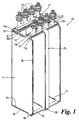
- Figure 1
- shows a perspective view of the interior of a lead acid battery according to the first embodiment of the invention, some of the parts being omitted for clarity; and
- Figure 2
- shows a perspective view of the interior of a battery according to the second embodiment, only the arrangement of positive plates and attachments being shown.
- As shown in Figure 1, the first embodiment of the invention comprises a
lead acid battery 10 having a plurality ofplates separators 13 comprising sheets of microporous polyethylene and of nonwoven glass fibre. Theplates separators 13 are positioned in face-to-face arrangement and alternate plates are of positive and negative polarity, the positive plates being indicated byreference numeral 11 and the negative plates byreference numeral 12. - The plates and separators are housed in a rectangular container of plastics material (not shown) containing acid (not shown).
- All the
plates horizontal top edge 14 andbottom edge 15 of the plates (as shown) are much shorter than thevertical edges 16. Thepositive plates 11 are each provided on the top edge with atag 17, having twoparts tag 18 adjacent the corner with the same long edge. The plates are arranged so that the two tags are arranged in two rows, one row directly above the other. The negative plates are each formed with onetag 19 having twoparts tags 19 form a single row parallel to and spaced apart from the row oftags 17 on the upper edges of the positive plates. - The tags in each upper row lie in general side-by-side arrangement and are each connected by
respective connectors terminals respective connectors - Connected to the lower row of
tags 18 on thepositive plates 11 is afurther connector 24 in the form of a strip of lead or lead-sheathed copper which is connected by means of a member in the form of astrip 25 of lead-sheathed copper to the connector at the top of thepositive plates 11. Theconnector 24 andmember 25 are joined by any suitable process to one another, to the lower row of tags and to the upper row of tags to make good electrical connections. The lead sheath prevents corrosion by the acid. - As can be seen in the drawing, the
further connector 24 lies in a horizontal plane perpendicular to the plane of the plate and themember 25 lies in a vertical plane perpendicular to the plane of the plate except for a small section 26 where it is curved for connection to thefurther connector 24. - In the second embodiment of the invention, shown in Figure 2, the member of the first embodiment is replaced by a lead sheathed
copper strip member 28 having the same general shape and dimensions but positioned between anegative plate 12 and a positive plate 11 (as shown) or at one end of the row of plates so as to lie parallel thereto, and separated from the plates by one or more separating sheets. Thetags 18 on the lower edges of thepositive plates 11 are replaced bytags 30 on a longer side, adjacent the comer with the lower edge. Thesetags 30 are connected to a lead sheathed copper orlead strip connector 27 which lies alongside the longer sides of theplates - In this second embodiment any problems associated with plate growth and/or the deposition of debris, are alleviated.
- In either embodiment the high
conductivity strip member connector 20 or to thecopper connector 20 itself. The latter construction has the greater conductivity.
Claims (14)
- A battery (10) comprising a housing containing a plurality of positive plates (11) connected in parallel and a plurality of negative plates (12) connected in parallel, the positive plates each being of substantially the same size and rectangular shape having two long edges (16a and 16b) and a first short edge (14) and a second short edge (15), characterised in that the housing also contains a member (25;28) having a first end and a second end, the first end being electrically connected to the first short edges (14) of the positive plates (11) adjacent to one of the two sets of long edges (16a) and the second end being electrically connected to the second short edges (15) of the positive plates (11 )adjacent the same set of long edges (16a) or to the same set of long edges (16a) of the positive plates (11) immediately adjacent to the second short edges (15), the member (25;28) extending parallel to the said long edges (16a and 16b) for most its length and consisting of a material which has a greater conductivity than the material of the positive plates (11) and in that the negative plates (12) are each substantially the same size and rectangular shape having two long edges (16) and a first short edge (14) and a second short edge (15), and a further member (25;28) is provided, the further member having a first end and a second end, the first end being electrically connected to the first short edges (14) of the negative plates (12) and the second end being electrically connected to the second short edges (15) of the negative plates (12) or to one of the long edges (16) of the negative plates (12) immediately adjacent to the second short edges (15), the further member (25;28) consisting of a material which has a greater conductivity than the material of the negative plates (12).
- A battery (10) according to Claim 1 characterised in that the negative plates (12) and the positive plates (11) are all substantially the same size and rectangular shape.
- A battery (10) according to either claim 1 or claim 2 characterised in that the first short edges (14) of the positive plates are connected by a connector (20) which is electrically connected to a positive terminal (22) of the battery (10).
- A battery (10) according to any one of the preceding claims characterised in that the second short edges (15) of the positive plates (12) are connected by a further connector (24).
- A battery (10) according to Claim 4 characterised in that the further connector (24) is of the same general material as the positive plates (12).
- A battery (10) according to Claim 4 characterised in that the second connector (24) is of the same general material as the member (25).
- A battery (10) according to any one of the preceding claims which is a lead acid battery.
- A battery (10) according to Claim 7 characterised in that the member (25;28) comprises copper covered in a lead sheath.
- A battery (10) according to claim 8 characterised in that the connector (20) comprises copper covered in lead.
- A battery (10) according to claim 8 or 9 characterised that the positive terminal (22) comprises copper covered in lead.
- A battery (10) according to Claim 7 characterised in that the member (25;28) comprises a copper alloy such as brass, covered in a lead sheath.
- A battery (10) according to Claim 7 characterised in that the member (25;28) comprises aluminium covered in a lead sheath.
- A battery (10) according to Claim 7 characterised in that the member (25;28) comprises an aluminium alloy covered in a lead sheath.
- A battery (10) according to any one of Claims 8 to 11 characterised in that the sheath is covered in an acid resistant material such as an epoxy resin.
Applications Claiming Priority (3)
| Application Number | Priority Date | Filing Date | Title |
|---|---|---|---|
| GBGB9802362.5A GB9802362D0 (en) | 1998-02-04 | 1998-02-04 | Battery |
| GB9802362 | 1998-02-04 | ||
| PCT/GB1999/000194 WO1999040638A1 (en) | 1998-02-04 | 1999-01-20 | Battery with top and bottom connecting straps and additional vertical connecting bars |
Publications (2)
| Publication Number | Publication Date |
|---|---|
| EP1064688A1 EP1064688A1 (en) | 2001-01-03 |
| EP1064688B1 true EP1064688B1 (en) | 2002-06-12 |
Family
ID=10826434
Family Applications (1)
| Application Number | Title | Priority Date | Filing Date |
|---|---|---|---|
| EP99901759A Expired - Lifetime EP1064688B1 (en) | 1998-02-04 | 1999-01-20 | Battery with top and bottom connecting straps and additional vertical connecting bars |
Country Status (11)
| Country | Link |
|---|---|
| US (1) | US6818345B1 (en) |
| EP (1) | EP1064688B1 (en) |
| AT (1) | ATE219297T1 (en) |
| AU (1) | AU2176199A (en) |
| DE (1) | DE69901811T2 (en) |
| DK (1) | DK1064688T3 (en) |
| ES (1) | ES2178377T3 (en) |
| GB (1) | GB9802362D0 (en) |
| PE (1) | PE20000362A1 (en) |
| PT (1) | PT1064688E (en) |
| WO (1) | WO1999040638A1 (en) |
Cited By (1)
| Publication number | Priority date | Publication date | Assignee | Title |
|---|---|---|---|---|
| CN102097659A (en) * | 2011-01-21 | 2011-06-15 | 江苏理士电池有限公司 | Method for manufacturing motorcycle battery with round terminal |
Families Citing this family (3)
| Publication number | Priority date | Publication date | Assignee | Title |
|---|---|---|---|---|
| US6555265B1 (en) | 2000-04-06 | 2003-04-29 | Hawker Energy Products, Inc. | Value regulated lead acid battery |
| US7635537B2 (en) * | 2005-07-05 | 2009-12-22 | Concorde Battery Corporation | Lead-acid storage batteries with lightweight connectors |
| CN102244228A (en) * | 2011-06-15 | 2011-11-16 | 江苏理士电池有限公司 | Manufacturing method of maintenance-free motorcycle battery lead terminal structure |
Family Cites Families (11)
| Publication number | Priority date | Publication date | Assignee | Title |
|---|---|---|---|---|
| US2739997A (en) * | 1952-04-15 | 1956-03-27 | Univ Michigan | Storage battery |
| US3922175A (en) * | 1970-12-14 | 1975-11-25 | Tudor Ab | Plural cell battery |
| US3914134A (en) * | 1974-08-01 | 1975-10-21 | Gen Battery Corp | Through-the-partition battery connections |
| GB1590947A (en) | 1976-11-08 | 1981-06-10 | Auerbach J | Electric batteries |
| SE445276B (en) * | 1981-12-28 | 1986-06-09 | Tudor Ab | BLYACK CUMULATOR WITH BOTTLE CONNECTION |
| ES8609823A1 (en) * | 1985-07-22 | 1986-09-01 | Tudor Acumulador | Electric accumulator battery. |
| DE3610951A1 (en) | 1986-04-02 | 1987-10-08 | Hagen Batterie Ag | NEGATIVE ELECTRODE FOR LEAD ACCUMULATORS |
| JPS63125519A (en) * | 1986-11-14 | 1988-05-28 | Shin Kobe Electric Mach Co Ltd | Epoxy resin composition and lead storage battery prepared therefrom |
| US4983475A (en) | 1990-02-13 | 1991-01-08 | Delans Darwin D | Bar for connecting together two plate straps of the same polarity on an electrochemical battery |
| US5429643A (en) * | 1993-06-02 | 1995-07-04 | Gnb Battery Technologies Inc. | Method of assembling a bipolar lead-acid battery and the resulting bipolar battery |
| US5348817A (en) * | 1993-06-02 | 1994-09-20 | Gnb Battery Technologies Inc. | Bipolar lead-acid battery |
-
1998
- 1998-02-04 GB GBGB9802362.5A patent/GB9802362D0/en not_active Ceased
-
1999
- 1999-01-20 DK DK99901759T patent/DK1064688T3/en active
- 1999-01-20 PT PT99901759T patent/PT1064688E/en unknown
- 1999-01-20 ES ES99901759T patent/ES2178377T3/en not_active Expired - Lifetime
- 1999-01-20 AU AU21761/99A patent/AU2176199A/en not_active Abandoned
- 1999-01-20 US US09/601,477 patent/US6818345B1/en not_active Expired - Fee Related
- 1999-01-20 EP EP99901759A patent/EP1064688B1/en not_active Expired - Lifetime
- 1999-01-20 AT AT99901759T patent/ATE219297T1/en active
- 1999-01-20 DE DE69901811T patent/DE69901811T2/en not_active Expired - Lifetime
- 1999-01-20 WO PCT/GB1999/000194 patent/WO1999040638A1/en not_active Ceased
- 1999-02-04 PE PE1999000089A patent/PE20000362A1/en not_active Application Discontinuation
Cited By (1)
| Publication number | Priority date | Publication date | Assignee | Title |
|---|---|---|---|---|
| CN102097659A (en) * | 2011-01-21 | 2011-06-15 | 江苏理士电池有限公司 | Method for manufacturing motorcycle battery with round terminal |
Also Published As
| Publication number | Publication date |
|---|---|
| PT1064688E (en) | 2002-11-29 |
| US6818345B1 (en) | 2004-11-16 |
| DE69901811D1 (en) | 2002-07-18 |
| EP1064688A1 (en) | 2001-01-03 |
| PE20000362A1 (en) | 2000-06-29 |
| AU2176199A (en) | 1999-08-23 |
| GB9802362D0 (en) | 1998-04-01 |
| DK1064688T3 (en) | 2002-10-14 |
| ATE219297T1 (en) | 2002-06-15 |
| ES2178377T3 (en) | 2002-12-16 |
| DE69901811T2 (en) | 2003-02-20 |
| WO1999040638A1 (en) | 1999-08-12 |
Similar Documents
| Publication | Publication Date | Title |
|---|---|---|
| US8329324B2 (en) | Voltage sensing member and battery module employed with the same | |
| CN111164795B (en) | Battery module | |
| US10910611B2 (en) | Battery block and battery module | |
| CN109690825B (en) | Connection module | |
| EP2187465A1 (en) | Secondary battery pack | |
| EP1059682A1 (en) | Battery pack with modular connectors | |
| KR20070057346A (en) | Manufacturing method of battery core pack | |
| EP2852991A1 (en) | Bimetal buss bar assembly | |
| KR101698772B1 (en) | Battery module having protection device in end block | |
| KR940008154A (en) | Lead Acid Battery Grid | |
| US5149605A (en) | Dual lug battery plate construction | |
| CN106605317A (en) | Assembled battery | |
| WO2009051388A2 (en) | Secondary battery pack having excellent energy density and pcm assembly therefor | |
| EP2182567B1 (en) | Three-dimensional electrode terminal for pouch-typed battery | |
| EP0442599B1 (en) | Electrochemical batteries | |
| KR20230134345A (en) | Series connection apparatus of battery module and battery assembly having this | |
| CN112038676A (en) | Battery | |
| EP1064688B1 (en) | Battery with top and bottom connecting straps and additional vertical connecting bars | |
| EP2337109A2 (en) | Secondary battery pack | |
| US20160268702A1 (en) | Electric wire connection structure | |
| KR20100000888A (en) | Electrical connecting member for battery cell based on physical contact manner | |
| US11982712B2 (en) | Terminal module | |
| EP1228549B1 (en) | Multi-cell battery | |
| EP3471168B1 (en) | Battery module | |
| GB2334138A (en) | Battery |
Legal Events
| Date | Code | Title | Description |
|---|---|---|---|
| PUAI | Public reference made under article 153(3) epc to a published international application that has entered the european phase |
Free format text: ORIGINAL CODE: 0009012 |
|
| 17P | Request for examination filed |
Effective date: 20000814 |
|
| AK | Designated contracting states |
Kind code of ref document: A1 Designated state(s): AT BE CH DE DK ES FI FR GB GR IE IT LI NL PT SE |
|
| 17Q | First examination report despatched |
Effective date: 20010117 |
|
| GRAG | Despatch of communication of intention to grant |
Free format text: ORIGINAL CODE: EPIDOS AGRA |
|
| GRAG | Despatch of communication of intention to grant |
Free format text: ORIGINAL CODE: EPIDOS AGRA |
|
| GRAH | Despatch of communication of intention to grant a patent |
Free format text: ORIGINAL CODE: EPIDOS IGRA |
|
| GRAH | Despatch of communication of intention to grant a patent |
Free format text: ORIGINAL CODE: EPIDOS IGRA |
|
| GRAA | (expected) grant |
Free format text: ORIGINAL CODE: 0009210 |
|
| AK | Designated contracting states |
Kind code of ref document: B1 Designated state(s): AT BE CH DE DK ES FI FR GB GR IE IT LI NL PT SE |
|
| PG25 | Lapsed in a contracting state [announced via postgrant information from national office to epo] |
Ref country code: LI Free format text: LAPSE BECAUSE OF FAILURE TO SUBMIT A TRANSLATION OF THE DESCRIPTION OR TO PAY THE FEE WITHIN THE PRESCRIBED TIME-LIMIT Effective date: 20020612 Ref country code: FI Free format text: LAPSE BECAUSE OF FAILURE TO SUBMIT A TRANSLATION OF THE DESCRIPTION OR TO PAY THE FEE WITHIN THE PRESCRIBED TIME-LIMIT Effective date: 20020612 Ref country code: CH Free format text: LAPSE BECAUSE OF FAILURE TO SUBMIT A TRANSLATION OF THE DESCRIPTION OR TO PAY THE FEE WITHIN THE PRESCRIBED TIME-LIMIT Effective date: 20020612 Ref country code: BE Free format text: LAPSE BECAUSE OF FAILURE TO SUBMIT A TRANSLATION OF THE DESCRIPTION OR TO PAY THE FEE WITHIN THE PRESCRIBED TIME-LIMIT Effective date: 20020612 Ref country code: AT Free format text: LAPSE BECAUSE OF FAILURE TO SUBMIT A TRANSLATION OF THE DESCRIPTION OR TO PAY THE FEE WITHIN THE PRESCRIBED TIME-LIMIT Effective date: 20020612 |
|
| REF | Corresponds to: |
Ref document number: 219297 Country of ref document: AT Date of ref document: 20020615 Kind code of ref document: T |
|
| REG | Reference to a national code |
Ref country code: GB Ref legal event code: FG4D |
|
| REG | Reference to a national code |
Ref country code: CH Ref legal event code: EP |
|
| REF | Corresponds to: |
Ref document number: 69901811 Country of ref document: DE Date of ref document: 20020718 |
|
| REG | Reference to a national code |
Ref country code: IE Ref legal event code: FG4D |
|
| REG | Reference to a national code |
Ref country code: DK Ref legal event code: T3 |
|
| REG | Reference to a national code |
Ref country code: GR Ref legal event code: EP Ref document number: 20020403029 Country of ref document: GR |
|
| ET | Fr: translation filed | ||
| REG | Reference to a national code |
Ref country code: PT Ref legal event code: SC4A Free format text: AVAILABILITY OF NATIONAL TRANSLATION Effective date: 20020911 |
|
| REG | Reference to a national code |
Ref country code: ES Ref legal event code: FG2A Ref document number: 2178377 Country of ref document: ES Kind code of ref document: T3 |
|
| REG | Reference to a national code |
Ref country code: CH Ref legal event code: PL |
|
| PLBE | No opposition filed within time limit |
Free format text: ORIGINAL CODE: 0009261 |
|
| STAA | Information on the status of an ep patent application or granted ep patent |
Free format text: STATUS: NO OPPOSITION FILED WITHIN TIME LIMIT |
|
| 26N | No opposition filed |
Effective date: 20030313 |
|
| PGFP | Annual fee paid to national office [announced via postgrant information from national office to epo] |
Ref country code: IE Payment date: 20030731 Year of fee payment: 5 |
|
| PG25 | Lapsed in a contracting state [announced via postgrant information from national office to epo] |
Ref country code: IE Free format text: LAPSE BECAUSE OF NON-PAYMENT OF DUE FEES Effective date: 20040120 |
|
| REG | Reference to a national code |
Ref country code: IE Ref legal event code: MM4A |
|
| PGFP | Annual fee paid to national office [announced via postgrant information from national office to epo] |
Ref country code: SE Payment date: 20091218 Year of fee payment: 12 |
|
| PGFP | Annual fee paid to national office [announced via postgrant information from national office to epo] |
Ref country code: PT Payment date: 20100113 Year of fee payment: 12 Ref country code: ES Payment date: 20100128 Year of fee payment: 12 |
|
| PGFP | Annual fee paid to national office [announced via postgrant information from national office to epo] |
Ref country code: GR Payment date: 20101221 Year of fee payment: 13 |
|
| PGFP | Annual fee paid to national office [announced via postgrant information from national office to epo] |
Ref country code: DK Payment date: 20110111 Year of fee payment: 13 |
|
| PGFP | Annual fee paid to national office [announced via postgrant information from national office to epo] |
Ref country code: NL Payment date: 20110117 Year of fee payment: 13 Ref country code: IT Payment date: 20110114 Year of fee payment: 13 |
|
| REG | Reference to a national code |
Ref country code: PT Ref legal event code: MM4A Free format text: LAPSE DUE TO NON-PAYMENT OF FEES Effective date: 20110720 |
|
| REG | Reference to a national code |
Ref country code: SE Ref legal event code: EUG |
|
| PG25 | Lapsed in a contracting state [announced via postgrant information from national office to epo] |
Ref country code: PT Free format text: LAPSE BECAUSE OF NON-PAYMENT OF DUE FEES Effective date: 20110720 |
|
| REG | Reference to a national code |
Ref country code: ES Ref legal event code: FD2A Effective date: 20120220 |
|
| PG25 | Lapsed in a contracting state [announced via postgrant information from national office to epo] |
Ref country code: ES Free format text: LAPSE BECAUSE OF NON-PAYMENT OF DUE FEES Effective date: 20110121 |
|
| REG | Reference to a national code |
Ref country code: NL Ref legal event code: V1 Effective date: 20120801 |
|
| REG | Reference to a national code |
Ref country code: DK Ref legal event code: EBP |
|
| REG | Reference to a national code |
Ref country code: GR Ref legal event code: ML Ref document number: 20020403029 Country of ref document: GR Effective date: 20120802 |
|
| PG25 | Lapsed in a contracting state [announced via postgrant information from national office to epo] |
Ref country code: GR Free format text: LAPSE BECAUSE OF NON-PAYMENT OF DUE FEES Effective date: 20120802 Ref country code: IT Free format text: LAPSE BECAUSE OF NON-PAYMENT OF DUE FEES Effective date: 20120120 |
|
| PG25 | Lapsed in a contracting state [announced via postgrant information from national office to epo] |
Ref country code: NL Free format text: LAPSE BECAUSE OF NON-PAYMENT OF DUE FEES Effective date: 20120801 Ref country code: DK Free format text: LAPSE BECAUSE OF NON-PAYMENT OF DUE FEES Effective date: 20120131 |
|
| PG25 | Lapsed in a contracting state [announced via postgrant information from national office to epo] |
Ref country code: SE Free format text: LAPSE BECAUSE OF NON-PAYMENT OF DUE FEES Effective date: 20110121 |
|
| REG | Reference to a national code |
Ref country code: FR Ref legal event code: PLFP Year of fee payment: 18 |
|
| REG | Reference to a national code |
Ref country code: FR Ref legal event code: PLFP Year of fee payment: 19 |
|
| REG | Reference to a national code |
Ref country code: FR Ref legal event code: PLFP Year of fee payment: 20 |
|
| PGFP | Annual fee paid to national office [announced via postgrant information from national office to epo] |
Ref country code: FR Payment date: 20171211 Year of fee payment: 20 |
|
| PGFP | Annual fee paid to national office [announced via postgrant information from national office to epo] |
Ref country code: DE Payment date: 20180110 Year of fee payment: 20 Ref country code: GB Payment date: 20180117 Year of fee payment: 20 |
|
| REG | Reference to a national code |
Ref country code: DE Ref legal event code: R071 Ref document number: 69901811 Country of ref document: DE |
|
| REG | Reference to a national code |
Ref country code: GB Ref legal event code: PE20 Expiry date: 20190119 |
|
| PG25 | Lapsed in a contracting state [announced via postgrant information from national office to epo] |
Ref country code: GB Free format text: LAPSE BECAUSE OF EXPIRATION OF PROTECTION Effective date: 20190119 |