EP1064494B1 - Surgical light apparatus with improved cooling - Google Patents
Surgical light apparatus with improved cooling Download PDFInfo
- Publication number
- EP1064494B1 EP1064494B1 EP99912663A EP99912663A EP1064494B1 EP 1064494 B1 EP1064494 B1 EP 1064494B1 EP 99912663 A EP99912663 A EP 99912663A EP 99912663 A EP99912663 A EP 99912663A EP 1064494 B1 EP1064494 B1 EP 1064494B1
- Authority
- EP
- European Patent Office
- Prior art keywords
- filter
- light source
- light
- filter plates
- reflector
- Prior art date
- Legal status (The legal status is an assumption and is not a legal conclusion. Google has not performed a legal analysis and makes no representation as to the accuracy of the status listed.)
- Expired - Lifetime
Links
- 238000001816 cooling Methods 0.000 title claims description 18
- 230000005855 radiation Effects 0.000 claims abstract description 58
- 230000005540 biological transmission Effects 0.000 claims abstract description 6
- 239000000463 material Substances 0.000 claims abstract description 4
- 239000011248 coating agent Substances 0.000 claims description 6
- 238000000576 coating method Methods 0.000 claims description 6
- 238000001228 spectrum Methods 0.000 claims description 5
- NIXOWILDQLNWCW-UHFFFAOYSA-N acrylic acid group Chemical group C(C=C)(=O)O NIXOWILDQLNWCW-UHFFFAOYSA-N 0.000 claims description 3
- XAGFODPZIPBFFR-UHFFFAOYSA-N aluminium Chemical compound [Al] XAGFODPZIPBFFR-UHFFFAOYSA-N 0.000 claims description 3
- 229910052782 aluminium Inorganic materials 0.000 claims description 3
- 230000000712 assembly Effects 0.000 description 8
- 238000000429 assembly Methods 0.000 description 8
- 239000011521 glass Substances 0.000 description 3
- 229910052736 halogen Inorganic materials 0.000 description 3
- 239000000779 smoke Substances 0.000 description 3
- 125000006850 spacer group Chemical group 0.000 description 3
- 229910052721 tungsten Inorganic materials 0.000 description 3
- 239000010937 tungsten Substances 0.000 description 3
- -1 tungsten halogen Chemical class 0.000 description 3
- 230000004323 axial length Effects 0.000 description 2
- 238000005286 illumination Methods 0.000 description 2
- 230000003287 optical effect Effects 0.000 description 2
- 230000000717 retained effect Effects 0.000 description 2
- 238000001356 surgical procedure Methods 0.000 description 2
- 238000010521 absorption reaction Methods 0.000 description 1
- 230000000903 blocking effect Effects 0.000 description 1
- 238000006243 chemical reaction Methods 0.000 description 1
- 238000004140 cleaning Methods 0.000 description 1
- 238000009501 film coating Methods 0.000 description 1
- 238000001914 filtration Methods 0.000 description 1
- 230000003760 hair shine Effects 0.000 description 1
- 230000031700 light absorption Effects 0.000 description 1
- 230000002265 prevention Effects 0.000 description 1
- 230000003595 spectral effect Effects 0.000 description 1
- 239000010409 thin film Substances 0.000 description 1
- 238000002834 transmittance Methods 0.000 description 1
Images



Classifications
-
- F—MECHANICAL ENGINEERING; LIGHTING; HEATING; WEAPONS; BLASTING
- F21—LIGHTING
- F21V—FUNCTIONAL FEATURES OR DETAILS OF LIGHTING DEVICES OR SYSTEMS THEREOF; STRUCTURAL COMBINATIONS OF LIGHTING DEVICES WITH OTHER ARTICLES, NOT OTHERWISE PROVIDED FOR
- F21V9/00—Elements for modifying spectral properties, polarisation or intensity of the light emitted, e.g. filters
- F21V9/04—Elements for modifying spectral properties, polarisation or intensity of the light emitted, e.g. filters for filtering out infrared radiation
-
- F—MECHANICAL ENGINEERING; LIGHTING; HEATING; WEAPONS; BLASTING
- F21—LIGHTING
- F21V—FUNCTIONAL FEATURES OR DETAILS OF LIGHTING DEVICES OR SYSTEMS THEREOF; STRUCTURAL COMBINATIONS OF LIGHTING DEVICES WITH OTHER ARTICLES, NOT OTHERWISE PROVIDED FOR
- F21V14/00—Controlling the distribution of the light emitted by adjustment of elements
- F21V14/02—Controlling the distribution of the light emitted by adjustment of elements by movement of light sources
-
- F—MECHANICAL ENGINEERING; LIGHTING; HEATING; WEAPONS; BLASTING
- F21—LIGHTING
- F21V—FUNCTIONAL FEATURES OR DETAILS OF LIGHTING DEVICES OR SYSTEMS THEREOF; STRUCTURAL COMBINATIONS OF LIGHTING DEVICES WITH OTHER ARTICLES, NOT OTHERWISE PROVIDED FOR
- F21V29/00—Protecting lighting devices from thermal damage; Cooling or heating arrangements specially adapted for lighting devices or systems
- F21V29/50—Cooling arrangements
- F21V29/70—Cooling arrangements characterised by passive heat-dissipating elements, e.g. heat-sinks
- F21V29/83—Cooling arrangements characterised by passive heat-dissipating elements, e.g. heat-sinks the elements having apertures, ducts or channels, e.g. heat radiation holes
-
- F—MECHANICAL ENGINEERING; LIGHTING; HEATING; WEAPONS; BLASTING
- F21—LIGHTING
- F21V—FUNCTIONAL FEATURES OR DETAILS OF LIGHTING DEVICES OR SYSTEMS THEREOF; STRUCTURAL COMBINATIONS OF LIGHTING DEVICES WITH OTHER ARTICLES, NOT OTHERWISE PROVIDED FOR
- F21V29/00—Protecting lighting devices from thermal damage; Cooling or heating arrangements specially adapted for lighting devices or systems
- F21V29/85—Protecting lighting devices from thermal damage; Cooling or heating arrangements specially adapted for lighting devices or systems characterised by the material
-
- F—MECHANICAL ENGINEERING; LIGHTING; HEATING; WEAPONS; BLASTING
- F21—LIGHTING
- F21V—FUNCTIONAL FEATURES OR DETAILS OF LIGHTING DEVICES OR SYSTEMS THEREOF; STRUCTURAL COMBINATIONS OF LIGHTING DEVICES WITH OTHER ARTICLES, NOT OTHERWISE PROVIDED FOR
- F21V7/00—Reflectors for light sources
- F21V7/04—Optical design
- F21V7/09—Optical design with a combination of different curvatures
-
- F—MECHANICAL ENGINEERING; LIGHTING; HEATING; WEAPONS; BLASTING
- F21—LIGHTING
- F21V—FUNCTIONAL FEATURES OR DETAILS OF LIGHTING DEVICES OR SYSTEMS THEREOF; STRUCTURAL COMBINATIONS OF LIGHTING DEVICES WITH OTHER ARTICLES, NOT OTHERWISE PROVIDED FOR
- F21V7/00—Reflectors for light sources
- F21V7/22—Reflectors for light sources characterised by materials, surface treatments or coatings, e.g. dichroic reflectors
- F21V7/24—Reflectors for light sources characterised by materials, surface treatments or coatings, e.g. dichroic reflectors characterised by the material
-
- F—MECHANICAL ENGINEERING; LIGHTING; HEATING; WEAPONS; BLASTING
- F21—LIGHTING
- F21V—FUNCTIONAL FEATURES OR DETAILS OF LIGHTING DEVICES OR SYSTEMS THEREOF; STRUCTURAL COMBINATIONS OF LIGHTING DEVICES WITH OTHER ARTICLES, NOT OTHERWISE PROVIDED FOR
- F21V7/00—Reflectors for light sources
- F21V7/22—Reflectors for light sources characterised by materials, surface treatments or coatings, e.g. dichroic reflectors
- F21V7/28—Reflectors for light sources characterised by materials, surface treatments or coatings, e.g. dichroic reflectors characterised by coatings
-
- F—MECHANICAL ENGINEERING; LIGHTING; HEATING; WEAPONS; BLASTING
- F21—LIGHTING
- F21V—FUNCTIONAL FEATURES OR DETAILS OF LIGHTING DEVICES OR SYSTEMS THEREOF; STRUCTURAL COMBINATIONS OF LIGHTING DEVICES WITH OTHER ARTICLES, NOT OTHERWISE PROVIDED FOR
- F21V21/00—Supporting, suspending, or attaching arrangements for lighting devices; Hand grips
- F21V21/40—Hand grips
- F21V21/403—Hand grips for operation or dentist lamps
-
- F—MECHANICAL ENGINEERING; LIGHTING; HEATING; WEAPONS; BLASTING
- F21—LIGHTING
- F21W—INDEXING SCHEME ASSOCIATED WITH SUBCLASSES F21K, F21L, F21S and F21V, RELATING TO USES OR APPLICATIONS OF LIGHTING DEVICES OR SYSTEMS
- F21W2131/00—Use or application of lighting devices or systems not provided for in codes F21W2102/00-F21W2121/00
- F21W2131/20—Lighting for medical use
- F21W2131/205—Lighting for medical use for operating theatres
-
- Y—GENERAL TAGGING OF NEW TECHNOLOGICAL DEVELOPMENTS; GENERAL TAGGING OF CROSS-SECTIONAL TECHNOLOGIES SPANNING OVER SEVERAL SECTIONS OF THE IPC; TECHNICAL SUBJECTS COVERED BY FORMER USPC CROSS-REFERENCE ART COLLECTIONS [XRACs] AND DIGESTS
- Y10—TECHNICAL SUBJECTS COVERED BY FORMER USPC
- Y10S—TECHNICAL SUBJECTS COVERED BY FORMER USPC CROSS-REFERENCE ART COLLECTIONS [XRACs] AND DIGESTS
- Y10S362/00—Illumination
- Y10S362/804—Surgical or dental spotlight
Definitions
- the present invention relates to a surgical light apparatus, and particularly a surgical light apparatus having improved cooling capability. More particularly, the present invention relates to a lighthead of a surgical light apparatus that blocks radiant heat energy from reaching a target area to be illuminated while providing for cooling of the lighthead.
- Surgical lights used in hospital operating rooms to illuminate surgical sites on patients are known.
- Surgical lights employ one or more lamps, such as a tungsten halogen lamp, that convert electrical input to visible light.
- lamps such as a tungsten halogen lamp
- the conversion of electrical energy to light by a light bulb can be relatively inefficient, and over ninety percent of the input energy can be transmitted from the bulb as radiant heat.
- a surgical light fixture design that relies on flow of external air through the lighthead for cooling can cause the smoke to be drawn inside the lighthead, resulting in deposits from the smoke onto internal components. This can degrade the optical performance and require cleaning of the internal components.
- US 3075071 discloses a surgical light where the light source is surrounded by a lens formed of glass which said to control heat.
- an apparatus for cooling a surgical light fixture having a first light source and an enclosure surrounding the first light source, the enclosure including a reflector and a lens transparent to visible light
- the apparatus is for cooling a surgical light fixture in which the reflector is configured to reflect light from the first light source towards the lens
- the apparatus comprising a plurality of filter elements coupled to the enclosure between the first light source and the reflector, the plurality of filter elements being formed at least in part from material that is substantially transparent to visible light radiation and that substantially blocks transmission of heat energy radiation, and the plurality of filter elements being configured to intersect substantially all radiation from the first light source that otherwise would pass to the reflector and through the lens, the plurality of filter elements being configured to define at least one gap between two adjacent filter elements.
- the filter elements can be configured to provide a gap between each pair of adjacent filter elements.
- the filter elements can be rectangular filter plates. Each filter plate can have substantially the same shape.
- the plurality of filter elements can include a first set of filter plates and a second set of filter plates.
- the first set of filter plates is interleaved with the second set of filter plates so that each filter plate of the first set of filter plates is adjacent two filter plates of the second set of filter plates.
- the adjacent filter plates are separated by a gap.
- the first set of filter plates is arranged in a first pattern and the second set of filter plates is arranged in a second pattern spaced radially outward of the first set of filter plates.
- the plurality of filter elements can include four inner filter plates spaced apart in a first square pattern and four outer filter plates spaced apart in a second square pattern located radially outward of the first square pattern.
- the second square pattern is rotationally offset from the first square pattern by about 45°.
- the plurality of filter elements can include a plurality of filter plates.
- Each filter plate has a front, a back, a first side edge, and a second side edge.
- the plurality of filter plates is arranged in a pattern around the light source with the front of each filter plate facing toward the light source and the back of each filter plate facing away from the light source.
- the first side edge of each filter plate is spaced apart from the second side edge of an adjacent filter plate and located radially inward toward the light source from the second side edge of the adjacent filter plate.
- the filter elements can be configured to block transmission of heat energy radiation from the light source to the reflector substantially over a 360° field of view about a longitudinal axis through the light source.
- the heat energy radiation can include infrared radiation.
- the filter elements can be configured to block radiation having a predefined range of wavelengths.
- the light source can include first and second light sources.
- the first light source has a first longitudinal axis and second light source has a second longitudinal axis that is spaced apart from and parallel to the first longitudinal axis.
- the filter element are configured to block heat energy radiation from the second light source to the reflector substantially over a 360° field of view about the second axis.
- the enclosure can be substantially sealed or hermetically sealed to prevent entry of air into the enclosure.
- the lens can be an acrylic lens and can be substantially transparent to heat energy radiation.
- the reflector can include an aluminum reflecting surface which furthermore can be opaque.
- the reflector can be configured to reflect both visible light and heat energy radiation toward the lens.
- the reflector can be devoid of any coating that selectively filters visible light and heat energy radiation.
- the lens can be substantially transparent to visible light and to heat energy radiation.
- the lens can be devoid of any coating that selectively passes visible light and that blocks heat energy radiation.
- a surgical light system 30 includes a first arm assembly 32, a second arm assembly 34, a first lighthead 36 coupled to first arm assembly 32, and a second lighthead 38 coupled to second arm assembly 34 as shown in Fig. 1.
- First and second arm assemblies 32, 34 each coupled to a common mounting apparatus 42 which is configured to mount to suitable support structure (not shown) associated with a ceiling 44. It is understood that first and second arm assemblies 32, 34 may be mounted to any suitable support such as a wall or separate stand.
- Each arm assembly 32, 34 includes an L-shaped upper or first arm 46, a lower or second arm 48, and a yoke 50.
- Each first arm 46 is independently pivotable relative to mounting apparatus 42 about a vertical pivot axis 52.
- Each second arm 48 is pivotable relative to the respective first arm 46 about a respective horizontal or main pivot axis 54 and about a respective vertical pivot axis 53 that is spaced from pivot axis 52.
- each yoke 50 is pivotable relative to the respective second arm 48 about a respective pivot axis 56 and each of lightheads 36, 38 is pivotable relative to the respective yoke 50 about a respective pivot axis 58.
- arm assemblies 32, 34 and lightheads 36, 38 are movable to a variety of positions relative to ceiling 44.
- Each lighthead 36, 38 includes a dome-shaped housing 60, a lens 62 through which light shines from the respective lighthead 36, 38, and a handle assembly 64 as shown in Fig. 1.
- Each handle assembly 64 includes a handle 66 which is grasped by a surgeon to move the respective lighthead 36, 38 and associated arm assembly 32, 34 to a desired position.
- Each lighthead 36, 38 includes one or more light bulbs (not shown) and each lighthead 36, 38 includes a reflector (not shown) that reflects light emanating from the at least one light bulb to illuminate a surgical site on a patient.
- Each lighthead 36, 38 also includes a light absorption filter (not shown) that is fabricated from specially formulated glass to filter most of the near and intermediate infra-red emissions from the at least one light bulb.
- Handle 66 of each handle assembly 64 is rotatable to move the at least one light bulb relative to the reflector to adjust the pattern size of reflected light that illuminates the surgical site.
- the pattern size may be thought of generally as the diameter of the area illuminated by the associated lighthead 36, 38.
- handle assembly 64 includes a button 74 at the bottom of handle 66 which is pressed to adjust the intensity level at which light emanates from the at least one light bulb.
- Handle assembly 64 includes an escutcheon 76 above handle 66.
- Handle assembly 64 further includes a first set of LED's 78 and a second set of LED's 80 that are visible on respective sides of escutcheon 76 to provide user information regarding the operation of the at least one light bulb and the intensity level at which light is emanating from the at least one light bulb.
- each of the at least one light bulb is a tungsten halogen lamp.
- Surgical light system 30 includes a controller box 82, shown in Fig. 1, which is mounted to a wall 84 or other suitable structure and which is coupled electrically to surgical lightheads 36, 38 to control the operation of the at least one light bulb.
- Controller box 82 includes a control panel 86 having buttons 88 and sets of LED's 90 that are associated with each respective lighthead 36, 38.
- Each set ofLED's 90 is arranged similarly and provides the same information as LED's 78, 80 of the respective lighthead 36, 38.
- each button 86 is pressed to change the light intensity of the at least one light bulb in the same manner that button 74 of the associated lighthead 36, 38 is pressed to change the light intensity of the at least one light bulb.
- Surgical light system 30 optionally may include a task light 92, shown in Fig. 1, and controller box 82 optionally may include a button 94 that is pressed to turn task light 92 on and off.
- Each lighthead 36, 38 includes a combination light and heat radiation filter apparatus 10 as shown in Figs. 2-7.
- Filter apparatus 10 is positioned within housing 60 and configured to encircle light bulbs 68, 70 to intersect light and heat energy radiating from bulbs 68, 70 that otherwise would pass unimpeded towards reflector 72 to be reflected towards lens 62 and out of lighthead 36, 38.
- Filter apparatus 10 illustratively includes a plurality of rectangular filter plates 12 fabricated from specially formulated glass that filters the visible light to produce light of a desired color while absorbing most of the heat energy radiation radiated from either of bulbs 68, 70. It is understood that any suitable material that permits passage of a desired spectrum of visible light while blocking a desired spectrum of heat energy radiation can be used.
- the filter plates 12 can be configured to block a predefined spectrum of heat energy radiation such as infrared radiation.
- filter plates 12 can be configured to filter visible light to remove a predefined spectrum of visible light.
- Filter plates 12 are retained between a pair of plate-receiving assemblies 16, 18 as best shown in Figs. 2-4.
- Upper plate-receiving assembly 16 includes an annular top cover plate 20, an annular bottom plate 22 having plate-receiving slots 23, and an annular gasket 21 configured to lie between top and bottom plates 20, 22. Gasket 21 provides a compressible cushion for filter plates 12 when they are retained within assembly 16 as explained below.
- Top and bottom plates 20, 22 are coupled together by four screws 102.
- Upper plate-receiving assembly 16 is coupled to reflector 72 by four screws 106 and to housing 60 by four screws 108 as shown in Figs. 2 and 3.
- Housing 60 includes a removable top cover 61 to conceal screws 108.
- lower plate-receiving assembly 18 includes an annular bottom cover plate 24, an annular top plate 26 having plate-receiving slots 27, and an annular gasket 25 configured to lie between bottom and top plates 24, 26.
- Gasket 25 performs the same function as gasket 21 above.
- Lower plate-receiving assembly bottom and top plates 24, 26 are similarly coupled together by four screws 104.
- Lightheads 36, 38 include a filter support assembly 110 that includes upper and lower annular support plates 112, 114 spaced apart by spacers 113 as shown in Figs. 2-4.
- Upper and lower plate-receiving assemblies 16, 18 are coupled to upper support plate 112 of filter support assembly 110 by four rod assemblies 116.
- Each rod assembly 116 includes a rod 118 having an upper threaded end 120 and a lower threaded end 122, a filter plate spacing tube 124, a support assembly spacing tube 126, and washers 128 and nuts 130.
- the threaded ends 120 of rods 118 extend through apertures 131 found in top plate 20, gasket 21 and bottom plate 22 to permit attachment of the washers 128 and nuts 130 to the rods 118 as shown in Figs. 2 and 3.
- Filter plate and support assembly spacing tubes 124, 126 are sized so that rod 118 can extend axially through them.
- Filter plate spacing tube 124 has an axial length to space lower plate 22 of upper plate-receiving assembly 16 apart from upper plate 26 of lower plate-receiving assembly 18 so that filter plates 12 are snugly received in plate-receiving slots 23, 27 with gaskets 21, 25 cushioning and protecting the ends of filter plates 12.
- Support assembly spacing tube 126 has an axial length defined by the distance between upper plate 112 of filter support assembly 110 and bottom cover plate 24 of lower plate-retaining assembly 18 when filter 10 is coupled to housing 60 and reflector 72 as shown in Figs. 2 and 3. Washers 128 and nuts 130 are attached to upper and lower threaded ends 120, 122 of rod 118 to secure filter apparatus 10 within lighthead 36, 38.
- Filter support assembly 110 is coupled to the lens 62 by fasteners 140 which extend through mounting plate 142, through plate 114 and into threaded spacers 113 as shown best in Fig. 3. Fasteners 144 extend through plate 112 and into the other threaded end of spacers 113. Therefore the filter apparatus 10 is held in a desired location within an enclosure defined by housing 60 and lens 62.
- Figs. 2-7 eight filter plates 12 are spaced apart in a generally octagonal pattern as best shown in Figs. 4-7, with gaps 14 between adjacent filter plates 12. Gaps 14 between the filter plates 12 advantageously lower the thermal resistance of filter 10 by allowing for flow of air as shown by arrows 40 in Fig. 5. Thus, as air in the vicinity of light bulbs 68, 70 and filter plates 12 increases in temperature due to radiation of heat from bulbs 68, 70 and absorption of heat by filter plates 12, the gaps 14 permit convective airflow across filter apparatus 10 to assist in dissipating heat within lighthead 36.
- the prevention of localized heat buildup within lighthead 36 results in improved operation, such as increased life expectancy for bulbs 68, 70 and a lower overall operating temperature within housing 60.
- the improved cooling permits the use of higher wattage bulbs to provide additional light and improve illumination at a surgical site while maintaining acceptable temperatures with the surgical light apparatus.
- lighthead 36, 38 is sealed against external airflow into the enclosure defined by housing 60 and lens 62, it is understood that convective airflow encouraged by filter apparatus 10 will improve cooling irrespective of whether a lighthead is hermetically sealed, nominally sealed, or passageways for introduction of external air into the lighthead are provided.
- the octagonal shape of Figs. 4-7 includes four inner filter plates 12 spaced apart in a first square pattern and four outer filter plates 12 spaced apart in a second square pattern spaced radially outward of the first square pattern, with the square patterns being rotationally offset by 45°.
- left and right side edges 13, 15 of inner filter plates 12 are positioned radially inward of side edges 13, 15 of the outer filter plates 12.
- each of the eight filter plates 12 can be positioned in an alternative octagonal pattern so that left side edge 13 of each filter plate 12 is spaced apart and radially inward of right side edge 15 of an adjacent filter plate.
- the eight filter plates 12 are each positioned uniformly relative to a geometric center of the pattern of the octagonal pattern with a rotational offset of 45° between adjacent filter plates when viewed from the center of the pattern.
- Main light bulb 68 in preferred embodiments is positioned at the geometric center of the pattern of filter plates 12, as best shown in the octagonal pattern of Fig. 6.
- Filter plates 12 are sized so that left and right side edges 13, 15 of radially inward filter plates 12 block light and heat energy radiation from main light bulb 6& radiating toward left and right side edges 13, 15 of radially outward filter plates as illustrated by radiation lines 132.
- gaps 14 are obscured from a direct line of sight of radiation from main light bulb 68, and light and heat radiation is blocked over a 360° field of view looking radially outward from main light bulb 68.
- left and right side edges 13, 15 of radially inward filter plates 12 block radiation from redundant light bulb 70 radiating toward left and right side edges 13, 15 of radially outward filter plates 12 to block heat energy radiation from the second light source over a 360° field of view looking radially outward from redundant light bulb 70.
- Filter apparatus 10 provides improved cooling so that, for example, a sealed surgical lighthead 36, 38 having a 3150° K tungsten halogen lamp rated between about 180 to about 190 watts can maintain a temperature of less than about 500° F (260°C) for filter plates 12 configured to produce a filtered light color temperature of about 4200° K.
- Filter apparatus 10 provides for a total integrated spectral transmittance (filter lumen output divided by lamp lumen input) of at least about 64% and a maximum heat to light ratio (sum of visible, ultraviolet, and infrared energy divided by total footcandles) of about 3.8 ⁇ W/cm 2 -footcandle.
- this level of cooling is obtained without additional heat radiation filter elements on either reflector 72 or lens 62, such as a thin film coating that selectively filters visible light and heat energy radiation. Further advantageously, this level of cooling can be maintained for any orientation of lighthead 36, 38. Thus, for example, lighthead 36, 38 can be positioned continuously in an inverted orientation with an acrylic lens 62 facing toward ceiling 44 without causing any optical distortion of the lens. Furthermore advantageously, this level of cooling can be obtained using a aluminum reflector 72 having an opaque surface.
- the improved filter apparatus 10 of the present invention permits higher wattage bulbs 68, 70 to be used, while maintaining temperatures in the surgical lights within a desired range. This improves illumination at the surgical site.
- the bulbs 68, 70 have a wattage of about 180 W to about 190 W, while the temperature of the filter plates 12 is maintained at or below about 500° F (260°C) using the filter apparatus 10.
- FIG. 8 An alternative embodiment filter apparatus 10' employing ten filter plates 12' arranged in a decahedron pattern is shown in Fig. 8. Similar to the embodiment of Figs. 2-7, left and right side edges 13', 15' of radially inward filter plates 12' block radiation from main and redundant light bulbs 68, 70 from reaching left and right side edges 13', 15' of radially outward filter plates 12'. Gaps 14' provide for convective airflow through filter apparatus 10' to enhance cooling of bulbs 68, 70 and filter plates 12'.
- a light and heat energy radiation filter apparatus provides for improved cooling of a surgical lighthead by providing at least one gap within the filter element to allow convective airflow to enhance cooling of the lamps and filter elements.
- Providing gaps that are substantially obscured from a direct line of radiation from the light source while encouraging convective air flow past the filter provides for filtering substantially all light and heat energy radiation while reducing operating temperature.
- gaps can be provided by other means such as gaps between curved filter elements or by a unitary filter element formed to include at least one gap.
Landscapes
- Engineering & Computer Science (AREA)
- General Engineering & Computer Science (AREA)
- Physics & Mathematics (AREA)
- Spectroscopy & Molecular Physics (AREA)
- Non-Portable Lighting Devices Or Systems Thereof (AREA)
- Radiation-Therapy Devices (AREA)
- Instruments For Viewing The Inside Of Hollow Bodies (AREA)
- Arrangement Of Elements, Cooling, Sealing, Or The Like Of Lighting Devices (AREA)
- Devices That Are Associated With Refrigeration Equipment (AREA)
Abstract
Description
- The present invention relates to a surgical light apparatus, and particularly a surgical light apparatus having improved cooling capability. More particularly, the present invention relates to a lighthead of a surgical light apparatus that blocks radiant heat energy from reaching a target area to be illuminated while providing for cooling of the lighthead.
- Surgical lights used in hospital operating rooms to illuminate surgical sites on patients are known. Surgical lights employ one or more lamps, such as a tungsten halogen lamp, that convert electrical input to visible light. The conversion of electrical energy to light by a light bulb can be relatively inefficient, and over ninety percent of the input energy can be transmitted from the bulb as radiant heat.
- The desirability of illuminating the target area to be lighted with cold light, that is, only visible light, is also known. Thus, surgical lights often include a filter in the lighthead to remove unwanted radiation, such as infrared radiation, so that only visible light is transmitted to the target area. For example, U.S. Patent No. 4,254,455 to Neal, Jr. discloses a lighting device in which a curved reflector includes a dichroic coating that reflects only visible light. Removing heat energy radiation prior to illuminating the target area, however, can result in temperatures increasing within the surgical lighthead.
- Thus, many known surgical lights provide a mechanism to remove unwanted heat from the surgical lighthead. In the above-identified patent to Neal, Jr., for example, the dichroic coating that reflects visible light allows heat energy to pass through the reflector to be radiated from the back of the lighthead. As another example, U.S. Patent No. 4,254,454 to Hardin, Jr. discloses a lighting device in which airflow passages provide for cooling the lighting device by drawing external air through the lighting device.
- Many surgical procedures use tools such as lasers and electro cautery units that periodically result in the generation of smoke during the surgical procedure. A surgical light fixture design that relies on flow of external air through the lighthead for cooling can cause the smoke to be drawn inside the lighthead, resulting in deposits from the smoke onto internal components. This can degrade the optical performance and require cleaning of the internal components.
- US 3075071 discloses a surgical light where the light source is surrounded by a lens formed of glass which said to control heat.
- According to the invention, an apparatus for cooling a surgical light fixture having a first light source and an enclosure surrounding the first light source, the enclosure including a reflector and a lens transparent to visible light, characterized in that the apparatus is for cooling a surgical light fixture in which the reflector is configured to reflect light from the first light source towards the lens, the apparatus comprising a plurality of filter elements coupled to the enclosure between the first light source and the reflector, the plurality of filter elements being formed at least in part from material that is substantially transparent to visible light radiation and that substantially blocks transmission of heat energy radiation, and the plurality of filter elements being configured to intersect substantially all radiation from the first light source that otherwise would pass to the reflector and through the lens, the plurality of filter elements being configured to define at least one gap between two adjacent filter elements.
- The filter elements can be configured to provide a gap between each pair of adjacent filter elements. The filter elements can be rectangular filter plates. Each filter plate can have substantially the same shape.
- The plurality of filter elements can include a first set of filter plates and a second set of filter plates. The first set of filter plates is interleaved with the second set of filter plates so that each filter plate of the first set of filter plates is adjacent two filter plates of the second set of filter plates. The adjacent filter plates are separated by a gap. The first set of filter plates is arranged in a first pattern and the second set of filter plates is arranged in a second pattern spaced radially outward of the first set of filter plates.
- The plurality of filter elements can include four inner filter plates spaced apart in a first square pattern and four outer filter plates spaced apart in a second square pattern located radially outward of the first square pattern. The second square pattern is rotationally offset from the first square pattern by about 45°.
- The plurality of filter elements can include a plurality of filter plates. Each filter plate has a front, a back, a first side edge, and a second side edge. The plurality of filter plates is arranged in a pattern around the light source with the front of each filter plate facing toward the light source and the back of each filter plate facing away from the light source. The first side edge of each filter plate is spaced apart from the second side edge of an adjacent filter plate and located radially inward toward the light source from the second side edge of the adjacent filter plate.
- The filter elements can be configured to block transmission of heat energy radiation from the light source to the reflector substantially over a 360° field of view about a longitudinal axis through the light source.
- The heat energy radiation can include infrared radiation. The filter elements can be configured to block radiation having a predefined range of wavelengths.
- The light source can include first and second light sources. The first light source has a first longitudinal axis and second light source has a second longitudinal axis that is spaced apart from and parallel to the first longitudinal axis. The filter element are configured to block heat energy radiation from the second light source to the reflector substantially over a 360° field of view about the second axis.
- The enclosure can be substantially sealed or hermetically sealed to prevent entry of air into the enclosure. The lens can be an acrylic lens and can be substantially transparent to heat energy radiation. The reflector can include an aluminum reflecting surface which furthermore can be opaque.
- The reflector can be configured to reflect both visible light and heat energy radiation toward the lens. The reflector can be devoid of any coating that selectively filters visible light and heat energy radiation.
- The lens can be substantially transparent to visible light and to heat energy radiation. The lens can be devoid of any coating that selectively passes visible light and that blocks heat energy radiation.
- Additional features of the invention will become apparent to those skilled in the art upon consideration of the following detailed description of the presently perceived best mode of carrying out the invention.
- The detailed description particularly refers to the accompanying figures in which:
- Fig. 1 is an isometric view of a surgical light system in accordance with the present invention showing a first surgical lighthead suspended from a ceiling of a hospital room by a first arm assembly, a second surgical lighthead suspended from the ceiling of the hospital room by a second arm assembly, and a light-controller box mounted to a wall of the hospital room;
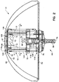
- Fig. 2 is a sectional view of the first surgical lighthead of Fig. 1, taken along line 2-2, showing a dome-shaped outer cover, a dome-shaped reflector surrounded by the outer cover, a lamp assembly surrounded by the reflector including a combination light and heat energy radiation filter apparatus with portions broken away to show a main light bulb and a redundant light bulb, and a handle assembly coupled to the lamp assembly;
- Fig. 3 is an enlarged view of a portion of Fig. 2 showing the lamp and handle assemblies;
- Fig. 4 is an exploded perspective view of the combination light and heat energy radiation filter apparatus of Fig. 2 illustrating eight rectangular filter plates and upper and lower plate-retaining assemblies;
- Fig. 5 is a top plan view taken along line 5-5 of Fig. 2, showing the combination light and heat energy filter apparatus including eight rectangular filter plates spaced apart in a pattern to define gaps between adjacent plates for flow of air therebetween;
- Fig. 6 is a top plan view similar to Fig. 5, showing light and heat radiation paths from the main light bulb toward the filter plates;
- Fig. 7 is a top plan view similar to Fig. 5, showing light and heat radiation paths from the redundant light bulb toward the filter plates; and
- Fig. 8 is a top plan view of an alternative embodiment combination light and heat energy filter apparatus according to the present invention including ten filter plates spaced apart in a pattern to define gaps between adjacent plates, and showing light and heat radiation paths from a main light bulb toward the filter plates.
- A
surgical light system 30 includes afirst arm assembly 32, asecond arm assembly 34, afirst lighthead 36 coupled tofirst arm assembly 32, and asecond lighthead 38 coupled tosecond arm assembly 34 as shown in Fig. 1. First andsecond arm assemblies ceiling 44. It is understood that first and second arm assemblies 32, 34 may be mounted to any suitable support such as a wall or separate stand. - Each
arm assembly first arm 46, a lower orsecond arm 48, and ayoke 50. Eachfirst arm 46 is independently pivotable relative to mounting apparatus 42 about avertical pivot axis 52. Eachsecond arm 48 is pivotable relative to the respectivefirst arm 46 about a respective horizontal ormain pivot axis 54 and about a respectivevertical pivot axis 53 that is spaced frompivot axis 52. In addition, eachyoke 50 is pivotable relative to the respectivesecond arm 48 about arespective pivot axis 56 and each oflightheads respective yoke 50 about arespective pivot axis 58. Thus,arm assemblies lightheads ceiling 44. - Each
lighthead shaped housing 60, alens 62 through which light shines from therespective lighthead handle assembly 64 as shown in Fig. 1. Eachhandle assembly 64 includes ahandle 66 which is grasped by a surgeon to move therespective lighthead arm assembly lighthead lighthead lighthead - Handle 66 of each
handle assembly 64 is rotatable to move the at least one light bulb relative to the reflector to adjust the pattern size of reflected light that illuminates the surgical site. The pattern size may be thought of generally as the diameter of the area illuminated by the associatedlighthead assembly 64 includes abutton 74 at the bottom ofhandle 66 which is pressed to adjust the intensity level at which light emanates from the at least one light bulb. Handleassembly 64 includes anescutcheon 76 abovehandle 66. Handleassembly 64 further includes a first set of LED's 78 and a second set of LED's 80 that are visible on respective sides ofescutcheon 76 to provide user information regarding the operation of the at least one light bulb and the intensity level at which light is emanating from the at least one light bulb. In preferred embodiments, each of the at least one light bulb is a tungsten halogen lamp. -
Surgical light system 30 includes acontroller box 82, shown in Fig. 1, which is mounted to awall 84 or other suitable structure and which is coupled electrically tosurgical lightheads Controller box 82 includes acontrol panel 86 havingbuttons 88 and sets of LED's 90 that are associated with eachrespective lighthead respective lighthead button 86 is pressed to change the light intensity of the at least one light bulb in the same manner thatbutton 74 of the associatedlighthead respective handle assembly 64 orcontroller box 82.Surgical light system 30 optionally may include a task light 92, shown in Fig. 1, andcontroller box 82 optionally may include abutton 94 that is pressed to turn task light 92 on and off. - Other features of surgical
light system 30 are discussed and shown in detail in co-pending patent applications Serial No. 09/050,530 entitled Support Arm for Surgical Light System; Serial No. 09/050,265 entitled Reflector for Surgical Light System; Serial No. 09/050,534 entitled Controls for Surgical Light System; and Serial No. 09/050,576 Task Light for Surgical Light System, all of which are hereby incorporated by reference. - Each
lighthead radiation filter apparatus 10 as shown in Figs. 2-7.Filter apparatus 10 is positioned withinhousing 60 and configured to encirclelight bulbs bulbs reflector 72 to be reflected towardslens 62 and out oflighthead Filter apparatus 10 illustratively includes a plurality ofrectangular filter plates 12 fabricated from specially formulated glass that filters the visible light to produce light of a desired color while absorbing most of the heat energy radiation radiated from either ofbulbs - Illustratively, the
filter plates 12 can be configured to block a predefined spectrum of heat energy radiation such as infrared radiation. In addition,filter plates 12 can be configured to filter visible light to remove a predefined spectrum of visible light. -
Filter plates 12 are retained between a pair of plate-receivingassemblies assembly 16 includes an annulartop cover plate 20, anannular bottom plate 22 having plate-receivingslots 23, and anannular gasket 21 configured to lie between top andbottom plates Gasket 21 provides a compressible cushion forfilter plates 12 when they are retained withinassembly 16 as explained below. Top andbottom plates screws 102. Upper plate-receivingassembly 16 is coupled toreflector 72 by fourscrews 106 and tohousing 60 by fourscrews 108 as shown in Figs. 2 and 3.Housing 60 includes a removabletop cover 61 to concealscrews 108. - Similar to upper plate-receiving
assembly 16, lower plate-receivingassembly 18 includes an annularbottom cover plate 24, an annulartop plate 26 having plate-receivingslots 27, and anannular gasket 25 configured to lie between bottom andtop plates Gasket 25 performs the same function asgasket 21 above. Lower plate-receiving assembly bottom andtop plates screws 104. -
Lightheads filter support assembly 110 that includes upper and lowerannular support plates spacers 113 as shown in Figs. 2-4. Upper and lower plate-receivingassemblies upper support plate 112 offilter support assembly 110 by fourrod assemblies 116. Eachrod assembly 116 includes arod 118 having an upper threadedend 120 and a lower threadedend 122, a filterplate spacing tube 124, a supportassembly spacing tube 126, andwashers 128 and nuts 130. The threaded ends 120 ofrods 118 extend throughapertures 131 found intop plate 20,gasket 21 andbottom plate 22 to permit attachment of thewashers 128 andnuts 130 to therods 118 as shown in Figs. 2 and 3. - Filter plate and support
assembly spacing tubes rod 118 can extend axially through them. Filterplate spacing tube 124 has an axial length to spacelower plate 22 of upper plate-receivingassembly 16 apart fromupper plate 26 of lower plate-receivingassembly 18 so thatfilter plates 12 are snugly received in plate-receivingslots gaskets filter plates 12. Supportassembly spacing tube 126 has an axial length defined by the distance betweenupper plate 112 offilter support assembly 110 andbottom cover plate 24 of lower plate-retainingassembly 18 whenfilter 10 is coupled tohousing 60 andreflector 72 as shown in Figs. 2 and 3.Washers 128 andnuts 130 are attached to upper and lower threaded ends 120, 122 ofrod 118 to securefilter apparatus 10 withinlighthead -
Filter support assembly 110 is coupled to thelens 62 by fasteners 140 which extend through mountingplate 142, throughplate 114 and into threadedspacers 113 as shown best in Fig. 3.Fasteners 144 extend throughplate 112 and into the other threaded end ofspacers 113. Therefore thefilter apparatus 10 is held in a desired location within an enclosure defined byhousing 60 andlens 62. - As
handle 66 is rotated,bulbs arrow 67 in Fig. 3. Details of the movement of bulbs are described in copending application Serial No. 09/050,534 entitled Controls for Surgical Light System referenced above. - In an illustrated embodiment of Figs. 2-7, eight
filter plates 12 are spaced apart in a generally octagonal pattern as best shown in Figs. 4-7, withgaps 14 betweenadjacent filter plates 12.Gaps 14 between thefilter plates 12 advantageously lower the thermal resistance offilter 10 by allowing for flow of air as shown byarrows 40 in Fig. 5. Thus, as air in the vicinity oflight bulbs filter plates 12 increases in temperature due to radiation of heat frombulbs filter plates 12, thegaps 14 permit convective airflow acrossfilter apparatus 10 to assist in dissipating heat withinlighthead 36. The prevention of localized heat buildup withinlighthead 36 results in improved operation, such as increased life expectancy forbulbs housing 60. As discussed below, the improved cooling permits the use of higher wattage bulbs to provide additional light and improve illumination at a surgical site while maintaining acceptable temperatures with the surgical light apparatus. - Although
lighthead housing 60 andlens 62, it is understood that convective airflow encouraged byfilter apparatus 10 will improve cooling irrespective of whether a lighthead is hermetically sealed, nominally sealed, or passageways for introduction of external air into the lighthead are provided. - The octagonal shape of Figs. 4-7 includes four
inner filter plates 12 spaced apart in a first square pattern and fourouter filter plates 12 spaced apart in a second square pattern spaced radially outward of the first square pattern, with the square patterns being rotationally offset by 45°. In this configuration, left and right side edges 13, 15 ofinner filter plates 12 are positioned radially inward of side edges 13, 15 of theouter filter plates 12. Optionally, each of the eightfilter plates 12 can be positioned in an alternative octagonal pattern so thatleft side edge 13 of eachfilter plate 12 is spaced apart and radially inward ofright side edge 15 of an adjacent filter plate. In this optional configuration, the eightfilter plates 12 are each positioned uniformly relative to a geometric center of the pattern of the octagonal pattern with a rotational offset of 45° between adjacent filter plates when viewed from the center of the pattern. - Main
light bulb 68 in preferred embodiments is positioned at the geometric center of the pattern offilter plates 12, as best shown in the octagonal pattern of Fig. 6.Filter plates 12 are sized so that left and right side edges 13, 15 of radiallyinward filter plates 12 block light and heat energy radiation from main light bulb 6& radiating toward left and right side edges 13, 15 of radially outward filter plates as illustrated byradiation lines 132. Thus,gaps 14 are obscured from a direct line of sight of radiation from mainlight bulb 68, and light and heat radiation is blocked over a 360° field of view looking radially outward from mainlight bulb 68. Similarly, as shown byradiation lines 134 in Fig. 7, left and right side edges 13, 15 of radiallyinward filter plates 12 block radiation fromredundant light bulb 70 radiating toward left and right side edges 13, 15 of radiallyoutward filter plates 12 to block heat energy radiation from the second light source over a 360° field of view looking radially outward fromredundant light bulb 70. -
Filter apparatus 10 according to the present invention provides improved cooling so that, for example, a sealedsurgical lighthead filter plates 12 configured to produce a filtered light color temperature of about 4200°K. Filter apparatus 10 provides for a total integrated spectral transmittance (filter lumen output divided by lamp lumen input) of at least about 64% and a maximum heat to light ratio (sum of visible, ultraviolet, and infrared energy divided by total footcandles) of about 3.8 µW/cm2-footcandle. Advantageously, this level of cooling is obtained without additional heat radiation filter elements on eitherreflector 72 orlens 62, such as a thin film coating that selectively filters visible light and heat energy radiation. Further advantageously, this level of cooling can be maintained for any orientation oflighthead lighthead acrylic lens 62 facing towardceiling 44 without causing any optical distortion of the lens. Furthermore advantageously, this level of cooling can be obtained using aaluminum reflector 72 having an opaque surface. - The
improved filter apparatus 10 of the present invention permitshigher wattage bulbs bulbs filter plates 12 is maintained at or below about 500° F (260°C) using thefilter apparatus 10. - An alternative embodiment filter apparatus 10' employing ten filter plates 12' arranged in a decahedron pattern is shown in Fig. 8. Similar to the embodiment of Figs. 2-7, left and right side edges 13', 15' of radially inward filter plates 12' block radiation from main and
redundant light bulbs bulbs - Thus, a light and heat energy radiation filter apparatus according to the present invention provides for improved cooling of a surgical lighthead by providing at least one gap within the filter element to allow convective airflow to enhance cooling of the lamps and filter elements. Providing gaps that are substantially obscured from a direct line of radiation from the light source while encouraging convective air flow past the filter provides for filtering substantially all light and heat energy radiation while reducing operating temperature.
- Although the preferred embodiments use geometric arrangements of generally rectangular plates having gaps between adjacent plates, gaps can be provided by other means such as gaps between curved filter elements or by a unitary filter element formed to include at least one gap.
Claims (24)
- An apparatus for use with a surgical light fixture having a first light source (68) and an enclosure (60) surrounding the first light source, the enclosure including a reflector (72) and a lens (62) transparent to visible light, characterized in that the apparatus is for cooling a surgical light fixture in which the reflector (72) is configured to reflect light from the first light source (68) towards the lens (62), the apparatus comprising a plurality of filter elements (12) coupled to the enclosure (60) between the first light source (68) and the reflector (72), the plurality of filter elements (12) being formed at least in part from material that is substantially transparent to visible light radiation and that substantially blocks transmission of heat energy radiation, and the plurality of filter elements (12) being configured to intersect substantially all radiation from the first light source (68) that otherwise would pass to the reflector (72) and through the lens (62), the plurality of filter elements (12) being configured to define at least one gap between two adjacent filter elements.
- The apparatus of claim 1 wherein the plurality of filter elements (12) are configured to provide a gap between each pair of adjacent filter elements.
- The apparatus of either claim 1 or claim 2 wherein the filter elements are rectangular filter plates (12).
- The apparatus of claim 3 wherein each filter plate (12) has substantially the same shape.
- The apparatus of either claim 3 or claim 4 wherein the plurality of filter plates (12) comprises a first plurality of filter plates arranged in a first pattern and a second plurality of filter plates arranged in a second pattern positioned radially outward of the first pattern.
- The apparatus of any one of claims 1 to 4 wherein the plurality of filter elements (12) includes a first set of filter plates and a second set of filter plates, the first set of filter plates being interleaved with the second set of filter plates so that each filter plate of the first set of filter plates is adjacent two filter plates of the second set of filter plates, and adjacent filter plates are separated by a gap.
- The apparatus of claim 6 wherein the first set of filter plates is arranged in a first pattern and the second set of filter plates is arranged in a second pattern spaced radially outward of the first set of filter plates.
- The apparatus of any one of claims 1 to 4 wherein the plurality of filter elements (12) comprises four inner filter plates spaced apart in a first square pattern and four outer filter plates spaced apart in a second square pattern located radially outward of the first square pattern and rotationally offset from the first square pattern by about 45°.
- The apparatus of claim 1 wherein the plurality of filter elements (12) comprises a plurality of filter plates, each filter plate having a front, a back, a first side edge, and a second side edge, the plurality of filter plates being arranged in a pattern around the light source (68) with the front of each filter plate facing toward the light source, the back of each filter plate facing away from the light source, and the first side edge of each filter plate being spaced apart from the second side edge of an adjacent filter plate and located radially inward toward the light source from the second side edge of the adjacent filter plate.
- The apparatus of any preceding claim wherein the filter elements (12) block a predefined spectrum of heat energy radiation.
- The apparatus of and preceding claim wherein the filter elements (12) are configured to block transmission of heat energy radiation from the first light source (68) to the reflector (72) substantially over a 360° field of view about a longitudinal axis through the first light source.
- A surgical light apparatus (36, 38) having a first light source (68) and an enclosure (60) surrounding the first light source (68) and including a reflector (72) and a lens (62) substantially transparent to visible light, the first light source generating visible light and heat energy radiation, the apparatus further comprising a cooling apparatus as claimed in any preceding claim.
- The apparatus of claim 12 further comprising a second light source (70) spaced apart from the first light source (68).
- The apparatus of claim 13 wherein the filter elements (12) configured to block heat energy radiation from the second light source (70) to the reflector (72) substantially over a 360° field of view about a longitudinal axis through the second light source, the axes through the first and second light sources being spaced apart and parallel.
- The apparatus of any one of claims 12 to 14 wherein the enclosure (60) is substantially sealed to prevent entry of air into the enclosure.
- The apparatus of claim 15 wherein the enclosure (60) is hermetically sealed.
- The apparatus of any one of claims 12 to 16 wherein lens (62) is substantially transparent to heat energy radiation.
- The apparatus of any one of claims 12 to 17 wherein the lens (62) is devoid of a coating that selectively passes visible light and that blocks heat energy radiation.
- The apparatus of any one of claims 12 to 18 wherein the lens (62) is an acrylic lens.
- The apparatus of any one of claims 12 to 19 wherein the reflector (72) is configured to reflect visible light and heat energy radiation toward the lens.
- The apparatus of any one of claims 12 to 20 wherein the reflector (72) is devoid of a coating that selectively filters visible light and heat energy radiation.
- The apparatus of any one of claims 12 to 21 wherein the reflector (72) includes an opaque surface.
- The apparatus of any one of claims 12 to 22 wherein the reflector (72) includes a surface formed from aluminum.
- The apparatus of any one of claims 12 to 23 wherein the heat energy radiation includes infrared radiation.
Applications Claiming Priority (5)
| Application Number | Priority Date | Filing Date | Title |
|---|---|---|---|
| US7966798P | 1998-03-27 | 1998-03-27 | |
| US79667P | 1998-03-27 | ||
| US09/050,529 US6443596B1 (en) | 1998-03-27 | 1998-03-30 | Surgical light apparatus with improved cooling |
| US50529 | 1998-03-30 | ||
| PCT/US1999/005920 WO1999050590A1 (en) | 1998-03-27 | 1999-03-19 | Surgical light apparatus with improved cooling |
Publications (3)
| Publication Number | Publication Date |
|---|---|
| EP1064494A1 EP1064494A1 (en) | 2001-01-03 |
| EP1064494B1 true EP1064494B1 (en) | 2006-11-29 |
| EP1064494B8 EP1064494B8 (en) | 2007-01-17 |
Family
ID=26728376
Family Applications (1)
| Application Number | Title | Priority Date | Filing Date |
|---|---|---|---|
| EP99912663A Expired - Lifetime EP1064494B8 (en) | 1998-03-27 | 1999-03-19 | Surgical light apparatus with improved cooling |
Country Status (10)
| Country | Link |
|---|---|
| US (2) | US6443596B1 (en) |
| EP (1) | EP1064494B8 (en) |
| JP (1) | JP4187414B2 (en) |
| AT (1) | ATE347070T1 (en) |
| AU (1) | AU3098799A (en) |
| BR (1) | BR9909112A (en) |
| CA (1) | CA2325532C (en) |
| DE (1) | DE69934216T2 (en) |
| TW (1) | TW490544B (en) |
| WO (1) | WO1999050590A1 (en) |
Families Citing this family (23)
| Publication number | Priority date | Publication date | Assignee | Title |
|---|---|---|---|---|
| US6443596B1 (en) * | 1998-03-27 | 2002-09-03 | Hill-Rom Services, Inc. | Surgical light apparatus with improved cooling |
| CA2395377C (en) * | 1999-12-23 | 2008-02-19 | Hill-Rom Services, Inc. | Surgical theater system |
| US7097145B2 (en) * | 2001-09-14 | 2006-08-29 | Hill-Rom Services, Inc. | Support arm for a surgical theater system |
| FR2851028B1 (en) * | 2003-02-06 | 2006-01-27 | Alm | LIGHTING DEVICE |
| US6908208B1 (en) | 2004-01-02 | 2005-06-21 | Raymond Quentin Hyde | Light to be worn on head |
| CA2521790A1 (en) * | 2004-09-30 | 2006-03-30 | Compx International Inc. | Support for flat monitors |
| DE102004055838B4 (en) * | 2004-11-19 | 2011-07-28 | Dräger Medical GmbH, 23558 | Operating light and control device |
| US8016470B2 (en) | 2007-10-05 | 2011-09-13 | Dental Equipment, Llc | LED-based dental exam lamp with variable chromaticity |
| US8459852B2 (en) * | 2007-10-05 | 2013-06-11 | Dental Equipment, Llc | LED-based dental exam lamp |
| DE202005007211U1 (en) * | 2005-05-06 | 2005-08-04 | Heine Optotechnik Gmbh & Co. Kg | lighting device |
| TWM287663U (en) * | 2005-05-10 | 2006-02-21 | Tusng-Chuan Liu | Microvideo on dental lamp equipment |
| DE102007011260A1 (en) * | 2007-03-06 | 2008-09-11 | Werner Quinten | lamp |
| DE102007042646A1 (en) * | 2007-09-10 | 2009-03-12 | Trilux Gmbh & Co. Kg | LED surgical light |
| DE102007045456A1 (en) * | 2007-09-24 | 2009-04-09 | Trumpf Kreuzer Medizin Systeme Gmbh + Co. Kg | Lighting device for a medical supply unit |
| US9207484B2 (en) | 2012-09-26 | 2015-12-08 | Apple Inc. | Computer LED bar and thermal architecture features |
| FR2999274A1 (en) * | 2012-12-07 | 2014-06-13 | Maquet Sas | LED LIGHTING DEVICE FOR OPERATIVE FIELDS COMPRISING A DIVIDER OF LIGHT BEAMS |
| DE102012025396A1 (en) | 2012-12-24 | 2014-06-26 | Dräger Medical GmbH | Illuminating device for illuminating a footprint |
| EP3206653B1 (en) * | 2014-10-17 | 2019-06-26 | Ondal Medical Systems GmbH | Assembly device with rotation coupling for a stand device |
| WO2016058706A1 (en) | 2014-10-17 | 2016-04-21 | Ondal Medical Systems Gmbh | Mounting device for a stand device, and mounting system with the mounting device |
| DE102016121689A1 (en) | 2016-11-11 | 2018-05-17 | Trilux Medical Gmbh & Co. Kg | Mono reflector lamp operating room |
| KR102139913B1 (en) * | 2018-03-15 | 2020-07-31 | 김효준 | LED astral lamp |
| EP4097514B1 (en) * | 2020-01-31 | 2024-03-20 | American Sterilizer Company | Light head with rotating lens assembly and method of operating same |
| EP4071406A1 (en) | 2021-04-09 | 2022-10-12 | TRUMPF Medizin Systeme GmbH + Co. KG | Yoke for a suspension system for a medical lamp, suspension system and system of a medical lamp body and a suspension system |
Family Cites Families (25)
| Publication number | Priority date | Publication date | Assignee | Title |
|---|---|---|---|---|
| US2002313A (en) * | 1934-12-24 | 1935-05-21 | Earl L Canfield | Lighting appliance |
| US2297781A (en) | 1940-06-24 | 1942-10-06 | John A Korengold | Lamp structure |
| US3075071A (en) | 1958-09-04 | 1963-01-22 | Ritter Co Inc | Sterilizable focusing means for surgical lights |
| GB927676A (en) | 1961-04-17 | 1963-05-29 | Gen Electric Co Ltd | Improvements in or relating to electric lighting fittings |
| US3588488A (en) | 1969-06-16 | 1971-06-28 | Sybron Corp | High kelvin surgical lighting fixture |
| US3609335A (en) | 1969-08-08 | 1971-09-28 | American Sterilizer Co | High intensity surgical light |
| US4032771A (en) | 1973-02-06 | 1977-06-28 | Original Hanau Quarzlampen Gmbh | Surgical operating lamp |
| US4037096A (en) | 1974-08-09 | 1977-07-19 | American Sterilizer Company | Illuminator apparatus using optical reflective methods |
| US4135231A (en) | 1977-05-10 | 1979-01-16 | American Sterilizer Company | Surgical light assembly |
| DE2725428C2 (en) | 1977-06-04 | 1983-12-01 | W.C. Heraeus Gmbh, 6450 Hanau | Housing of an operating light |
| US4254455A (en) | 1979-12-21 | 1981-03-03 | Pelton & Crane Company | Reflector for dental, medical or the like lighting device |
| US4254454A (en) | 1979-12-21 | 1981-03-03 | Pelton & Crane Company | Self-ventilating dental lighting device |
| EP0203541B1 (en) | 1985-05-25 | 1991-02-27 | Green Cross Corporation | Therapeutic and prophylactic agents for peptic ulcer, compounds contained therein and processes for their production |
| GB8726664D0 (en) | 1987-11-13 | 1987-12-16 | Holroyd Associates Ltd | Flexible reinforced polymeric material |
| DE68925792T2 (en) | 1988-12-12 | 1996-07-25 | Konishiroku Photo Ind | Magnetic record carrier |
| US5057698A (en) | 1989-11-13 | 1991-10-15 | Exide Electronics | Shunt circuit for reducing audible noise at low loading conditions of a power supply employing a high frequency resonant converter |
| US5099405A (en) | 1990-03-16 | 1992-03-24 | American Sterilizer Company | Lamp change mechanism |
| US5067064A (en) | 1990-03-16 | 1991-11-19 | American Sterilizer Company | Pattern change mechanism |
| DE9017143U1 (en) * | 1990-12-19 | 1991-03-07 | Delma, Elektro- Und Medizinische Apparatebaugesellschaft Mbh, 7200 Tuttlingen | Operating light |
| US5072349A (en) | 1991-04-03 | 1991-12-10 | Howard Waniga | Lighting device for surgical and medical uses |
| EP0591386B1 (en) | 1991-06-25 | 1998-11-25 | Alm | Medical device for lighting a treatment field |
| DE4140325C2 (en) * | 1991-12-06 | 2003-07-31 | Delma Elektro Med App | surgical light |
| DE4225303A1 (en) * | 1992-07-31 | 1994-02-03 | Bosch Gmbh Robert | Automobile headlamp unit - uses gas discharge lamp enclosed by glass cylinder sealed at front end and vented at rear end. |
| DE19621853A1 (en) | 1996-05-31 | 1997-12-04 | Heraeus Med Gmbh | Method of irradiating an illumination field esp. using medical light with incandescent lamp e.g. for dentistry |
| US6443596B1 (en) * | 1998-03-27 | 2002-09-03 | Hill-Rom Services, Inc. | Surgical light apparatus with improved cooling |
-
1998
- 1998-03-30 US US09/050,529 patent/US6443596B1/en not_active Expired - Fee Related
-
1999
- 1999-03-19 AT AT99912663T patent/ATE347070T1/en not_active IP Right Cessation
- 1999-03-19 DE DE69934216T patent/DE69934216T2/en not_active Expired - Lifetime
- 1999-03-19 CA CA002325532A patent/CA2325532C/en not_active Expired - Fee Related
- 1999-03-19 WO PCT/US1999/005920 patent/WO1999050590A1/en not_active Ceased
- 1999-03-19 EP EP99912663A patent/EP1064494B8/en not_active Expired - Lifetime
- 1999-03-19 JP JP2000541456A patent/JP4187414B2/en not_active Expired - Lifetime
- 1999-03-19 AU AU30987/99A patent/AU3098799A/en not_active Abandoned
- 1999-03-19 BR BR9909112-7A patent/BR9909112A/en not_active IP Right Cessation
- 1999-03-26 TW TW088104845A patent/TW490544B/en not_active IP Right Cessation
-
2002
- 2002-07-02 US US10/188,439 patent/US6893137B2/en not_active Expired - Fee Related
Also Published As
| Publication number | Publication date |
|---|---|
| ATE347070T1 (en) | 2006-12-15 |
| DE69934216D1 (en) | 2007-01-11 |
| US6893137B2 (en) | 2005-05-17 |
| EP1064494B8 (en) | 2007-01-17 |
| WO1999050590A1 (en) | 1999-10-07 |
| JP2002510133A (en) | 2002-04-02 |
| CA2325532C (en) | 2004-11-02 |
| JP4187414B2 (en) | 2008-11-26 |
| AU3098799A (en) | 1999-10-18 |
| US6443596B1 (en) | 2002-09-03 |
| CA2325532A1 (en) | 1999-10-07 |
| DE69934216T2 (en) | 2007-03-29 |
| TW490544B (en) | 2002-06-11 |
| EP1064494A1 (en) | 2001-01-03 |
| US20020172033A1 (en) | 2002-11-21 |
| BR9909112A (en) | 2000-12-12 |
Similar Documents
| Publication | Publication Date | Title |
|---|---|---|
| EP1064494B8 (en) | Surgical light apparatus with improved cooling | |
| US4135231A (en) | Surgical light assembly | |
| US6132062A (en) | Task light for a surgical light apparatus | |
| US10386055B2 (en) | LED-based dental exam lamp | |
| US5743632A (en) | Thermally controlled light fixture | |
| US5537301A (en) | Fluorescent lamp heat-dissipating apparatus | |
| US5091835A (en) | High intensity lamp with improved air flow ventilation | |
| JP4386782B2 (en) | Lighting apparatus having a reflector | |
| US5367444A (en) | Thermal management techniques for lighting instruments | |
| US5473524A (en) | Field of action light for medical, particularly dental practice | |
| US5055697A (en) | Infrared radiator | |
| US20060245173A1 (en) | LED-powered dental operatory light | |
| US6793349B2 (en) | Image projector for use with luminaires | |
| JPS63108602A (en) | Spot light | |
| JP2022079196A (en) | Lighting equipment | |
| US20090168423A1 (en) | Energy-saving recessed tracklight system | |
| EP0586049B1 (en) | Thermal management techniques for lighting instruments | |
| JP3597480B2 (en) | Surgical surgical light with illuminator having discharge lamp | |
| JP2589001Y2 (en) | Lighting equipment for vanity cabinets | |
| CA1099682A (en) | Surgical light assembly with heat sink cooling | |
| RU2079773C1 (en) | Lighting fitting | |
| JPS63294714A (en) | plant cultivation equipment | |
| WO2002103238A1 (en) | Lamp and shade | |
| KR910000242Y1 (en) | Microscope | |
| JPH06267667A (en) | Variable light color type lighting system |
Legal Events
| Date | Code | Title | Description |
|---|---|---|---|
| PUAI | Public reference made under article 153(3) epc to a published international application that has entered the european phase |
Free format text: ORIGINAL CODE: 0009012 |
|
| 17P | Request for examination filed |
Effective date: 20001004 |
|
| AK | Designated contracting states |
Kind code of ref document: A1 Designated state(s): AT CH DE ES FR GB IT LI NL |
|
| RIN1 | Information on inventor provided before grant (corrected) |
Inventor name: TAFT, MICHAEL, A. C/O HILL-ROM,INC Inventor name: YEANEY, GERALD, L. Inventor name: BULKO, JOHN, M. |
|
| 17Q | First examination report despatched |
Effective date: 20041109 |
|
| GRAP | Despatch of communication of intention to grant a patent |
Free format text: ORIGINAL CODE: EPIDOSNIGR1 |
|
| RIC1 | Information provided on ipc code assigned before grant |
Ipc: F21V 29/00 20060101ALI20060623BHEP Ipc: F21V 9/04 20060101ALI20060623BHEP Ipc: F21S 8/00 20060101AFI20060623BHEP |
|
| GRAS | Grant fee paid |
Free format text: ORIGINAL CODE: EPIDOSNIGR3 |
|
| GRAA | (expected) grant |
Free format text: ORIGINAL CODE: 0009210 |
|
| AK | Designated contracting states |
Kind code of ref document: B1 Designated state(s): AT CH DE ES FR GB IT LI NL |
|
| PG25 | Lapsed in a contracting state [announced via postgrant information from national office to epo] |
Ref country code: NL Free format text: LAPSE BECAUSE OF FAILURE TO SUBMIT A TRANSLATION OF THE DESCRIPTION OR TO PAY THE FEE WITHIN THE PRESCRIBED TIME-LIMIT Effective date: 20061129 Ref country code: LI Free format text: LAPSE BECAUSE OF FAILURE TO SUBMIT A TRANSLATION OF THE DESCRIPTION OR TO PAY THE FEE WITHIN THE PRESCRIBED TIME-LIMIT Effective date: 20061129 Ref country code: IT Free format text: LAPSE BECAUSE OF FAILURE TO SUBMIT A TRANSLATION OF THE DESCRIPTION OR TO PAY THE FEE WITHIN THE PRESCRIBED TIME-LIMIT;WARNING: LAPSES OF ITALIAN PATENTS WITH EFFECTIVE DATE BEFORE 2007 MAY HAVE OCCURRED AT ANY TIME BEFORE 2007. THE CORRECT EFFECTIVE DATE MAY BE DIFFERENT FROM THE ONE RECORDED. Effective date: 20061129 Ref country code: CH Free format text: LAPSE BECAUSE OF FAILURE TO SUBMIT A TRANSLATION OF THE DESCRIPTION OR TO PAY THE FEE WITHIN THE PRESCRIBED TIME-LIMIT Effective date: 20061129 Ref country code: AT Free format text: LAPSE BECAUSE OF FAILURE TO SUBMIT A TRANSLATION OF THE DESCRIPTION OR TO PAY THE FEE WITHIN THE PRESCRIBED TIME-LIMIT Effective date: 20061129 |
|
| REG | Reference to a national code |
Ref country code: GB Ref legal event code: FG4D |
|
| RAP2 | Party data changed (patent owner data changed or rights of a patent transferred) |
Owner name: HILL-ROM SERVICES, INC. |
|
| REG | Reference to a national code |
Ref country code: CH Ref legal event code: EP |
|
| REF | Corresponds to: |
Ref document number: 69934216 Country of ref document: DE Date of ref document: 20070111 Kind code of ref document: P |
|
| NLT2 | Nl: modifications (of names), taken from the european patent patent bulletin |
Owner name: HILL-ROM SERVICES, INC. Effective date: 20061213 |
|
| PG25 | Lapsed in a contracting state [announced via postgrant information from national office to epo] |
Ref country code: ES Free format text: LAPSE BECAUSE OF FAILURE TO SUBMIT A TRANSLATION OF THE DESCRIPTION OR TO PAY THE FEE WITHIN THE PRESCRIBED TIME-LIMIT Effective date: 20070312 |
|
| ET | Fr: translation filed | ||
| NLV1 | Nl: lapsed or annulled due to failure to fulfill the requirements of art. 29p and 29m of the patents act | ||
| REG | Reference to a national code |
Ref country code: CH Ref legal event code: PL |
|
| PLBE | No opposition filed within time limit |
Free format text: ORIGINAL CODE: 0009261 |
|
| STAA | Information on the status of an ep patent application or granted ep patent |
Free format text: STATUS: NO OPPOSITION FILED WITHIN TIME LIMIT |
|
| 26N | No opposition filed |
Effective date: 20070830 |
|
| PGFP | Annual fee paid to national office [announced via postgrant information from national office to epo] |
Ref country code: FR Payment date: 20120319 Year of fee payment: 14 |
|
| PGFP | Annual fee paid to national office [announced via postgrant information from national office to epo] |
Ref country code: GB Payment date: 20120314 Year of fee payment: 14 |
|
| PGFP | Annual fee paid to national office [announced via postgrant information from national office to epo] |
Ref country code: DE Payment date: 20120411 Year of fee payment: 14 |
|
| GBPC | Gb: european patent ceased through non-payment of renewal fee |
Effective date: 20130319 |
|
| REG | Reference to a national code |
Ref country code: FR Ref legal event code: ST Effective date: 20131129 |
|
| REG | Reference to a national code |
Ref country code: DE Ref legal event code: R119 Ref document number: 69934216 Country of ref document: DE Effective date: 20131001 |
|
| PG25 | Lapsed in a contracting state [announced via postgrant information from national office to epo] |
Ref country code: FR Free format text: LAPSE BECAUSE OF NON-PAYMENT OF DUE FEES Effective date: 20130402 Ref country code: GB Free format text: LAPSE BECAUSE OF NON-PAYMENT OF DUE FEES Effective date: 20130319 Ref country code: DE Free format text: LAPSE BECAUSE OF NON-PAYMENT OF DUE FEES Effective date: 20131001 |