EP1064198B1 - Robust singularity avoidance in satellite attitude control - Google Patents
Robust singularity avoidance in satellite attitude control Download PDFInfo
- Publication number
- EP1064198B1 EP1064198B1 EP99916131A EP99916131A EP1064198B1 EP 1064198 B1 EP1064198 B1 EP 1064198B1 EP 99916131 A EP99916131 A EP 99916131A EP 99916131 A EP99916131 A EP 99916131A EP 1064198 B1 EP1064198 B1 EP 1064198B1
- Authority
- EP
- European Patent Office
- Prior art keywords
- signal
- attitude
- control
- satellite
- satellite attitude
- Prior art date
- Legal status (The legal status is an assumption and is not a legal conclusion. Google has not performed a legal analysis and makes no representation as to the accuracy of the status listed.)
- Expired - Lifetime
Links
Images

Classifications
-
- B—PERFORMING OPERATIONS; TRANSPORTING
- B25—HAND TOOLS; PORTABLE POWER-DRIVEN TOOLS; MANIPULATORS
- B25J—MANIPULATORS; CHAMBERS PROVIDED WITH MANIPULATION DEVICES
- B25J9/00—Program-controlled manipulators
- B25J9/16—Program controls
- B25J9/1602—Program controls characterised by the control system, structure, architecture
- B25J9/1607—Calculation of inertia, jacobian matrixes and inverses
-
- B—PERFORMING OPERATIONS; TRANSPORTING
- B64—AIRCRAFT; AVIATION; COSMONAUTICS
- B64G—COSMONAUTICS; VEHICLES OR EQUIPMENT THEREFOR
- B64G1/00—Cosmonautic vehicles
- B64G1/22—Parts of, or equipment specially adapted for fitting in or to, cosmonautic vehicles
- B64G1/24—Guiding or controlling apparatus, e.g. for attitude control
- B64G1/28—Guiding or controlling apparatus, e.g. for attitude control using inertia or gyro effect
- B64G1/286—Guiding or controlling apparatus, e.g. for attitude control using inertia or gyro effect using control momentum gyroscopes (CMGs)
-
- B—PERFORMING OPERATIONS; TRANSPORTING
- B64—AIRCRAFT; AVIATION; COSMONAUTICS
- B64G—COSMONAUTICS; VEHICLES OR EQUIPMENT THEREFOR
- B64G1/00—Cosmonautic vehicles
- B64G1/22—Parts of, or equipment specially adapted for fitting in or to, cosmonautic vehicles
- B64G1/24—Guiding or controlling apparatus, e.g. for attitude control
- B64G1/36—Guiding or controlling apparatus, e.g. for attitude control using sensors, e.g. sun-sensors, horizon sensors
Definitions
- This invention relates to satellites and robotic systems, for example controlling the orientation of a satellite using a plurality of control moment gyros (CMG).
- CMG control moment gyros
- attitude of an agile spacecraft or satellite is often maintained and adjusted with a control moment gyro array because those devices provide high torque and torque amplification.
- a typical CMG is a rotating mass suspended on a gimbal with an actuator to rotate it on the gimbal axis, producing torque and accumulating angular momentum.
- Angular momentum is the integral of torque over time.
- An array of n >3 CMGs is often used, allowing attitude control with some redundancy.
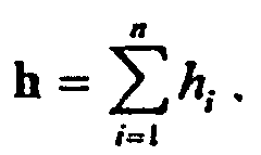
- Each CMG has an angular momentum ( h ) constrained essentially to a plane, the angular momentum vector of the gyro is nearly orthogonal to the gimbal axis.
- the error in orthogonality is small enough that it does not affect the operation of the CMG, the array of CMGs, or the attitude control of the satellite.
- the wheel speed of the CMG is essentially constant in most applications, but does not have to be for this invention to work.
- the attitude control calculates the desired attitude acceleration for the satellite ⁇ ⁇ c , being the three axis attitude accelerations.
- the present invention provides a satellite attitude control as defined in Claim 1.
- An object of the present invention is to significantly increase the speed in reorienting a satellite between two objects by utilizing more of the available angular momentum from the CMGs.
- the gimbal angle rates are calculated using a new pseudo inverse.
- the new pseudo inverse prevents the control from becoming unstable when the matrix generated by the Jacobean of the angular momentum with respect to the gimbal angles rank drops to two. Also if a singularity, the rank of the Jacobean drop from three to two, is encountered the solution trajectory passes through the singularity instead of getting caught in the singularity.
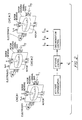
- Fig. 1 shows function blocks that may be implemented through hardware or software, preferably the latter in a computer based satellite control containing one or more signal processors programmed to produce output signals to control CMGs on the satellite as explained hereafter. Fundamentally the process is shown for a single signal path between two points, but it should be understood that single lines represent vector data which is 3 dimensional for the satellite attitude, attitude rate and torque, and n dimensional for the signals related to the n CMGs.
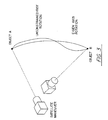
- the control scheme shown in Fig. 1 is used to pan or rotate the satellite on its axis from the line of sight view of an object A to a line of sight view of object B Fig 3.
- a typical closed loop control follows an eigen axis rotation path "old" by controlling the CMGs based on the actual (determined from the attitude determination system ADS in Fig. 3) and desired path attitude.
- the invention is not constrained to follow an eigen axis path as will be explained.
- the desired satellite attitude at input 10 presented as Euler angles, quatemions, Gibbs parameters, or some other convenient way of describing the attitude of a satellite, compared at 14 with actual attitude at input 12 generated by the Inertial Measurement Unit (IMU) 56 or some other method for determining satellite attitude.
- the attitude error 16 is used by the attitude control 18 to generate a desired body acceleration, ⁇ ⁇ c at output 20.
- the added term k I is to keep the equation from becoming indeterminate as the solution trajectory passes through internal singularities, that would be inescapable if this control was not used.
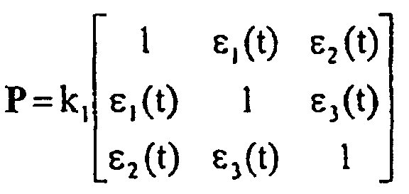
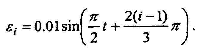
- the weighting matrix P is used to escape any singularity that is encountered. In order to do this P needs to be of the form where k 1 was equal to 1 in the proof of concept, and The time varying off diagonal terms in P provide the escape of a control trajectory even when it is started a Moore-Penrose elliptical singularity.
- the CMG array 48 responds to the gimbal rate command 42.
- the CMG array 48 movement produces torque h ⁇ 50 on the satellite 52.
- the satellite motion ⁇ 54 is detected by the attitude sensors 56.
- the invention has been explained in the context of a satellite control, but it can be used in systems, such as robotic systems, which can encounter singularities. With the benefit of the previous discussion of the invention, one of ordinary skill in the art may be able to modify the invention and the components and functions that have been described in whole or in part without departing from the true scope of the invention.
Landscapes
- Engineering & Computer Science (AREA)
- Remote Sensing (AREA)
- Chemical & Material Sciences (AREA)
- Combustion & Propulsion (AREA)
- Radar, Positioning & Navigation (AREA)
- Aviation & Aerospace Engineering (AREA)
- Physics & Mathematics (AREA)
- Mathematical Physics (AREA)
- Automation & Control Theory (AREA)
- Robotics (AREA)
- Mechanical Engineering (AREA)
- Control Of Position, Course, Altitude, Or Attitude Of Moving Bodies (AREA)
Description
δ ˙c = AT (PAAT + kI)-1 P h ˙c 36. The added term kI is to keep the equation from becoming indeterminate as the solution trajectory passes through internal singularities, that would be inescapable if this control was not used. The weighting matrix P is used to escape any singularity that is encountered. In order to do this P needs to be of the form

The invention has been explained in the context of a satellite control, but it can be used in systems, such as robotic systems, which can encounter singularities. With the benefit of the previous discussion of the invention, one of ordinary skill in the art may be able to modify the invention and the components and functions that have been described in whole or in part without departing from the true scope of the invention.
Claims (1)
- A satellite attitude control comprising a plurality of control moment gyros in an array (48) and a controller for changing a gimbal angle on each gyro, the controller comprising signal processing means comprising:characterised in thatmeans for receiving a desired satellite attitude signal (10);means (56) for producing an actual satellite attitude signal (12);means (14) for producing an attitude error signal (16) from the desired satellite attitude signal and the actual satellite attitude signal;means (18, 22) for producing a torque command signal (24) in response to the attitude error signal;means for producing an angular rate signal (42) for each gyro using a pseudo inverse control law (36) that uses said torque command signal and a Jacobean value for the angle of the gyro, said pseudo inverse including a term that prevents a singularity in the angular rate signal; andmeans for rotating a gyro in the array in response to the angular rate signal;
said pseudo inverse includes a term which prevents it from being indeterminant; and
said pseudo inverse is AT (PAAT + kI)-1 P, where A is the Jacobean value of the CMG array and P is a weighting matrix of the formwhere k1 is a constant and
Applications Claiming Priority (3)
| Application Number | Priority Date | Filing Date | Title |
|---|---|---|---|
| US09/039,959 US6039290A (en) | 1998-03-16 | 1998-03-16 | Robust singularity avoidance in satellite attitude control |
| US39959 | 1998-03-16 | ||
| PCT/US1999/005599 WO1999047419A1 (en) | 1998-03-16 | 1999-03-16 | Robust singularity avoidance in satellite attitude control |
Publications (2)
| Publication Number | Publication Date |
|---|---|
| EP1064198A1 EP1064198A1 (en) | 2001-01-03 |
| EP1064198B1 true EP1064198B1 (en) | 2004-11-10 |
Family
ID=21908307
Family Applications (1)
| Application Number | Title | Priority Date | Filing Date |
|---|---|---|---|
| EP99916131A Expired - Lifetime EP1064198B1 (en) | 1998-03-16 | 1999-03-16 | Robust singularity avoidance in satellite attitude control |
Country Status (5)
| Country | Link |
|---|---|
| US (1) | US6039290A (en) |
| EP (1) | EP1064198B1 (en) |
| JP (1) | JP4276381B2 (en) |
| DE (1) | DE69921790T2 (en) |
| WO (1) | WO1999047419A1 (en) |
Families Citing this family (39)
| Publication number | Priority date | Publication date | Assignee | Title |
|---|---|---|---|---|
| FR2786283B1 (en) * | 1998-11-19 | 2001-01-26 | Matra Marconi Space France | METHOD AND DEVICE FOR CONTROLLING THE ATTITUDE OF A SATELLITE |
| US6456901B1 (en) | 2001-04-20 | 2002-09-24 | Univ Michigan | Hybrid robot motion task level control system |
| DE10146159A1 (en) | 2001-09-19 | 2003-04-10 | Bionorica Ag | Use of extracts from Cimicifuga species as an organ-selective drug for the treatment of sex hormone-dependent diseases of the urogenital tract |
| US6732977B1 (en) | 2002-02-11 | 2004-05-11 | Lockheed Martin Corporation | System for on-orbit correction of spacecraft payload pointing errors |
| US6695263B1 (en) | 2002-02-12 | 2004-02-24 | Lockheed Martin Corporation | System for geosynchronous spacecraft rapid earth reacquisition |
| US7051980B2 (en) * | 2002-02-26 | 2006-05-30 | Lockheed Martin Corporation | Efficient orbit sparing system for space vehicle constellations |
| US6891498B2 (en) | 2002-03-28 | 2005-05-10 | Honeywell International Inc. | Inertial reference system for a spacecraft |
| US6702234B1 (en) * | 2002-03-29 | 2004-03-09 | Lockheed Martin Corporation | Fault tolerant attitude control system for zero momentum spacecraft |
| US6681649B2 (en) * | 2002-04-03 | 2004-01-27 | Honeywell International Inc. | Inertial control and measurement system |
| US6682019B2 (en) | 2002-04-04 | 2004-01-27 | Honeywell International Inc. | Minimum energy wheel configurations for energy storage and attitude control |
| US6648274B1 (en) | 2002-04-12 | 2003-11-18 | David A. Bailey | Virtual reaction wheel array |
| AU2003294218A1 (en) | 2002-08-28 | 2004-04-23 | Arizona Board Of Regents | Steering logic for control moment gyro system |
| US7561947B2 (en) * | 2003-10-06 | 2009-07-14 | Honeywell International Inc. | Dynamic CMG array and method |
| US7185855B2 (en) * | 2004-04-30 | 2007-03-06 | Honeywell International, Inc. | Method and system for steering a momentum control system |
| US7246776B2 (en) * | 2004-07-23 | 2007-07-24 | Honeywell International, Inc. | Method and system for CMG array singularity avoidance |
| US7014150B2 (en) * | 2004-07-30 | 2006-03-21 | Honeywell International Inc. | Method and system for optimizing torque in a CMG array |
| US7364120B2 (en) * | 2004-08-26 | 2008-04-29 | Honeywell International, Inc. | Quantized control-moment gyroscope array |
| US7464899B2 (en) * | 2005-08-03 | 2008-12-16 | Honeywell International Inc. | Method and system for determining a singularity free momentum path |
| US7370833B2 (en) * | 2005-10-20 | 2008-05-13 | Honeywell International Inc. | Method and system for determining a singularity free momentum path |
| US7693619B2 (en) * | 2005-11-30 | 2010-04-06 | Honeywell International Inc. | Method and system for controlling sets of collinear control moment gyroscopes with offset determination without attitude trajectory of spacecraft |
| US7835826B1 (en) | 2005-12-13 | 2010-11-16 | Lockheed Martin Corporation | Attitude determination system for yaw-steering spacecraft |
| US7805226B2 (en) * | 2006-09-29 | 2010-09-28 | Honeywell International Inc. | Hierarchical strategy for singularity avoidance in arrays of control moment gyroscopes |
| US7627404B2 (en) * | 2007-04-13 | 2009-12-01 | The Boeing Company | Singularity escape and avoidance using a virtual array rotation |
| JP5228641B2 (en) * | 2008-06-16 | 2013-07-03 | 三菱電機株式会社 | Attitude control device and position control device |
| JP5126107B2 (en) * | 2009-02-19 | 2013-01-23 | 三菱電機株式会社 | Satellite attitude control device |
| US9199746B2 (en) * | 2009-05-19 | 2015-12-01 | University Of Florida Research Foundation, Inc. | Attitude control system for small satellites |
| JP5556782B2 (en) * | 2011-10-04 | 2014-07-23 | 三菱電機株式会社 | Satellite attitude control device |
| US10252151B2 (en) | 2012-03-15 | 2019-04-09 | Motorika Limited | Gyroscopic apparatuses and methods of using same |
| US9038958B1 (en) | 2012-05-29 | 2015-05-26 | United States Of America As Represented By The Secretary Of The Navy | Method and apparatus for contingency guidance of a CMG-actuated spacecraft |
| US9061775B2 (en) | 2012-06-22 | 2015-06-23 | Isaac M. Ross | Method and apparatus for spacecraft attitude control using polynomial interpolation |
| US8880246B1 (en) | 2012-08-22 | 2014-11-04 | United States Of America As Represented By The Secretary Of The Navy | Method and apparatus for determining spacecraft maneuvers |
| US9567112B1 (en) | 2013-06-27 | 2017-02-14 | The United States Of America, As Represented By The Secretary Of The Navy | Method and apparatus for singularity avoidance for control moment gyroscope (CMG) systems without using null motion |
| CN104238563B (en) * | 2014-09-04 | 2017-01-18 | 北京航空航天大学 | Design method of control moment gyroscopes with surface inclination angles changeable |
| US10737770B2 (en) * | 2015-02-23 | 2020-08-11 | Arif Mir Jalal ogly PASHAYEV | Method and device for increasing the stability and maneuverability of unmanned aerial vehicles (UAV) using a gyroscopic effect |
| CN106767673B (en) * | 2016-11-29 | 2019-06-21 | 上海卫星工程研究所 | Pointing measurement method for high-precision optical sensitive load of satellite |
| CN110466806B (en) * | 2019-07-24 | 2020-09-18 | 北京控制工程研究所 | A Method of Using CMG to Control Satellite Attitude |
| CN111897355B (en) * | 2020-08-06 | 2022-09-13 | 中国科学院微小卫星创新研究院 | Satellite attitude maneuver trajectory planning method |
| US12617554B2 (en) | 2023-03-08 | 2026-05-05 | The Boeing Company | Systems and methods for combined control moment gyroscope and thruster control |
| CN116834976B (en) * | 2023-06-07 | 2025-09-19 | 北京理工大学 | Fault-tolerant control distribution method for RCS moment output at initial stage of reentry section of aerospace vehicle |
Family Cites Families (13)
| Publication number | Priority date | Publication date | Assignee | Title |
|---|---|---|---|---|
| US3741500A (en) * | 1971-04-21 | 1973-06-26 | Sperry Rand Corp | A cmg fine attitude control system |
| FR2566935B1 (en) * | 1984-06-27 | 1986-12-12 | Commissariat Energie Atomique | OPTIMIZED CONTROL SYSTEM FOR MOVEMENTS OF A SENSITIVE AND ACTIVE MOBILE WITH RESPECT TO A PASSIVE LOCAL ENVIRONMENT USING LOCAL PROXIMETRIC SENSORS |
| US4860215A (en) * | 1987-04-06 | 1989-08-22 | California Institute Of Technology | Method and apparatus for adaptive force and position control of manipulators |
| US5159249A (en) * | 1989-05-16 | 1992-10-27 | Dalila Megherbi | Method and apparatus for controlling robot motion at and near singularities and for robot mechanical design |
| US4967126A (en) * | 1990-01-30 | 1990-10-30 | Ford Aerospace Corporation | Method of controlling a seven degree of freedom manipulator arm |
| US5276390A (en) * | 1991-10-04 | 1994-01-04 | Hewlett-Packard Company | System for hybrid position and force control |
| US5777580A (en) * | 1992-11-18 | 1998-07-07 | Trimble Navigation Limited | Vehicle location system |
| US5441222A (en) * | 1993-04-26 | 1995-08-15 | Hughes Aircraft Company | Attitude control of spinning spacecraft |
| US5628267A (en) * | 1993-11-01 | 1997-05-13 | Mitsubishi Jukogyo Kabushiki Kaisha | Oscillation suppression device and ship provided with the same |
| US5681012A (en) * | 1995-01-05 | 1997-10-28 | Hughes Electronics | Spacecraft control with skewed control moment gyros |
| US5692707A (en) * | 1995-05-15 | 1997-12-02 | Hughes Aircraft Company | Universal spacecraft attitude steering control system |
| US5794892A (en) * | 1995-10-25 | 1998-08-18 | Hughes Electronics | Critical nutation dampling on spinning bodies via momentum wheels or similar devices |
| US5765780A (en) * | 1995-12-22 | 1998-06-16 | Hughes Electronics Corporation | Systematic vectored thrust calibration method for satellite momentum control |
-
1998
- 1998-03-16 US US09/039,959 patent/US6039290A/en not_active Expired - Fee Related
-
1999
- 1999-03-16 EP EP99916131A patent/EP1064198B1/en not_active Expired - Lifetime
- 1999-03-16 DE DE69921790T patent/DE69921790T2/en not_active Expired - Lifetime
- 1999-03-16 WO PCT/US1999/005599 patent/WO1999047419A1/en not_active Ceased
- 1999-03-16 JP JP2000536622A patent/JP4276381B2/en not_active Expired - Fee Related
Also Published As
| Publication number | Publication date |
|---|---|
| JP4276381B2 (en) | 2009-06-10 |
| DE69921790T2 (en) | 2005-11-03 |
| JP2002506773A (en) | 2002-03-05 |
| DE69921790D1 (en) | 2004-12-16 |
| US6039290A (en) | 2000-03-21 |
| WO1999047419A1 (en) | 1999-09-23 |
| EP1064198A1 (en) | 2001-01-03 |
Similar Documents
| Publication | Publication Date | Title |
|---|---|---|
| US6039290A (en) | Robust singularity avoidance in satellite attitude control | |
| US6131056A (en) | Continuous attitude control that avoids CMG array singularities | |
| EP1064196B1 (en) | Singularity avoidance in a cmg satellite attitude control | |
| CA2041857C (en) | Attitude control system for momentum-biased spacecraft | |
| EP1064197B1 (en) | Cmg control based on angular momentum to control satellite attitude | |
| Schaub et al. | Feedback control law for variable speed control moment gyros | |
| US6154691A (en) | Orienting a satellite with controlled momentum gyros | |
| JP4307247B2 (en) | Method and apparatus for controlling and steering the attitude of an artificial satellite by a gyrodyne cluster | |
| US8113468B2 (en) | Precision attitude control system for gimbaled thruster | |
| US6917862B2 (en) | Singularity escape/avoidance steering logic for control moment gyro systems | |
| US6360996B1 (en) | Steering control for skewed scissors pair CMG clusters | |
| JP2004535324A5 (en) | ||
| US20080035797A1 (en) | Method of Controlling the Attitude of Satellites, Particularly Agile Satellites with a Reduced Number of Gyrodynes | |
| Caccavale et al. | Quaternion-based kinematic control of redundant spacecraft/manipulator systems | |
| JP2003521424A (en) | Systems and methods for controlling spacecraft attitude | |
| EP0790542A3 (en) | Method for controlling the attitude of a three-axis stabilized, earth oriented bias momentum spacecraft | |
| KR19990063535A (en) | DEVICE AND METHOD FOR CONTROLLING MOVING OBJECT | |
| JP2007033401A (en) | Antenna control device for satellite tracking | |
| Lappas et al. | Combined Singularity Avoidance for Redundant Control Moment Gyro (CMG) Clusters | |
| JPS6138076B2 (en) | ||
| Orsag et al. | Sensors and Control | |
| Corke | Advanced Visual Servoing | |
| Song et al. | Robust Control of the Missile Attitude Based on Quaternion Feedback | |
| Ham et al. | Computer graphic animation for helicopter control | |
| Schallig et al. | Maximum null motion algorithm for single gimbal control moment gyroscopes |
Legal Events
| Date | Code | Title | Description |
|---|---|---|---|
| PUAI | Public reference made under article 153(3) epc to a published international application that has entered the european phase |
Free format text: ORIGINAL CODE: 0009012 |
|
| 17P | Request for examination filed |
Effective date: 20001005 |
|
| AK | Designated contracting states |
Kind code of ref document: A1 Designated state(s): DE FR GB IT |
|
| 17Q | First examination report despatched |
Effective date: 20021202 |
|
| GRAP | Despatch of communication of intention to grant a patent |
Free format text: ORIGINAL CODE: EPIDOSNIGR1 |
|
| GRAS | Grant fee paid |
Free format text: ORIGINAL CODE: EPIDOSNIGR3 |
|
| GRAA | (expected) grant |
Free format text: ORIGINAL CODE: 0009210 |
|
| AK | Designated contracting states |
Kind code of ref document: B1 Designated state(s): DE FR GB IT |
|
| REG | Reference to a national code |
Ref country code: GB Ref legal event code: FG4D |
|
| REF | Corresponds to: |
Ref document number: 69921790 Country of ref document: DE Date of ref document: 20041216 Kind code of ref document: P |
|
| ET | Fr: translation filed | ||
| PLBE | No opposition filed within time limit |
Free format text: ORIGINAL CODE: 0009261 |
|
| STAA | Information on the status of an ep patent application or granted ep patent |
Free format text: STATUS: NO OPPOSITION FILED WITHIN TIME LIMIT |
|
| 26N | No opposition filed |
Effective date: 20050811 |
|
| PGFP | Annual fee paid to national office [announced via postgrant information from national office to epo] |
Ref country code: IT Payment date: 20060331 Year of fee payment: 8 |
|
| GBPC | Gb: european patent ceased through non-payment of renewal fee |
Effective date: 20070316 |
|
| PG25 | Lapsed in a contracting state [announced via postgrant information from national office to epo] |
Ref country code: GB Free format text: LAPSE BECAUSE OF NON-PAYMENT OF DUE FEES Effective date: 20070316 |
|
| PGFP | Annual fee paid to national office [announced via postgrant information from national office to epo] |
Ref country code: GB Payment date: 20060206 Year of fee payment: 8 |
|
| PG25 | Lapsed in a contracting state [announced via postgrant information from national office to epo] |
Ref country code: IT Free format text: LAPSE BECAUSE OF NON-PAYMENT OF DUE FEES Effective date: 20070316 |
|
| PGFP | Annual fee paid to national office [announced via postgrant information from national office to epo] |
Ref country code: FR Payment date: 20100318 Year of fee payment: 12 |
|
| PGFP | Annual fee paid to national office [announced via postgrant information from national office to epo] |
Ref country code: DE Payment date: 20100331 Year of fee payment: 12 |
|
| REG | Reference to a national code |
Ref country code: FR Ref legal event code: ST Effective date: 20111130 |
|
| PG25 | Lapsed in a contracting state [announced via postgrant information from national office to epo] |
Ref country code: FR Free format text: LAPSE BECAUSE OF NON-PAYMENT OF DUE FEES Effective date: 20110331 Ref country code: DE Free format text: LAPSE BECAUSE OF NON-PAYMENT OF DUE FEES Effective date: 20111001 |
|
| REG | Reference to a national code |
Ref country code: DE Ref legal event code: R119 Ref document number: 69921790 Country of ref document: DE Effective date: 20111001 |
|
| P01 | Opt-out of the competence of the unified patent court (upc) registered |
Effective date: 20230525 |