EP1063725A2 - Connection structure for electric wires - Google Patents
Connection structure for electric wires Download PDFInfo
- Publication number
- EP1063725A2 EP1063725A2 EP00105089A EP00105089A EP1063725A2 EP 1063725 A2 EP1063725 A2 EP 1063725A2 EP 00105089 A EP00105089 A EP 00105089A EP 00105089 A EP00105089 A EP 00105089A EP 1063725 A2 EP1063725 A2 EP 1063725A2
- Authority
- EP
- European Patent Office
- Prior art keywords
- press
- electric wire
- compression
- fitted
- insulating plate
- Prior art date
- Legal status (The legal status is an assumption and is not a legal conclusion. Google has not performed a legal analysis and makes no representation as to the accuracy of the status listed.)
- Granted
Links
- 230000006835 compression Effects 0.000 claims abstract description 73
- 238000007906 compression Methods 0.000 claims abstract description 73
- 238000010276 construction Methods 0.000 description 8
- 238000004519 manufacturing process Methods 0.000 description 3
- 230000000717 retained effect Effects 0.000 description 2
- 238000005452 bending Methods 0.000 description 1
- 238000005520 cutting process Methods 0.000 description 1
- 238000000034 method Methods 0.000 description 1
- 238000004080 punching Methods 0.000 description 1
Images





Classifications
-
- H—ELECTRICITY
- H01—ELECTRIC ELEMENTS
- H01R—ELECTRICALLY-CONDUCTIVE CONNECTIONS; STRUCTURAL ASSOCIATIONS OF A PLURALITY OF MUTUALLY-INSULATED ELECTRICAL CONNECTING ELEMENTS; COUPLING DEVICES; CURRENT COLLECTORS
- H01R9/00—Structural associations of a plurality of mutually-insulated electrical connecting elements, e.g. terminal strips or terminal blocks; Terminals or binding posts mounted upon a base or in a case; Bases therefor
- H01R9/22—Bases, e.g. strip, block, panel
- H01R9/226—Bases, e.g. strip, block, panel comprising a plurality of conductive flat strips providing connection between wires or components
Definitions
- the present invention relates to a connection structure for electric wires to be accomodated in an electric connection box.
- the electric connection box to be used for branching and connecting a wire harness or the like for an automobile with a variety of electrical equipments branches and connects the electric wires rationally and economically by concentrating a branching and connecting point at one point.
- a variety of types have been developed for different kinds and applications of automobiles as the wire harness grows dense.
- One of the aforementioned electric connection boxes is manufactured, as shown in Fig. 9, by punching a hoop material 6 into individual bus bars 7A to 7C by a press mold, by cutting and raising tab terminals 7a and 7b vertically from the pattern portion of each of the bus bars 7A to 7C, by stacking insulating plates 8A to 8C individually between the bus bars 7A to 7C, and by housing the stack in an upper case 9A and a lower case 9B of an electric connection box 9.
- numeral 10 designates relay terminals
- numerals 11 and 12 designate relays and fuses.
- each of the aforementioned bus bars 7A to 7C has to be complicated by folding or bending it according to the conveniences of the circuit construction.
- the circuit design takes a long time, and the number of designing steps increases.
- the wiring of another circuit has to be reconsidered to raise another problem that a quick response to the design change cannot be made.
- the present invention has been conceived for solving the aforementioned problems of the prior art and has an object to provide an electric wire connection structure which can reduce the number of steps of designing a circuit drastically and can respond to a design change quickly.
- connection structure for electric wires to be accomodated in an electric connection box characterized: in that an insulating plate has a pair of upper and lower electric wire fitting grooves formed straight in its upper face and lower face at vertically symmetric positions such that the paired upper and lower electric wire fitting grooves are provided in plurality at a constant pitch in the widthwise direction thereof; in that press-fitting slits are formed to extend through the paired upper and lower electric wire fitting grooves and are provided in plurality at a constant pitch in the longitudinal direction of the paired upper and lower electric wire fitting grooves; in that compression relay terminals having compression blades formed at their upper and lower portions are press-fitted into suitable portions of the individual press-fitting slits; and in that the electric wires are individually fitted in the paired upper and lower electric wire fitting grooves, in which the compression relay terminals are press-fitted, so that the upper and lower electric wires are individually compressed and connected by the upper and lower compression blade
- the common insulating plate is prepared such that the paired upper and lower electric wire fitting grooves are formed straight in the plurality in the insulating plate at the constant pitch in the transverse direction, and such that the press-fitting slits are formed in the plurality in the individual electric wire fitting grooves at the constant pitch in the longitudinal direction; the compression relay terminals are press-fitted in suitable positions of the individual press-fitting slits: and the electric wires are individually fitted in the paired upper and lower electric wire fitting grooves having the compression relay terminals press-fitted therein.
- the upper and lower electric wires are individually compressed and connected in the upper and lower compression blades of the compression relay terminals so that the upper and lower electric wires of the insulating plate can be electrically connected.
- the electric wires in the crosswise direction in each face of the insulating plate can be electrically connected by the jumper terminal or the jumper wire.
- the input/output terminal can be disposed at the position of the press-fitting slit.
- These paired upper and lower electric wire fitting grooves 16b and 16d are provided in plurality at a constant pitch P1 in their transverse direction.
- press-fitting slits 16e which extend through the paired upper and lower electric wire fitting grooves 16b and 16d. These press-fitting slits 16e are formed in plurality at a constant pitch P2 in the longitudinal direction of the paired upper and lower electric wire fitting grooves 16b and 16d.
- the aforementioned insulating plate 16 is prefabricated and standardized to the maximum number and the largest length of the electric wire fitting grooves 16b and 16d and is cut out for use from the standardized one in accordance with the necessary number and length of the electric wire fitting grooves 16b and 16d.
- a compression relay terminal 17 which is provided compression blades 17a and 17b at its upper and lower portions.
- This compression relay terminal 17 is press-fitted downward into the electric wire fitting grooves 16b and 16d of the aforementioned insulating plate 16.
- retained pawls 17c which are to be retained on the two side portions of the press-fitting slits 16e thereby to prevent the compression relay terminal 17 from coming out.
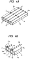
- the aforementioned compression relay terminals 17 are press-fitted in the suitable ones of the press-fitted slits 16e which are required for the circuit construction by the electric wires 15, as shown in Fig. 4.
- the upper and lower electric wires 15 are individually inserted into the paired upper and lower electric wire fitting grooves 16b and 16d having the press-filled compression relay terminals 17 so that they are individually compressed and connected by the upper and lower compression blades 17a and 17b of the compression relay terminals 17.
- the electric wires 15 to be inserted into the individual electric wire fitting grooves 16b and 16d of the aforementioned insulating plate 16 are given different lengths, and a male terminal 18 and a female terminal 19 for external input/output are individually attached to the two ends of each electric wire 15.
- the male terminal 18 and the female terminal 19 can be disposed at arbitrary positions according to the length of the electric wire 15 by raising 18 and 19 individually.
- the paired upper and lower electric wire fitting grooves 16b and 16d are formed straight in the insulating plate 16 at the constant pitch P1 in the transverse direction; the press-fitting slits 16e are formed in the individual electric wire fitting grooves 16b and 16d at the constant pitch P2 in the longitudinal direction; the compression relay terminals 17 are press-fitted in suitable positions of the individual press-fitting slits 16e: and the electric wires 15 are individually fitted in the paired upper and lower electric wire fitting grooves 16b and 16d having the compression relay terminals 17 press-fitted therein.
- the upper and lower electric wires 15 are individually compressed and connected in the upper and lower compression blades 17a and 17b of the compression relay terminals 17 so that the upper and lower electric wires 15 of the insulating plate 16 can be electrically connected.
- the insulating plate 16 can be cut out for use according to the numbers and lengths of the necessary electric wire fitting grooves 16b and 16d in accordance with the different electric connection boxes 9 for different kinds and grades of automobiles so that it can be made common (or standardized) to reduce the fabrication cost of the insulating plate 16.
- the electric wires 15 to be fitted in the electric wire fitting grooves 16b and 16d of the insulating plate 16 are given different lengths so that the external input/output terminals 18 and 19 at the two ends of the electric wires 15 can be disposed at arbitrary positions.
- the upper and lower electric wires 15 are compressed and connected by the upper and lower compression blades 17a and 17b of the compression relay terminals 17 which are press-fitted in suitable positions of the press-fitting slits 16e, so that they can be electrically connected in the insulating plate 16.
- the number of steps of designing the circuit can be drastically reduced, and a slight change in the circuit can be made merely by changing the lengths of the electric wires 15 and the positions of the compression relay terminals 17 thereby to respond the design change promptly.
- the high current region is given a wiring structure similar to that of the bus bars 7(A to C) of the prior art, and the signal portion and the low current region are given the aforementioned wiring structure by the electric wires 15.
- the external input/output terminals 18 and 19 can be disposed at the arbitrary positions to make the arrangement of the insulating plate 16 flexible in the electric connection box 9 and the arranging design feasible.
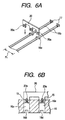
- a jumper terminal 20 having a plurality of compression blades 20a formed in the crosswise direction across the pitch P1 of the electric wire fitting grooves 16b and 16d of the aforementioned insulating plate 16, and the individual compression blades 20a of the jumper terminal 20 are press-fitted in the press-fitting slits 16e of the electric wire fitting grooves 16b and 16d in the individual faces 16a and 16c of the insulating plate 16. Then, the individual compression blades 20a are compressed and connected with the individual electric wires 15.
- the crosswise electric wires 15 in the individual faces 16a and 16c of the insulating plate 16 can be electrically connected so that the compression relay terminals 17 can be made smaller and lighter than those of the case, in which the crosswise electric wires 15 are connected by forming the compression blades on the left and right sides of the compression relay terminals 17, thereby to narrower the electric wire pitch P1.
- short jumper wires (electric wires) 21 are provided and are compressed and connected at their two ends with the compression blades 17a and 17b of the individual compression relay terminals 17 which are press-fitted in the press-fitting slits 16e of the electric wire fitting grooves 16b and 16d in the individual faces 16a and 16c of the insulating plate 16.
- the crosswise electric wires 15 in the individual faces 16a and 16c of the insulating plate 16 can be connected.
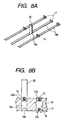
- an input/output male terminal 22 having a compressed blade 22a formed at its lower portion is provided and is press-fitted at its compression blade 22a in the press-fitting slit 16e of the electric wire fitting groove 16b or 16d in each face 16a or 16c of the insulating plate 16. Then, the compression blade 22a is compressed and connected with the electric wire 15.
- the male terminal 22 can be disposed at the position of the press-fitting slit 16e.
- the common insulating plate is prepared such that the paired upper and lower electric wire fitting grooves are formed straight in the plurality in the insulating plate at the constant pitch in the transverse direction, and such that the press-fitting slits are formed in the plurality in the individual electric wire fitting grooves at the constant pitch in the longitudinal direction;
- the compression relay terminals are press-fitted in suitable positions of the individual press-fitting slits: and the electric wires are individually fitted in the paired upper and lower electric wire fitting grooves having the compression relay terminals press-fitted therein.
- the insulating plate can be cut out for use according to the numbers and lengths of the necessary electric wire fitting grooves in accordance with the different electric connection boxes for different kinds and grades of automobiles so that it can be made common (or standardized) to reduce the fabrication cost.
- the electric wires to be fitted in the electric wire fitting grooves of the insulating plate are given different lengths so that the external input/output terminals at the two ends of the electric wires can be disposed at arbitrary positions.
- the upper and lower electric wires are compressed and connected by the upper and lower compression blades of the compression relay terminals which are press-fitted in suitable positions of the press-fitting slits, so that they can be electrically connected in the insulating plate.
- the number of steps of designing the circuit can be drastically reduced, and a slight change in the circuit can be made merely by changing the positions of the compression relay terminals thereby to respond the design change promptly.
- the high current region is given a wiring structure similar to that of the bus bars of the prior art, and the signal portion and the low current region are given the aforementioned wiring structure by the electric wires.
- the external input/output terminals can be disposed at the arbitrary positions to make the arrangement of the insulating plate flexible in the electric connection box and the arranging design feasible.
- the crosswise electric wires can be electrically connected in the individual faces of the insulating plate by the jumper terminal or the jumper wire.
- the compression relay terminals can be made smaller and lighter than those of the case, in which the crosswise electric wires are connected by forming the compression blades on the left and right sides of the compression relay terminals, thereby to narrower the electric wire pitch.
- the input/output terminals are press-fitted in the press-fitting slits and are compressed and connected at their compression blades with the electric wires, as in Aspect 4, the input/output terminals can be disposed at the positions of the press-fitting slits.
Landscapes
- Connections By Means Of Piercing Elements, Nuts, Or Screws (AREA)
- Connection Or Junction Boxes (AREA)
- Multi-Conductor Connections (AREA)
Abstract
Description
Claims (4)
- A connection structure for electric wires to be accomodated in an electric connection box, whereinan insulating plate has a pair of upper and lower electric wire fitting grooves formed straight in upper face and lower face thereof at vertically symmetric positions such that the paired upper and lower electric wire fitting grooves are provided in plurality at a constant pitch in the widthwise direction thereof;press-fitting slits are formed to extend through the paired upper and lower electric wire fitting grooves and are provided in plurality at a constant pitch in the longitudinal direction of the paired upper and lower electric wire fitting grooves;compression relay terminals having compression blades formed at their upper and lower portions are press-fitted into suitable portions of the individual press-fitting slits; andsaid electric wires are individually fitted in the paired upper and lower electric wire fitting grooves, in which said compression relay terminals are press-fitted, so that said upper and lower electric wires are individually compressed and connected by the upper and lower compression blades of said compression relay terminals.
- The electric wire connection structure as set forth in Claim 1, whereina jumper terminal having a plurality of compression blades formed in a crosswise direction across the pitch of wire electric wire fitting grooves is press-fitted in the press-fitting slits of the electric wire fitting grooves in each face of said insulating plate such that individual compression blades thereof are compressed and connected with said individual electric wires.
- The electric wire connection structure as set forth in Claim 1, whereina jumper wire is compressed and connected with the compression blades of the individual relay terminals which are press-fitted in the press-fitting slits of the electric wire fitting grooves in each face of said insulating plate.
- The electric wire connection structure as set forth in Claim 1, whereinan input/output terminal having a compression blade formed is press-fitted in the press-fitting slit of the electric wire fitting groove in each face of said insulating plate so that compression blade thereof is compressed and connected with said electric wire.
Applications Claiming Priority (2)
| Application Number | Priority Date | Filing Date | Title |
|---|---|---|---|
| JP17682499 | 1999-06-23 | ||
| JP11176824A JP2001016744A (en) | 1999-06-23 | 1999-06-23 | Wire connection structure |
Publications (3)
| Publication Number | Publication Date |
|---|---|
| EP1063725A2 true EP1063725A2 (en) | 2000-12-27 |
| EP1063725A3 EP1063725A3 (en) | 2004-09-15 |
| EP1063725B1 EP1063725B1 (en) | 2006-09-27 |
Family
ID=16020492
Family Applications (1)
| Application Number | Title | Priority Date | Filing Date |
|---|---|---|---|
| EP00105089A Expired - Lifetime EP1063725B1 (en) | 1999-06-23 | 2000-03-10 | Connection structure for electric wires |
Country Status (3)
| Country | Link |
|---|---|
| US (1) | US6447325B1 (en) |
| EP (1) | EP1063725B1 (en) |
| JP (1) | JP2001016744A (en) |
Families Citing this family (7)
| Publication number | Priority date | Publication date | Assignee | Title |
|---|---|---|---|---|
| JP2002158047A (en) * | 2000-11-17 | 2002-05-31 | Yazaki Corp | Plate insulator |
| JP2004072934A (en) * | 2002-08-08 | 2004-03-04 | Yazaki Corp | Electrical junction box |
| CN100414195C (en) * | 2003-08-25 | 2008-08-27 | 乐金电子(天津)电器有限公司 | Control box of air conditioner outdoor unit |
| JP4619992B2 (en) * | 2006-05-30 | 2011-01-26 | 矢崎総業株式会社 | Electrical junction box |
| US8212426B2 (en) * | 2008-04-21 | 2012-07-03 | Shimano Inc. | Bicycle electrical wiring unit |
| US20140192457A1 (en) * | 2013-01-10 | 2014-07-10 | Tyco Electronics Corporation | Battery distribution unit |
| DE102013216472A1 (en) * | 2013-08-20 | 2015-02-26 | Brose Fahrzeugteile GmbH & Co. Kommanditgesellschaft, Würzburg | Electrical contact arrangement for an electric motor and method of manufacture |
Family Cites Families (20)
| Publication number | Priority date | Publication date | Assignee | Title |
|---|---|---|---|---|
| FR470887A (en) * | 1914-03-11 | 1914-10-03 | Francisque Nicolas | Mobile saddle support for cycles and other applications |
| JPS6035911A (en) * | 1983-08-05 | 1985-02-23 | 古河電気工業株式会社 | Electric connection box |
| DE3581138D1 (en) * | 1984-08-07 | 1991-02-07 | Sumitomo Wiring Systems | CONNECTOR DEVICE FOR CONNECTING ELECTRICAL CABLES. |
| JPH01173579A (en) * | 1987-12-28 | 1989-07-10 | Yazaki Corp | Multipoint connector |
| JPH02219413A (en) * | 1989-02-16 | 1990-09-03 | Yazaki Corp | electrical junction box |
| FR2650707B1 (en) * | 1989-08-07 | 1991-10-11 | Labinal | SHUNTING DEVICE FOR ELECTRICAL CONDUCTOR BEAMS |
| GB9124180D0 (en) * | 1991-11-14 | 1992-01-08 | Raychem Sa Nv | Electrical connector |
| US5207587A (en) * | 1992-05-27 | 1993-05-04 | General Motors Corporation | Electrical distribution center |
| FR2693318B1 (en) * | 1992-07-03 | 1994-11-18 | Telemecanique | Terminal electrical connection strip. |
| JPH06275346A (en) * | 1993-03-23 | 1994-09-30 | Nippon Burndy Kk | Electric connecting device, electric connecting board used for the same, and electric connector |
| US5501605A (en) * | 1993-06-07 | 1996-03-26 | Yazaki Corporation | Wiring harness assembly for vehicles |
| US5498172A (en) * | 1993-07-30 | 1996-03-12 | Sunx Kabushiki Kaisha | Electrical connector for interconnecting parallel multiconductor cables |
| EP0692850B1 (en) * | 1994-07-15 | 2003-03-12 | Sumitomo Wiring Systems, Ltd. | Electrical connection box |
| US5791933A (en) * | 1994-08-23 | 1998-08-11 | Sumitomo Wiring Systems, Ltd. | Wiring construction of electrical connection box |
| JPH08179885A (en) * | 1994-12-22 | 1996-07-12 | Sharp Corp | Display device |
| JP3075118B2 (en) * | 1994-12-29 | 2000-08-07 | 住友電装株式会社 | Electrical junction box |
| US5888088A (en) * | 1995-02-22 | 1999-03-30 | Sumitomo Wiring Systems, Ltd. | Electrical connection construction of electrical connection box |
| JP3087614B2 (en) * | 1995-06-30 | 2000-09-11 | 住友電装株式会社 | Electrical junction box |
| US5715135A (en) * | 1996-08-12 | 1998-02-03 | General Motors Corporation | Electrical distribution center with two-piece insulation assembly |
| US6220874B1 (en) * | 1998-03-26 | 2001-04-24 | Sumitomo Wiring Systems, Ltd. | Wire harness assembly |
-
1999
- 1999-06-23 JP JP11176824A patent/JP2001016744A/en active Pending
-
2000
- 2000-03-03 US US09/518,271 patent/US6447325B1/en not_active Expired - Fee Related
- 2000-03-10 EP EP00105089A patent/EP1063725B1/en not_active Expired - Lifetime
Also Published As
| Publication number | Publication date |
|---|---|
| EP1063725B1 (en) | 2006-09-27 |
| US6447325B1 (en) | 2002-09-10 |
| EP1063725A3 (en) | 2004-09-15 |
| JP2001016744A (en) | 2001-01-19 |
Similar Documents
| Publication | Publication Date | Title |
|---|---|---|
| US6270361B1 (en) | Connection structure for bus bars | |
| RU2198448C2 (en) | Fusible element of multiple-electrode type and fuse of multiple-electrode type (alternatives) | |
| DE10356754B4 (en) | Fusible link insert and method of making a fuse link insert | |
| EP1017133A2 (en) | Electrical connector housing | |
| EP0700133B1 (en) | Electrical connection box | |
| US5417589A (en) | Linked electrical connectors | |
| EP0694927B1 (en) | Flat cable with conductor ends connectable to connector | |
| US6921301B2 (en) | Blade-contact socket | |
| US6447325B1 (en) | Connection structure for electric wires | |
| EP1289065B1 (en) | Joint connector | |
| US10283308B2 (en) | Busbar | |
| EP0720256B1 (en) | Electrical connection box and contact bonding terminal used therefor | |
| US20010031583A1 (en) | Multipole electrical connector | |
| JP4014881B2 (en) | Electrical connection device | |
| US5893778A (en) | Modular connector | |
| EP1283578A1 (en) | Connector equiped with clamp contacts on a pair of bus bars | |
| JP3562431B2 (en) | Manufacturing method of large busbar | |
| JPH0736430Y2 (en) | Electrical junction box | |
| JPH0583828A (en) | Method for modifying bus bar circuit | |
| JPS5911425Y2 (en) | chained electrical connectors | |
| EP0821439B1 (en) | Modular connector | |
| JP3085208B2 (en) | Electrical junction box | |
| US6141871A (en) | Electrical connection box and a method for forming terminals | |
| JP3364881B2 (en) | Manufacturing method of busbar wiring board | |
| JP3421497B2 (en) | Electrical junction box |
Legal Events
| Date | Code | Title | Description |
|---|---|---|---|
| PUAI | Public reference made under article 153(3) epc to a published international application that has entered the european phase |
Free format text: ORIGINAL CODE: 0009012 |
|
| AK | Designated contracting states |
Kind code of ref document: A2 Designated state(s): AT BE CH CY DE DK ES FI FR GB GR IE IT LI LU MC NL PT SE |
|
| AX | Request for extension of the european patent |
Free format text: AL;LT;LV;MK;RO;SI |
|
| RAP1 | Party data changed (applicant data changed or rights of an application transferred) |
Owner name: SUMITOMO WIRING SYSTEMS, LTD. Owner name: AUTONETWORKS TECHNOLOGIES, LTD. Owner name: SUMITOMO ELECTRIC INDUSTRIES, LTD. |
|
| PUAL | Search report despatched |
Free format text: ORIGINAL CODE: 0009013 |
|
| AK | Designated contracting states |
Kind code of ref document: A3 Designated state(s): AT BE CH CY DE DK ES FI FR GB GR IE IT LI LU MC NL PT SE |
|
| AX | Request for extension of the european patent |
Extension state: AL LT LV MK RO SI |
|
| 17P | Request for examination filed |
Effective date: 20041112 |
|
| 17Q | First examination report despatched |
Effective date: 20050221 |
|
| AKX | Designation fees paid |
Designated state(s): FR |
|
| REG | Reference to a national code |
Ref country code: DE Ref legal event code: 8566 |
|
| GRAP | Despatch of communication of intention to grant a patent |
Free format text: ORIGINAL CODE: EPIDOSNIGR1 |
|
| GRAS | Grant fee paid |
Free format text: ORIGINAL CODE: EPIDOSNIGR3 |
|
| GRAA | (expected) grant |
Free format text: ORIGINAL CODE: 0009210 |
|
| AK | Designated contracting states |
Kind code of ref document: B1 Designated state(s): FR |
|
| ET | Fr: translation filed | ||
| PLBE | No opposition filed within time limit |
Free format text: ORIGINAL CODE: 0009261 |
|
| STAA | Information on the status of an ep patent application or granted ep patent |
Free format text: STATUS: NO OPPOSITION FILED WITHIN TIME LIMIT |
|
| 26N | No opposition filed |
Effective date: 20070628 |
|
| PGFP | Annual fee paid to national office [announced via postgrant information from national office to epo] |
Ref country code: FR Payment date: 20130325 Year of fee payment: 14 |
|
| REG | Reference to a national code |
Ref country code: FR Ref legal event code: ST Effective date: 20141128 |
|
| PG25 | Lapsed in a contracting state [announced via postgrant information from national office to epo] |
Ref country code: FR Free format text: LAPSE BECAUSE OF NON-PAYMENT OF DUE FEES Effective date: 20140331 |