EP1063650A2 - Housing for tape cartridge and mold for forming the same - Google Patents
Housing for tape cartridge and mold for forming the same Download PDFInfo
- Publication number
- EP1063650A2 EP1063650A2 EP00111892A EP00111892A EP1063650A2 EP 1063650 A2 EP1063650 A2 EP 1063650A2 EP 00111892 A EP00111892 A EP 00111892A EP 00111892 A EP00111892 A EP 00111892A EP 1063650 A2 EP1063650 A2 EP 1063650A2
- Authority
- EP
- European Patent Office
- Prior art keywords
- cartridge
- mold
- housing
- tape
- recorder
- Prior art date
- Legal status (The legal status is an assumption and is not a legal conclusion. Google has not performed a legal analysis and makes no representation as to the accuracy of the status listed.)
- Granted
Links
- 230000037431 insertion Effects 0.000 claims abstract description 19
- 238000003780 insertion Methods 0.000 claims abstract description 19
- 238000000465 moulding Methods 0.000 description 12
- 239000002184 metal Substances 0.000 description 4
- 239000011347 resin Substances 0.000 description 3
- 229920005989 resin Polymers 0.000 description 3
- 230000001174 ascending effect Effects 0.000 description 1
- 238000010276 construction Methods 0.000 description 1
- 230000000694 effects Effects 0.000 description 1
Images



Classifications
-
- G—PHYSICS
- G11—INFORMATION STORAGE
- G11B—INFORMATION STORAGE BASED ON RELATIVE MOVEMENT BETWEEN RECORD CARRIER AND TRANSDUCER
- G11B23/00—Record carriers not specific to the method of recording or reproducing; Accessories, e.g. containers, specially adapted for co-operation with the recording or reproducing apparatus ; Intermediate mediums; Apparatus or processes specially adapted for their manufacture
- G11B23/02—Containers; Storing means both adapted to cooperate with the recording or reproducing means
- G11B23/04—Magazines; Cassettes for webs or filaments
- G11B23/08—Magazines; Cassettes for webs or filaments for housing webs or filaments having two distinct ends
- G11B23/087—Magazines; Cassettes for webs or filaments for housing webs or filaments having two distinct ends using two different reels or cores
- G11B23/08707—Details
- G11B23/08785—Envelopes
-
- B—PERFORMING OPERATIONS; TRANSPORTING
- B29—WORKING OF PLASTICS; WORKING OF SUBSTANCES IN A PLASTIC STATE IN GENERAL
- B29C—SHAPING OR JOINING OF PLASTICS; SHAPING OF MATERIAL IN A PLASTIC STATE, NOT OTHERWISE PROVIDED FOR; AFTER-TREATMENT OF THE SHAPED PRODUCTS, e.g. REPAIRING
- B29C45/00—Injection moulding, i.e. forcing the required volume of moulding material through a nozzle into a closed mould; Apparatus therefor
- B29C45/17—Component parts, details or accessories; Auxiliary operations
- B29C45/26—Moulds
- B29C45/33—Moulds having transversely, e.g. radially, movable mould parts
-
- G—PHYSICS
- G11—INFORMATION STORAGE
- G11B—INFORMATION STORAGE BASED ON RELATIVE MOVEMENT BETWEEN RECORD CARRIER AND TRANSDUCER
- G11B23/00—Record carriers not specific to the method of recording or reproducing; Accessories, e.g. containers, specially adapted for co-operation with the recording or reproducing apparatus ; Intermediate mediums; Apparatus or processes specially adapted for their manufacture
- G11B23/02—Containers; Storing means both adapted to cooperate with the recording or reproducing means
- G11B23/04—Magazines; Cassettes for webs or filaments
- G11B23/08—Magazines; Cassettes for webs or filaments for housing webs or filaments having two distinct ends
- G11B23/107—Magazines; Cassettes for webs or filaments for housing webs or filaments having two distinct ends using one reel or core, one end of the record carrier coming out of the magazine or cassette
Definitions
- This invention relates to a housing for tape cartridge to be used with a recording-reproducing apparatus (hereinafter called a "recorder”), more particularly to a housing for tape cartridge of the type having positioning walls for insertion into a recorder, and also relates to a mold for forming the housing.
- a recording-reproducing apparatus hereinafter called a "recorder”
- recorders For cartridges holding a reel or reels around which a length of magnetic tape is wound, recorders have positioning means to control the position of each such cartridge inserted into the machine, whereas the cartridge is formed with positioning ribs for engagement with the positioning means.
- Japanese Patent Application Kokoku No. 63-16834 discloses a cartridge formed with low positioning ribs formed on both left and right of a tape draw-out portion at the front of the cartridge. After position control with such means, reference pins from a recorder gain entrance into reference holes formed in the underside of the cartridge to effect more precise positioning.
- the prior art teaches forming positioning ribs in the tape draw-out region at the front of a cartridge, keeping them low compared with the height of side walls of the housing. Structural limitation, however, does not favor providing ribs in that location and it is preferable to form them instead on the outer surface of side wall of the housing in the direction of cartridge insertion into a recorder.
- FIGS. 6 and 7 illustrate the exterior side wall of an upper or lower casing of a conventional cartridge housing and a mold of the prior art for forming the casing.
- FIG. 6(a) shows a mold 6 closed for resin molding and FIG. 6(b), the mold opened after molding.
- Mold 6 is composed of a fixed mold part 61 and a movable mold part 62. It performs molding as molten resin 67 is poured into a mold cavity defined between the two mold parts 61, 62 via a gate 66 (FIG. 6(a)). After molding, the molded article is released from the mold by ascending ejector pins 64 (FIG. 6(b)).
- the surface of fixed mold part 61 that makes the outer surface of side wall 26 of a casing has a draft or inclination of ⁇ (usually from 0.5 to several degrees) to the perpendicular.
- ⁇ usually from 0.5 to several degrees
- side wall 26 of a casing molded as in FIG. 7 (an enlarged view of the circled portion C in FIG. 6(b)) has an inclination ⁇ corresponding to the draft, and when it is partly utilized in positioning, the afore-described problem arises.
- the present invention has for its object to achieve positioning of a cartridge housing with good precision by utilizing its side wall as a positioning plane.
- the invention realizes the above object by a housing for tape cartridge which holds therein a tape reel on which a medium in the form of a tape is wound, characterized in that an outer surface portion of a side wall, out of surrounding walls, of the housing facing the direction of cartridge insertion into a recorder has a draft of zero degree (perpendicular to the direction of insertion) where it comes in contact with positioning means of the recorder.
- the invention also achieves the object by a mold for forming such a housing, characterized in that the mold portion that forms an outer surface portion of a side wall, out of surrounding walls, of the housing facing the direction of cartridge insertion into a recorder is constituted by a slide having a plane perpendicular to the direction of insertion.
- the cartridge can be accurately positioned within a recorder since a perpendicular positioning plane formed on the wall of the cartridge housing in the direction of insertion into the recorder comes in contact with positioning means of the recorder having perpendicular contacting surface.
- the amount of insertion is made stable, allowing precise fitting of reference pins of the recorder into reference holes formed in the underside of the cartridge housing.
- FIG. 1 is an exploded view of a tape cartridge embodying the present invention.
- the cartridge holds a single tape reel 3 on which a length of tape is wound turnably within a housing composed of an upper casing 1 and a lower casing 2.
- Lower casing 2 has a hole through which a drive shaft of a recorder is to be inserted.
- Upper and lower casings 1, 2 have openings 12, 22, respectively, through which the tape is drawn out.
- Tape reel 3 is an integral assembly of an upper flange 31, a hub 32 formed in one piece with a lower flange 33, and a metal disk 7 fitted to the underside of hub 32.
- teeth 36 (FIG. 2) are formed in one piece with hub 32 to mesh with a drive shaft of a recorder.
- Metal disk 7 is magnetically attracted by the drive shaft to turn tape reel 3.
- Hub 32 has a tooth-like part 35 formed on its inner surface to be in mesh with a brake lock 5 so as to prevent unwanted turning of tape reel 3 when the latter is not in use.
- Brake lock 5 has a tooth-like part 51 formed on its underside in mesh with the corresponding part 35 of hub 32. Brake lock 5 is normally urged in the braking position by a brake spring 4.
- a follower projection 52 of brake lock 5 has a cruciform recess which slidably engages with a guide member (not shown), allowing brake lock 5 to move up and down positively between a lower braking position and an upper brake release position.
- a release pin (not shown) that comes out of the recorder into the cartridge lifts brake lock 5 upwardly while metal disk 7 secured to tape reel 3 is being sucked up by magnetic means of the recorder, whereby teeth 51 and corresponding teeth 35 of tape reel 3 are disengaged, setting the reel free to turn.
- leader end of tape is partly wound round a pin member 81, which in turn is fixedly fitted in a pin-receiving groove 83 of a leader block 82.
- Leader block 82 in this state is located in openings 12, 13.
- leader block 82 is gripped by a draw member that comes in from the recorder, and tape is threaded along a tape path to a take up reel of the recorder and is finally held in a recess formed in the outer periphery of the take up reel.
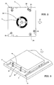
- FIG. 2 is a plan view of the cartridge as viewed from below its underside.
- FIG. 3 is a perspective view of the cartridge as set on a holder of a recorder.
- the insertion point of the cartridge is defined by two positioning posts 92 provided on holder 9.
- Designated 91 are guides along which the cartridge is inserted in place.
- the height of positioning posts 92 reaches the side wall of upper casing 1, and both upper and lower casings 1, 2 must be perpendicular on this side.
- both upper and lower casings 1, 2 must be perpendicular on this side.
- a mold including a slide as illustrated in FIG. 4 is used to form an outer surface of side wall 26 having a perpendicular plane (with a draft of zero degree).
- FIG. 4(a) shows a mold 6 closed for resin molding and FIG. 4(b) shows the mold opened after molding.
- Mold 6 comprises a fixed mold part 61 and a movable mold part 62.
- a slide 63 having a perpendicular molding face and capable of sliding in the direction normal to the mold opening direction is used as a perpendicular face molding unit of movable mold part 62.
- the upper portion on the side of slide 63 opposite to the perpendicular molding face is sloped 68, and the sloped portion 68 is adapted to engage with a sloped portion 69 of fixed mold part 61.
- the molding face of slide 63 is made perpendicular and, as illustrated in FIG. 5 that is an enlarged view of the encircled portion B in FIG. 4(b), the positioning plane for the side wall 26 of lower casing (and side wall 16 of upper casing too) is perpendicular, making accurate positioning of the cartridge possible.
- positioning for the direction of cartridge insertion into a recorder is made precise and dependable, and cartridge loading in reference position is stabilized with added reliability.
Landscapes
- Engineering & Computer Science (AREA)
- Manufacturing & Machinery (AREA)
- Mechanical Engineering (AREA)
- Moulds For Moulding Plastics Or The Like (AREA)
- Packaging Of Annular Or Rod-Shaped Articles, Wearing Apparel, Cassettes, Or The Like (AREA)
Abstract
Description
Claims (2)
- A housing for tape cartridge which holds therein a tape reel on which a medium in the form of a tape is wound, characterized in thatan outer surface portion of a side wall, out of surrounding walls, of the housing facing the direction of cartridge insertion into a recording-reproducing apparatus has a draft of zero degree where it comes in contact with positioning means of the apparatus.
- A mold for forming a housing for tape cartridge which holds therein a tape reel on which a medium in the form of a tape is wound, characterized in thatthe mold portion that forms an outer surface portion of a side wall, out of surrounding walls, of the housing facing the direction of cartridge insertion into a recording-reproducing apparatus is constituted by a slide having a plane perpendicular to the direction of insertion.
Applications Claiming Priority (2)
| Application Number | Priority Date | Filing Date | Title |
|---|---|---|---|
| JP17516499 | 1999-06-22 | ||
| JP11175164A JP2001006321A (en) | 1999-06-22 | 1999-06-22 | Case for tape cartridge and its molding die |
Publications (3)
| Publication Number | Publication Date |
|---|---|
| EP1063650A2 true EP1063650A2 (en) | 2000-12-27 |
| EP1063650A3 EP1063650A3 (en) | 2001-09-19 |
| EP1063650B1 EP1063650B1 (en) | 2006-03-29 |
Family
ID=15991394
Family Applications (1)
| Application Number | Title | Priority Date | Filing Date |
|---|---|---|---|
| EP00111892A Expired - Lifetime EP1063650B1 (en) | 1999-06-22 | 2000-06-13 | Housing for tape cartridge and mold for forming the same |
Country Status (4)
| Country | Link |
|---|---|
| US (1) | US6547174B1 (en) |
| EP (1) | EP1063650B1 (en) |
| JP (1) | JP2001006321A (en) |
| DE (1) | DE60026900T2 (en) |
Families Citing this family (4)
| Publication number | Priority date | Publication date | Assignee | Title |
|---|---|---|---|---|
| US6764038B2 (en) * | 2001-01-19 | 2004-07-20 | Fuji Photo Film Co., Ltd. | Magnetic tape cartridge |
| JP2003036627A (en) * | 2001-07-23 | 2003-02-07 | Fuji Photo Film Co Ltd | Recording tape cartridge |
| JP2005085380A (en) * | 2003-09-09 | 2005-03-31 | Fuji Photo Film Co Ltd | Recording tape cartridge |
| CN111055407B (en) * | 2019-12-31 | 2024-12-20 | 宁波爱如斯智能科技有限公司 | Tape shell holder molding die |
Family Cites Families (28)
| Publication number | Priority date | Publication date | Assignee | Title |
|---|---|---|---|---|
| JPS5124689A (en) | 1974-08-23 | 1976-02-28 | Kanegafuchi Chemical Ind | FUIRUMUYOAKURIRUKEIJUSHINO SEIZOHOHO |
| JPS605040A (en) | 1983-06-21 | 1985-01-11 | Hitachi Cable Ltd | Polarization keeping optical fiber |
| US4668062A (en) | 1985-03-04 | 1987-05-26 | Polaroid Corporation | Apparatus for precluding rotational movement of an advancing film unit |
| JPS60258783A (en) | 1985-04-11 | 1985-12-20 | Hitachi Maxell Ltd | Tape cartridge |
| US4828201A (en) * | 1986-03-21 | 1989-05-09 | Laser Magnetic Storage International Company | Apparatus for coupling a drive motor to a leader block loading/unloading mechanism |
| JPS6316834A (en) | 1986-07-10 | 1988-01-23 | Ishikawajima Harima Heavy Ind Co Ltd | Continuous pipe manufacturing method and device |
| US4735377A (en) * | 1986-11-24 | 1988-04-05 | Zuehsow Richard A | Remote control holder |
| JP2513201B2 (en) | 1987-01-09 | 1996-07-03 | ソニー株式会社 | Molding method for cassette casing |
| US4775115A (en) * | 1987-04-13 | 1988-10-04 | Shape Inc. | Single reel tape cartridge used with a leader block |
| US4977474A (en) * | 1988-02-01 | 1990-12-11 | Fuji Photo Film Co., Ltd. | Magnetic tape cartridge requiring uniform force during leader block attachment and detachment |
| DE8806117U1 (en) | 1988-05-09 | 1988-06-23 | Koose, Rudolf, 4600 Dortmund | Split injection mould, particularly for the production of bottle crates or the like. |
| US5472655A (en) | 1988-11-16 | 1995-12-05 | Fuji Photo Film Co., Ltd. | Method and apparatus for molding magnetic tape cassette |
| US5128815A (en) * | 1990-12-06 | 1992-07-07 | Storage Technology Corporation | Apparatus for interfacing a cartridge tape with a helical scan transport |
| US5209425A (en) * | 1991-09-06 | 1993-05-11 | Minnesota Mining And Manufacturing Company | Single reel cartridge with thinner cover and leader block area dimensional stability |
| JP2939951B2 (en) * | 1991-10-28 | 1999-08-25 | 三菱マテリアル株式会社 | Mold device for molding cassette tape storage case and its base |
| US5261626A (en) * | 1992-02-10 | 1993-11-16 | Minnesota Mining And Manufacturing Company | Magnetic tape cartridge having self docking leader block |
| JP3239420B2 (en) * | 1992-02-24 | 2001-12-17 | ソニー株式会社 | Tape cassette |
| US5333806A (en) | 1992-06-03 | 1994-08-02 | Verbatim Corporation | Magnetic tape cartridge |
| JPH065040A (en) * | 1992-06-18 | 1994-01-14 | Mitsubishi Materials Corp | Resin container |
| JPH0737357A (en) | 1993-07-20 | 1995-02-07 | Sony Corp | Cassette half |
| JP3466283B2 (en) * | 1993-09-13 | 2003-11-10 | 東北リコー株式会社 | Stencil making machine and master storage unit |
| US5868333A (en) * | 1997-07-25 | 1999-02-09 | Seagate Technology, Inc. | Tape media cartridge system and components thereof and methods of making and using the same |
| JPH1148295A (en) | 1997-07-31 | 1999-02-23 | Fuji Photo Film Co Ltd | Housing case for magnetic tape cassette and mold for molding the case |
| US5883771A (en) * | 1997-09-25 | 1999-03-16 | Hewlett-Packard Company | Single reel tape cartridge with locking leader block |
| US6332997B1 (en) * | 1998-05-26 | 2001-12-25 | Hardigg Industries Inc. | Method and apparatus for making a one piece battery jar |
| US5969913A (en) * | 1998-06-11 | 1999-10-19 | Dimation Corp | Data storage tape cartridge with misinsertion notch |
| US5927633A (en) * | 1998-07-22 | 1999-07-27 | Hewlett-Packard Company | Resiliently biased parking seat for receiving the leader pin of a single reel tape cartridge |
| ES2183624T3 (en) * | 1998-11-12 | 2003-03-16 | Masonite Corp | PROCEDURE OF PRODUCTION OF A BOXED BOARD AND RESULTING PRODUCT. |
-
1999
- 1999-06-22 JP JP11175164A patent/JP2001006321A/en active Pending
-
2000
- 2000-06-09 US US09/591,247 patent/US6547174B1/en not_active Expired - Lifetime
- 2000-06-13 EP EP00111892A patent/EP1063650B1/en not_active Expired - Lifetime
- 2000-06-13 DE DE60026900T patent/DE60026900T2/en not_active Expired - Fee Related
Also Published As
| Publication number | Publication date |
|---|---|
| JP2001006321A (en) | 2001-01-12 |
| EP1063650B1 (en) | 2006-03-29 |
| DE60026900D1 (en) | 2006-05-18 |
| US6547174B1 (en) | 2003-04-15 |
| EP1063650A3 (en) | 2001-09-19 |
| DE60026900T2 (en) | 2006-10-05 |
Similar Documents
| Publication | Publication Date | Title |
|---|---|---|
| US4799123A (en) | Disc cartridge | |
| US6264126B1 (en) | Tape cartridge | |
| US4702506A (en) | Magnet catcher for doors | |
| US4672498A (en) | Tape cassette having reels with limited axial travel | |
| EP0111876A2 (en) | Recording tape cartridge | |
| EP0175347A2 (en) | A tape cassette | |
| EP1058259B1 (en) | Tape cartridge | |
| US6547174B1 (en) | Housing for tape cartridge and hold for mold for forming the same | |
| EP0323199B1 (en) | Magnetic tape cassette | |
| US6474978B2 (en) | Magnetic tape cassette molding apparatus | |
| EP0324458B1 (en) | Magnetic tape cassette having improved erasure preventing device | |
| EP0501050B1 (en) | Unit type mold for injection molding | |
| EP0568060A2 (en) | Cassette screw bosses having ribbed surfaces | |
| JPS60231985A (en) | Magnetic disk cassette | |
| US4635879A (en) | Tape cassette | |
| US7270780B2 (en) | Molding mold, molding method and tape cartridge | |
| EP0448320A2 (en) | Shutter for cartridge and apparatus for molding same | |
| US4786012A (en) | Miniature type tape cassette | |
| EP0142807A2 (en) | Tape Cartridge | |
| EP0450976A2 (en) | Tape cassette | |
| US6056224A (en) | Magnetic tape cassette | |
| US7048221B2 (en) | Door member for tape cartridge, and tape cartridge | |
| KR100375253B1 (en) | Record and playback device | |
| JPH0521756Y2 (en) | ||
| EP1327987A1 (en) | Magnetic tape cartridge |
Legal Events
| Date | Code | Title | Description |
|---|---|---|---|
| PUAI | Public reference made under article 153(3) epc to a published international application that has entered the european phase |
Free format text: ORIGINAL CODE: 0009012 |
|
| AK | Designated contracting states |
Kind code of ref document: A2 Designated state(s): DE GB Kind code of ref document: A2 Designated state(s): AT BE CH CY DE DK ES FI FR GB GR IE IT LI LU MC NL PT SE |
|
| AX | Request for extension of the european patent |
Free format text: AL;LT;LV;MK;RO;SI |
|
| PUAL | Search report despatched |
Free format text: ORIGINAL CODE: 0009013 |
|
| AK | Designated contracting states |
Kind code of ref document: A3 Designated state(s): AT BE CH CY DE DK ES FI FR GB GR IE IT LI LU MC NL PT SE |
|
| AX | Request for extension of the european patent |
Free format text: AL;LT;LV;MK;RO;SI |
|
| RIC1 | Information provided on ipc code assigned before grant |
Free format text: 7G 11B 23/107 A, 7G 11B 23/087 B, 7B 29C 45/33 B |
|
| 17P | Request for examination filed |
Effective date: 20020314 |
|
| AKX | Designation fees paid |
Free format text: DE GB |
|
| 17Q | First examination report despatched |
Effective date: 20040331 |
|
| GRAP | Despatch of communication of intention to grant a patent |
Free format text: ORIGINAL CODE: EPIDOSNIGR1 |
|
| GRAS | Grant fee paid |
Free format text: ORIGINAL CODE: EPIDOSNIGR3 |
|
| GRAA | (expected) grant |
Free format text: ORIGINAL CODE: 0009210 |
|
| AK | Designated contracting states |
Kind code of ref document: B1 Designated state(s): DE GB |
|
| REG | Reference to a national code |
Ref country code: GB Ref legal event code: FG4D |
|
| REF | Corresponds to: |
Ref document number: 60026900 Country of ref document: DE Date of ref document: 20060518 Kind code of ref document: P |
|
| PLBE | No opposition filed within time limit |
Free format text: ORIGINAL CODE: 0009261 |
|
| STAA | Information on the status of an ep patent application or granted ep patent |
Free format text: STATUS: NO OPPOSITION FILED WITHIN TIME LIMIT |
|
| 26N | No opposition filed |
Effective date: 20070102 |
|
| PGFP | Annual fee paid to national office [announced via postgrant information from national office to epo] |
Ref country code: DE Payment date: 20070607 Year of fee payment: 8 |
|
| PGFP | Annual fee paid to national office [announced via postgrant information from national office to epo] |
Ref country code: GB Payment date: 20070613 Year of fee payment: 8 |
|
| GBPC | Gb: european patent ceased through non-payment of renewal fee |
Effective date: 20080613 |
|
| PG25 | Lapsed in a contracting state [announced via postgrant information from national office to epo] |
Ref country code: DE Free format text: LAPSE BECAUSE OF NON-PAYMENT OF DUE FEES Effective date: 20090101 |
|
| PG25 | Lapsed in a contracting state [announced via postgrant information from national office to epo] |
Ref country code: GB Free format text: LAPSE BECAUSE OF NON-PAYMENT OF DUE FEES Effective date: 20080613 |