EP1063644A2 - Method of compensating for tilt and/or defocus and apparatus therefor - Google Patents
Method of compensating for tilt and/or defocus and apparatus therefor Download PDFInfo
- Publication number
- EP1063644A2 EP1063644A2 EP00305348A EP00305348A EP1063644A2 EP 1063644 A2 EP1063644 A2 EP 1063644A2 EP 00305348 A EP00305348 A EP 00305348A EP 00305348 A EP00305348 A EP 00305348A EP 1063644 A2 EP1063644 A2 EP 1063644A2
- Authority
- EP
- European Patent Office
- Prior art keywords
- tilt
- recording
- defocus
- mark
- compensating
- Prior art date
- Legal status (The legal status is an assumption and is not a legal conclusion. Google has not performed a legal analysis and makes no representation as to the accuracy of the status listed.)
- Granted
Links
Images















Classifications
-
- G—PHYSICS
- G11—INFORMATION STORAGE
- G11B—INFORMATION STORAGE BASED ON RELATIVE MOVEMENT BETWEEN RECORD CARRIER AND TRANSDUCER
- G11B7/00—Recording or reproducing by optical means, e.g. recording using a thermal beam of optical radiation by modifying optical properties or the physical structure, reproducing using an optical beam at lower power by sensing optical properties; Record carriers therefor
- G11B7/12—Heads, e.g. forming of the optical beam spot or modulation of the optical beam
- G11B7/125—Optical beam sources therefor, e.g. laser control circuitry specially adapted for optical storage devices; Modulators, e.g. means for controlling the size or intensity of optical spots or optical traces
- G11B7/126—Circuits, methods or arrangements for laser control or stabilisation
-
- G—PHYSICS
- G11—INFORMATION STORAGE
- G11B—INFORMATION STORAGE BASED ON RELATIVE MOVEMENT BETWEEN RECORD CARRIER AND TRANSDUCER
- G11B7/00—Recording or reproducing by optical means, e.g. recording using a thermal beam of optical radiation by modifying optical properties or the physical structure, reproducing using an optical beam at lower power by sensing optical properties; Record carriers therefor
- G11B7/004—Recording, reproducing or erasing methods; Read, write or erase circuits therefor
- G11B7/0045—Recording
-
- G—PHYSICS
- G11—INFORMATION STORAGE
- G11B—INFORMATION STORAGE BASED ON RELATIVE MOVEMENT BETWEEN RECORD CARRIER AND TRANSDUCER
- G11B7/00—Recording or reproducing by optical means, e.g. recording using a thermal beam of optical radiation by modifying optical properties or the physical structure, reproducing using an optical beam at lower power by sensing optical properties; Record carriers therefor
- G11B7/12—Heads, e.g. forming of the optical beam spot or modulation of the optical beam
- G11B7/135—Means for guiding the beam from the source to the record carrier or from the record carrier to the detector
- G11B7/1372—Lenses
-
- G—PHYSICS
- G11—INFORMATION STORAGE
- G11B—INFORMATION STORAGE BASED ON RELATIVE MOVEMENT BETWEEN RECORD CARRIER AND TRANSDUCER
- G11B7/00—Recording or reproducing by optical means, e.g. recording using a thermal beam of optical radiation by modifying optical properties or the physical structure, reproducing using an optical beam at lower power by sensing optical properties; Record carriers therefor
- G11B7/08—Disposition or mounting of heads or light sources relatively to record carriers
- G11B7/09—Disposition or mounting of heads or light sources relatively to record carriers with provision for moving the light beam or focus plane for the purpose of maintaining alignment of the light beam relative to the record carrier during transducing operation, e.g. to compensate for surface irregularities of the latter or for track following
- G11B7/0908—Disposition or mounting of heads or light sources relatively to record carriers with provision for moving the light beam or focus plane for the purpose of maintaining alignment of the light beam relative to the record carrier during transducing operation, e.g. to compensate for surface irregularities of the latter or for track following for focusing only
-
- G—PHYSICS
- G11—INFORMATION STORAGE
- G11B—INFORMATION STORAGE BASED ON RELATIVE MOVEMENT BETWEEN RECORD CARRIER AND TRANSDUCER
- G11B7/00—Recording or reproducing by optical means, e.g. recording using a thermal beam of optical radiation by modifying optical properties or the physical structure, reproducing using an optical beam at lower power by sensing optical properties; Record carriers therefor
- G11B7/08—Disposition or mounting of heads or light sources relatively to record carriers
- G11B7/09—Disposition or mounting of heads or light sources relatively to record carriers with provision for moving the light beam or focus plane for the purpose of maintaining alignment of the light beam relative to the record carrier during transducing operation, e.g. to compensate for surface irregularities of the latter or for track following
- G11B7/095—Disposition or mounting of heads or light sources relatively to record carriers with provision for moving the light beam or focus plane for the purpose of maintaining alignment of the light beam relative to the record carrier during transducing operation, e.g. to compensate for surface irregularities of the latter or for track following specially adapted for discs, e.g. for compensation of eccentricity or wobble
- G11B7/0956—Disposition or mounting of heads or light sources relatively to record carriers with provision for moving the light beam or focus plane for the purpose of maintaining alignment of the light beam relative to the record carrier during transducing operation, e.g. to compensate for surface irregularities of the latter or for track following specially adapted for discs, e.g. for compensation of eccentricity or wobble to compensate for tilt, skew, warp or inclination of the disc, i.e. maintain the optical axis at right angles to the disc
-
- G—PHYSICS
- G11—INFORMATION STORAGE
- G11B—INFORMATION STORAGE BASED ON RELATIVE MOVEMENT BETWEEN RECORD CARRIER AND TRANSDUCER
- G11B7/00—Recording or reproducing by optical means, e.g. recording using a thermal beam of optical radiation by modifying optical properties or the physical structure, reproducing using an optical beam at lower power by sensing optical properties; Record carriers therefor
- G11B7/24—Record carriers characterised by shape, structure or physical properties, or by the selection of the material
Definitions
- the present invention relates to a method of compensating for tilt and/or defocus and an apparatus therefor, and more particularly, to a method of compensating for tilt/defocus by controlling the power and/or time required for recording according to the amount of tilt/defocus of an optical recording medium, and an apparatus therefor.
- tolerances for radial tilt and tangential tilt in a current digital versatile disc-random access memory are 0.7°and 0.3°, respectively.
- the basic characteristics of a disc must be met, while remaining within these tolerances. For example, power, such as write power and erase power, must be maintained at level which is sufficient to obtain the write characteristics defined in a disc specification.
- Equation 1 expresses coma aberration.
- Comma Aberration ( n 2-1 2 n 3 * d * NA 3 wavelength ) * ( tilt * ⁇ 180 )
- n is the refractivity of a substrate
- d is the thickness of the substrate
- NA is the numerical aperture of an object lens
- Figure 1 illustrates coma aberration in 3 dimensions according to wavelength and NA, when the thickness of a substrate is 0.6mm, the refractivity of a substrate is 1.5, and tilt is 0.5°, using the equation 1.
- the figure shows that coma aberration increases as wavelength becomes shorter and numerical aperture becomes greater.
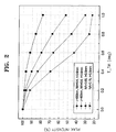
- Figure 2 illustrates changes in beam intensity with respect to tilt, and the abscissa represents tilt while the ordinate represents beam peak intensity.
- recording beam intensity decreases at a wavelength of 400 nm more rapidly at a wavelength of 650 nm. If recording is performed under this condition, the desired length and width of a mark cannot be recorded.
- NA As the NA increases, beam intensity decreases even at the same wavelength of 400 nm and 0.6 mm substrate thickness (t).
- the figure shows that as tilt increases, spot size increases more at a wavelength of 400 nm than at a wavelength of 650 nm, and, as NA increases, spot size increases even at the same wavelength of 400 nm.
- the figure shows that as tilt increases, the maximum temperature (Tmax) decreases more rapidly at a wavelength of 400 nm than at a wavelength of 650 nm, and, as write power (P w ) increases, the maximum temperature (Tmax) decreases even at the same wavelength of 400 nm. However, at a wavelength of 650 nm, the maximum temperature is insensitive to changes in write power (P w ).
- the laser diode As the luminance effect of a short wavelength laser diode, which is used as a light source, lowers when the power emitted therefrom changes according to temperature change, the laser diode must emit luminance stably in order to read information recorded on a disc without erros and to raise the reliability of an optical disc system.
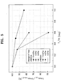
- Figure 5 shows that as tilt increases, the maximum temperature (Tmax) decreases more rapidly at a wavelength of 400 nm than at a wavelength of 650 nm, and, as write time (T w ) increases, the maximum temperature (Tmax) decreases even at the same wavelength of 400 nm. However, at a wavelength of 650 nm, the maximum temperature is insensitive to changes in write time (T w ).
- tilt margin can be extended by making the substrate thickness of a disc, which is currently 0.6mm, thinner using the equation 1 shown in the table.
- a substrate thickness of a disc thinner than 0.6 mm causes problems in manufacturing aspect or in characteristic aspect, tilt compensation cannot be performed simply by manufacturing a substrate thinner than 0.6 mm.
- defocus margin becomes smaller, and therefore, a problem may occur in recording due to even a small degree of defocus. This will now be explained referring to Figures 6 and 7, showing beam intensity and spot size, respectively, with respect to defocus in red wavelength and blue wavelength.
- Figure 6 illustrates changes in beam peak intensity with respect to defocus, and the abscissa represents defocus, while the ordinate shows normalized values of beam peak intensity.
- incidence beam intensity decreases more rapidly at a wavelength of 400 nm and 0.65 NA than at a wavelength of 650 nm and 0.6 NA.
- NA increases, beam intensity decreases even in the same wavelength.
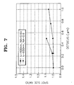
- Figure 7 illustrates changes in beam spot size with respect to defocus, and the abscissa represents defocus, while the ordinate shows spot size ratio.
- spot size increases more at a wavelength of 400 nm than at a wavelength of 650 nm.
- NA increases, spot size increases even for the same wavelength.
- Figure 8 illustrates changes in beam profile when defocus and tilt occur at the same time.
- Curve 1 shows a normal-state beam shape
- curve 2 shows the beam shape when defocus is 0.25 ⁇ m
- curve 3 shows the beam shape when defocus is 0.5 ⁇ m
- curve 4 shows the beam shape when tilt is 0.5°
- curve 5 shows the beam shape when tilt is 0.5° and defocus is 0.25 ⁇ m
- curve 6 shows the beam shape when tilt is 0.5° and defocus is 0.5 ⁇ m.
- Figure 9 illustrates changes in beam spot size and peak power intensity when defocus and tilt occur at the same time, and the abscissa shows a normal case 1, a case 2 where defocus is 0.25 ⁇ m, a case 3 where defocus is 0.5 ⁇ , a case 4 where tilt is 0.5°, a case 5 where tilt is 0.5° and defocus is 0.25 ⁇ m, and a case 6 where tilt is 0.5° and defocus is 0.5 ⁇ m.
- the ordinate shows the normalized value of peak intensity when tilt and defocus occur for peak intensity in a normal state and the normalized value of spot size when tilt and defocus occur for spot size in a normal state.
- peak power intensity decreases and spot size increases. Peak power intensity decreases more and spot size increases more in a case where tilt and defocus occur at the same time, than in a case where any one of defocus and tilt occurs.
- a method of compensating for tilt of an optical recording medium comprising the steps of: (a) detecting the tilt of the optical recording medium; and (b) compensating a recording signal having a predetermined recording pattern using a predetermined scheme with respect to the detected tilt.
- the predetermined scheme adjusts an optical power level required for recording the recording signal.
- the predetermined scheme adjusts time required for recording the recording signal.
- the step (b) further comprises the sub-steps of: (bl) shifting recording pattern with respect to detected tilt; and (b2) adjusting power and/or time required for recording with respect to the detected tilt in order to compensate the size of a recording mark corresponding to the recording signal.
- the length of the mark is compensated for by adjusting the write power
- the width of the mark is compensated for by adjusting the write time
- the length of the mark is compensated by adjusting the write power
- the width of the mark is compensated for by adjusting the ending time of the first pulse and/or the starting time of the last pulse of the recording pattern.
- the length of the mark is compensated for by adjusting write power
- the width of the mark is compensated for by adjusting write power of a multi-pulse chain of recording pattern.
- a method for compensating input data for tilt of an optical recording medium which records marks and spaces by write pulses having a predetermined recording pattern
- the method comprising the steps of: (a) detecting the tilt of the optical recording medium; and (b) adaptively compensating the recording pattern with respect to the tilt detected in the step (a), using a memory storing power and/or time, etc., required for recording in order to compensate for the amount of shift of the recording pattern, and the length and the width of a mark with respect to tilt and/or the length of a mark.
- a method for compensating for defocus of an optical recording medium which can record and rewrite data, the method comprising the steps of: (a) detecting the defocus of the optical recording medium; and (b) performing compensating recording by a predetermined scheme with respect to the detected defocus.
- the predetermined scheme adjust the level of optical power with respect to the detected defocus.
- a method of compensating for tilt and defocus of an optical recording medium comprising the steps of: (a) detecting defocus of the optical recording medium; (b) compensating for write pulse having a predetermined recording pattern by a predetermined scheme with respect to detected defocus; (c) detecting the tilt of the optical recording medium; and (d) compensating write pulse having a predetermined recording pattern with respect to the detected tilt.
- the predetermined scheme adjusts the level of optical power with respect to the detected defocus.
- the step (d) further comprising the sub-steps of: (d1) shifting the recording pattern by an amount equal to the amount by which the recording pattern was shifted due to tilt in a direction which is opposite to the direction in which the recording pattern was shifted due to tilt, with respect to detected tilt; and (d2) adjusting the power and/or time required for recording with respect to the detected tilt in order to compensate for the size of a recording mark corresponding to the recording signal.
- the length of the mark is compensated for by adjusting write power
- the width of the mark is compensated for by adjusting write time.
- the length of the mark is compensated for by adjusting write power
- the width of the mark is compensated for adjusting the ending time of the first pulse or the starting time of the last pulse of the recording pattern.
- the length of the mark is compensated for by adjusting write power
- the width of the mark is compensated for by adjusting write power of a multi-pulse chain of the recording pattern.
- a method for compensating input data for tilt and/or defocus of an optical recording medium which records marks and spaces by write pulses having a predetermined recording pattern
- the method comprising the steps of: (a) detecting the tilt and/or defocus of the optical recording medium; and (b) adaptively compensating the recording pattern with respect to the tilt and/or defocus detected in the step (a), using a memory storing compensation write power with respect to defocus, and power and/or time., etc., required for recording in order to compensate for the amount of shift of the recording pattern, and the length and the width of a mark with respect to tilt/the length of a mark.
- an apparatus for compensating for tilt which records and/or reproduces information on an optical recording medium
- the apparatus comprising: a tilt detector for detecting the tilt of an optical recording medium; and a recording compensator for compensating the recording signal having a predetermined recording pattern, using a predetermined scheme with respect to tilt detected by the tilt detector.
- the predetermined scheme adjusts the level of optical power required for recording the recording signal.
- the predetermined scheme adjusts time required for recording the recording signal.
- the recording compensator shifts the recording pattern with respect to the detected tilt, and compensates for the length and the width of a mark with power and/or time required for recording.
- the length of the mark is compensated for by adjusting by power required for recording
- the width of the mark is compensated for by adjusting by time required for recording.
- the length of the mark is compensated for by adjusting write power
- the width of the mark is compensated for by adjusting the ending time of the first pulse/the starting pulse of the last pulse.
- the length of the mark is compensated for by adjusting write power
- the width of the mark is compensated for by adjusting power of a multi-pulse chain of the recording pattern.
- the wavelength of a luminance source is equal to or less than approximately 430 nm of blue wavelength.
- the thickness of the substrate of the optical recording medium is equal or greater than 0.3mm, and the numerical aperture of an object lens is equal to or greater than 0.6.
- the thickness of the substrate of the optical recording medium is equal to or less than 0.3mm, and the numerical aperture of an object lens is equal to or greater than 0.7.
- an apparatus for compensating input data for tilt of an optical recording medium which records marks and spaces by write pulses having a predetermined recording pattern
- the apparatus comprising: a tilt detector for detecting the tilt of an optical recording medium; and a recording compensator for adaptively compensating the recording pattern with respect to the tilt detected by the tilt detector, using a memory storing power and/or time, etc., required for recording in order to compensate for the amount of shift of the recording pattern, and the length and the width of a mark with respect to tilt and/or the length of a mark.
- an apparatus for compensating for tilt/defocus which records and/or reproduces information on an optical recording medium
- the apparatus comprising: a tilt/defocus detector for detecting the tilt and/or defocus of an optical recording medium; and a recording compensator for compensating for the recording pulse having a predetermined recording pattern, using a predetermined scheme with respect to tilt and/or defocus detected by the tilt/defocus detector.
- the predetermined scheme adjusts the level of optical power required for recording the recording pulse with respect to detected defocus.
- the predetermined scheme adjusts power and/or time required for recording the recording pulse with respect to detected tilt.
- the recording compensator After adjusting write power with respect to detected defocus, the recording compensator generates write pulse earlier to compensate for the amount of shift with respect to detected tilt, and generates compensated write pulse having recording pattern in which power and/or time are adjusted in order to compensate the length and the width of a mark.
- the length of a mark is compensated for by adjusting power required for recording, and the width of a mark is compensated for by adjusting by time required for recording.
- the length of a mark is compensated for by adjusting write power
- the width of a mark is compensated for by adjusting the ending time of the first pulse/the starting time of the last pulse.
- the length of a mark is compensated for by adjusting write power
- the width of a mark is compensated for by adjusting power of a multi-pulse chain of recording pattern.
- the wavelength of a luminance source is equal to or less than approximately 430 nm of blue wavelength.
- the thickness of the substrate of the optical recording medium is equal or greater than 0.3mm, and the numerical aperture of an object lens is equal to or greater than 0.6.
- the thickness of the substrate of the optical recording medium is equal to or less than 0.3mm, and the numerical aperture of an object lens is equal to or greater than 0.7.
- an apparatus for compensating input data for tilt and/or defocus of an optical recording medium which records marks and spaces by write pulses having a predetermined recording pattern
- the apparatus comprising: a tilt/defocus detector for detecting the tilt/defocus of an optical recording medium; and a tilt/defocus compensator for adaptively compensating the recording pattern with respect to the tilt and/or defocus detected by the tilt/defocus detector, using a memory storing compensation write power with respect to defocus, and power and/or time, etc., required for recording in order to compensate for the amount of shift of the recording pattern, and the length and the width of a mark with respect to tilt/the length of a mark.
- power and/or time, and the amount of shift required for recording which correspond to a case where defocus and tilt occur together, and a case where defocus or tilt occurs, respectively, are stored.
- the increase in beam spot size with respect to tilt is slow at a wavelength of 650 nm, but the increase is rapid at a wavelength of 400 nm.
- the spot size occurring at a wavelength of 650 nm and a tilt of 1° occurs at a tilt of 0.3°tilt when the wavelength is 400 nm and the NA is 0.75. Therefore, at 400 nm, beam peak intensity decreases and beam spot size increases, which causes the effect of a reduction in power density.
- Figures 4 and 5 show that a decrease in the maximum temperature with respect to tilt is more rapid at a wavelength of 400 nm than at a wavelength of 650 nm. This result shows that in recording in the same tilt, energy reduction required for forming a mark is prominent at a wavelength of 400 nm.
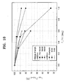
- Figures 10 and 11 show changes with respect to tilt by measuring the length and width of marks in order to compare mark shapes with respect to write power at a wavelength of 650 nm and at a wavelength of 400 nm, respectively.
- the figures show changes in length (L) and width (W) of recording mark with respect to write power (P w ) at a wavelength of 650 nm and at a wavelength of 400 nm when tilt occurs at a tilt of 0°.
- Figure 10 shows that as tilt increases, the length of a recording mark (L) decreases more at the wavelength of 400 nm than at the wavelength of 650 nm, and as write power (Pw) decreases, the length of the recording mark (L) decreases even at the same wavelength of 400 nm.
- Figure 11 shows that as tilt increases, the width of recording mark (W) decreases more at a wavelength of 400 nm than at a wavelength of 650 nm, and as write power (P w ) decreases, the width of the recording mark (W) decreases even at the same wavelength of 400 nm.
- the results in Figures 10 and 11 show that when the wavelength is 400 nm and tilt is 0.6°, recording with a write power of 5 mW to 7 mW causes a decrease in the length of a recording mark by about 72% to 88% and a decrease in the width of a recording mark by about 55% to 75%. That is, the results show that the size of a recording mark is compensated for with respect to the compensation of write power. Therefore, if a writing strategy which controls the recording waveform to a multi-waveform is more utilized for recording data applied to an optical disc system and compensation is performed by using additional erase power and additional write power, tilt can be reduced to a value which is close to zero.
- Figures 12A and 12B show tables of changes in the maximum temperature, and in the length and the width of a recording mark for each write power with respect to tilt.
- Table shown in Figure 12A shows the changes when the wavelength is 650 nm
- table shown in Figure 12B shows the changes when the wavelength is 400 nm.
- compensation can be performed using write time. For example, a recording mark can be compensated for in the length direction by adjusting write time. Therefore, by appropriately adjusting the power level and recording time, compensation is performed with respect to the amount of tilt, so that a mark with desired length and width can be recorded.
- Figure 13 shows changes in the recording mark length for different write times (T w ) with respect to tilt.
- the abscissa represents tilt
- the figure shows that as tilt increases, the length of a recording mark decreases more at a wavelength of 400 nm than at a wavelength of 650 nm, and that, as write time (T w ) decreases, the length of a recording mark (L) decreases even at the same wavelength of 400 nm.
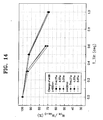
- Figure 14 shows changes in the recording mark width for different write times (T w ) with respect to tilt.
- the abscissa represents tilt
- the figure shows that as tilt increases, the width of a recording mark decreases more at a wavelength of 400 nm than at a wavelength of 650 nm, and that, as write time (T w ) decreases, the width of a recording mark (L) decreases even at the same wavelength of 400 nm.
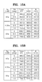
- Figures 15A and 15B show tables of changes in the maximum temperature, and in the length and the width of a recording mark for each write time (T w ) with respect to tilt.
- Table shown in Figure 15A shows the changes when the wavelength is 650 nm
- table shown in Figure 15B shows the changes when the wavelength is 400 nm.
- FIG 16 This defocus effect of the incident beam is shown in Figure 16, which illustrates changes in defocus with respect to the shape of mark (the length and width of a mark) for each write power when wavelengths 650 nm and 400 nm, respectively.
- the length and width of a recorded mark decrease as defocus increases, that is, as defocus increases from 0.25 ⁇ m to 0.5 ⁇ m, compared to a normal state where write power is 6mW.
- the same shape as the normal-state mark can be obtained when defocus is 0.25 ⁇ m and write power is 6.75mW, or when defocus is 0.5 ⁇ m and write power is 8mW. Therefore, as shown in Figure 17, a desired recording mark, that is a recording mark without defocus, can be recorded by using an amount of write power which compensates for the defocus.
- Figure 18 is a table showing the result of measuring the amount of shift of a recording location, and the length of a recording mark and width of a recording mark when tilt is zero, when tilt is 0.5°, and when tilt is 0.5°and defocus is 0.25 ⁇ m. Each value is obtained by increasing write power from the 6mW normal write power in steps of 1mW. When tilt is zero, a write power higher than 6mW is of no use, because the optimum write power is 6mW. When tilt is 0.5°, a write power higher than 8mW is of no use.
- Figure 19 illustrates changes in the length and width of a recording mark with respect to write power when tilt is 0.5°, and when tilt is 0.5° and defocus is 0.25 ⁇ m, based on the results in Figure 18.
- the figure shows that the difference (_1) between write power required for obtaining the width of a normal-state mark and write power required for obtaining the length of a normal-state mark when tilt is 0.5°, is almost the same as the difference (_2) between write power required for obtaining the width of a normal-state mark and write power required for obtaining the length of a normal-state mark when tilt is 0.5° and defocus is 0.25 ⁇ m.
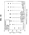
- Figure 20 illustrates the compensation effect by write time as well as write power when only tilt occurs (when tilt is 0.5°) based on the result in Figure 19.
- the figure shows that compensation can be effectively performed when compensation of the length of a mark is adjusted by write power and compensation of the width of a mark is adjusted by write time.
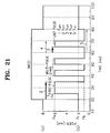
- the compensation is performed, using the ending time of the first pulse (T EFP ) and/or the starting time of the last pulse (T SLP ) of recording pattern shown in Figure 21B.
- T EFP ending time of the first pulse
- T SLP starting time of the last pulse
- NRZI non return to zero
- write pulses in Figure 21B are generated and then recorded on a disc.
- this NRZI data includes marks and spaces, and during spaces, the laser diode is off.
- a disc is a digital versatile disc (DVD)
- each mark of NRZI data having the length of 3T, 4T, ..., 14T (here, T is 1-bit length) is recorded only by changing the number of multi-pulses without changing the first pulse, the last pulse and a cooling pulse.
- the recording pattern according to a DVD specification includes the first pulse, a multi-pulse chain and the last pulse.
- the first rising edge of the first pulse of basic recording pulses occurs a predetermined time after the rising edge of a recording mark.
- the rising edge of the first pulse can be shifted before and after in units of 1 nanosecond (ns).
- the rising edge of the last pulse can be shifted also before and after in units of 1ns.
- a multi-pulse chain is divided into a plurality of short pulses to reduce accumulation of a heat at the latter part of a recording mark in order to prevent the occurrence of deformation in a recording mark.
- Numeral 1 of Figure 21B is the starting time of the first pulse (T SFP ), numeral 2 is the ending time of the first pulse (T EFP ), numeral 3 is the starting time of the last pulse (T SLP ), numeral 4 is the ending time of the last pulse (T ELP ), and numeral 5 is a cooling pulse period (T LC ).
- P w is write power (also referred to as peak write power)
- P r is read power
- P b bias power (also referred to as erase power).
- Figure 22 shows changes in the recording pattern shown in Figure 21 with respect to tilt, that is, changes in the recording location, the shift amount, the length and the width of a mark with respect to tilt and write power.
- the figure shows that as tilt increases, the amount by which the recording location of a mark is shifted increases and the length and the width of a mark decrease.
- the amount by which the recording location of a mark is shifted decreases and the length and the width of a mark increase.
- tilt when tilt is zero, a write power higher than 6mW is of no use, because the optimum write power is 6mW.
- tilt When tilt is 0.5°, a write power higher than 8mW is of no use.
- tilt is 1.0°, recording cannot be performed with a write power of 6mW or 7mW.
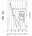
- Figure 23 shows the compensation effect of a recording pattern (the length and the width of a mark) by write power when tilt is 0.5°, based on the result in Figure 22.
- Figure 23 shows that when tilt occurs (when tilt is 5°), the length and the width of a mark increase as write power increases, and the length of a mark is effectively compensated for with write power. For example, when write power is 6mW, the length of a mark corresponds to 85% of the normal value and the width of a mark corresponds to 75% of the normal value. Therefore, in the same write power, compensating the length of a mark is more effective than compensating the width of a mark.
- Figure 24 illustrates the compensation effect of the recording pattern by write time as well as write power when tilt is 0.5°, based on the result in Figure 23.
- the figure shows that compensation for the length of a mark can be effectively adjusted by write power and compensation for the width of a mark can be effectively adjusted by write time.
- the compensation is performed using the ending time of the first pulse (T EFP ) and/or the starting time of the last pulse (T SLP ) of the recording pattern shown in Figure 21B.
- T EFP ending time of the first pulse
- T SLP starting time of the last pulse
- Compensation can be adaptively performed based on detected tilt, by storing in advance write power and/or write time, etc., for compensating for the shift amount of the recording pattern, and the length and the width of a mark with respect to tilt based on the result in Figure 22, in a memory.
- write power and/or write time, etc. for compensating for the shift amount of the recording pattern, and the length and the width of a mark according to the recording pattern (the length of a mark) of input data as well as tilt, can be stored.
- Figure 25 is the result of an experiment for compensation by write power with respect to detected defocus using 2.6GB DVD-RAM, and shows the same tendency as the result of simulation in Figure 16.
- the abscissa represents write power, while the ordinate represents the relative length and width of a mark.
- Figure 26 shows changes in the length and the width of a recording mark with respect to compensation by write power when a tilt of 1°occurs, using the same disc (2.6GB DVD-RAM) as the disc in Figure 25.
- the abscissa represents write power, while the ordinate represents the relative length and width of a mark. The figure shows that when tilt occurs, the length and the width of a mark are compensated for controlling write power.
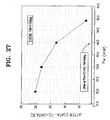
- Figure 27 shows the change in jitter with respect to power when tilt does not occur, and the change when a tilt of 1°occurs.
- the abscissa represents write power, while the ordinate represents jitter amount. In a normal state where tilt does not occur, jitter hardly occurs even though write power increases. But, when tilt occurs, jitter amount decreases as write power increases.
- the shift of beam by tilt is compensated for by shifting the entire recording pattern
- the length of a mark is compensated for by adjusting write power
- the width of a mark is compensated for by adjusting write time, and particularly by the ending time of the first pulse (T EFP ) and/or the starting time of the last pulse (T SLP ) in the recording pattern.
- the length of a mark is adjusted by write power
- the width of a mark can be adjusted by write power of multi-pulses located between the first pulse and the last pulse.
- FIG 28 is a flowchart of a method of compensating for tilt according to an embodiment of the present invention.
- step S102 it can be determined whether or not tilt is ⁇ ° by considering the margin of tilt ( ⁇ °).
- step S103 when detected tilt is not zero, the recording pattern of the write pulse is shifted in the direction for compensating for tilt. The length and the width of a recording mark are compensated for so that tilt is reduced down close to zero in step S104.
- compensation for the length of a mark is adjusted by write power
- compensation of the width of a mark is adjusted by write time, and particularly by the ending time of the first pulse (T EFP ) and/or the starting time of the last pulse (T SLP ) in the recording pattern.
- the length of a mark is adjusted by write power
- the width of a mark can be adjusted by write power of multi-pulses located between the first pulse and the last pulse.
- step S105 when tilt is zero in step S102, recording is performed by maintaining the power and write time required for recording, which are supplied to a laser diode, and when tilt is not zero in step S102, recording is performed by applying to a laser diode a write pulse, which has power and/or write time required for recording with respect to detected tilt supplied in the step S104.
- the required shift amount, write power and/or write time can be adaptively compensated for respect to detected tilt, by using a memory storing write power and/or write time for compensating for the shift amount of the recording pattern, and the length and the width of a mark with respect to tilt or the length of a mark in input data.
- Figure 29 is a flowchart of a method of compensating for tilt and defocus according to another embodiment of the present invention.
- step S201 tilt and/or defocus is detected, and in step S202, it is determined whether or not detected defocus is equal to or less than a predetermined margin ( ⁇ m).
- step S202 When the result in step S202 indicates that detected defocus is greater than a predetermined margin ( ⁇ m), write power is adjusted with respect to the detected defocus in step S203, and when the result in step S202 indicates that detected defocus is equal to or less than a predetermined margic ( ⁇ m), it is determined in step S204 whether or not detected tilt in step S201 is equal to or less than a predetermined margin ( ⁇ °) is determined in step S204.
- ⁇ m predetermined margin
- step S204 When the result in step S204 indicates that tilt is greater than a predetermined margin ( ⁇ °), the recording pattern of a write pulse is shifted in a direction which is opposite to the direction shifted due to tilt, with respect to detected tilt in step S205, and the length and the width of a recording mark is compensated for so that tilt is reduced down close to zero in step S206.
- step 206 compensation of the length of a mark is adjusted by write power, and compensation of the width of a mark is adjusted by write time, and particularly by the ending time of the first pulse (T EFP ) and/or the starting time of the last pulse (T SLP ) in the recording pattern.
- the length of a mark is adjusted by write power as described above, the width of a mark can be adjusted by the write power of multi-pulses located between the first pulse and the last pulse.
- step S207 when defocus is equal to or less than a predetermined margin (aum) and tilt is equal to or less than a predetermined margin ( ⁇ °), recording is performed by maintaining the power and write time required for recording, which are supplied to a laser diode, and otherwise, recording is performed by applying to a laser diode a write pulse, which has write power having write power with respect to defocus detected in step S203, or by applying to a laser diode a write pulse, which has power and/or time required for recording compensated with respect to detected tilt in step S206.
- write power for compensation with respect to defocus in step S203 and the required shift amount, write power and/or write time in steps S205 and S206 can be adaptively compensated for with respect to detected tilt and/or defocus, by using a memory storing write power and/or write time for compensating for the shift amount of the recording pattern, and the length and the width of a mark with respect to tilt or the length of a mark in input data.
- power and/or time, and the amount of shift required for recording which correspond to a case where defocus and tilt occur together, and a case where defocus or tilt occurs, respectively, can be stored.
- Figure 30 is a block diagram of an apparatus for compensating for tilt according to an embodiment of the present invention.
- Reference numeral 102 is an optical disc
- reference numeral 104 is a pick-up unit
- reference numeral 106 is a reproduction signal detector
- reference numeral 108 is a tilt detector
- reference numeral 110 is a recording compensator
- reference numeral 112 is a laser diode (LD) driver.
- LD laser diode
- the pick-up unit 104 which drives an optical disc 102, includes such mechanisms as an optical system, which includes an object lens 1, a half mirror 2, a collimator lens 3, a photo detector (PD), which detects an optical signal reflected from the disc 102 after dividing the signal, an LD, and, though not shown in the figure, an actuator for focusing and tracking.
- an optical system which includes an object lens 1, a half mirror 2, a collimator lens 3, a photo detector (PD), which detects an optical signal reflected from the disc 102 after dividing the signal, an LD, and, though not shown in the figure, an actuator for focusing and tracking.
- PD photo detector
- the laser diode wavelength of the pick-up unit 104 is equal to or less than approximately 430 nm (blue wavelength), that when the thickness of a disc substrate is equal to or greater than 0.3mm, the NA of an object lens is equal to or greater than 0.6, and that when the thickness of a disc substrate is equal to or less than 0.3mm, the NA of an object lens is equal to or greater than 0.7.
- the reproduction signal detector 106 detects a reproduction signal in the output signal of the PD.
- the tilt detector 108 detects tilt of an optical disc 102, using the reproduction signal supplied by the reproduction signal detector 106 or the output signal of the PD.
- the tilt detector 108 can be used only for detecting in tangential tilt.
- the recording compensator 110 generates a recording pulse earlier to compensate for the amount of shift due to tilt, which is detected by the tilt detector 108, in order to shift the starting point of a recording mark in the direction in which tilt is compensated.
- compensation of the length of a mark is adjusted by write power and compensation of the width of a mark is adjusted by write time.
- the width of a mark is compensated for by using the ending time of the first pulse (T EFP ) and/or the starting time of the last pulse (T SLP ) of the recording pattern.
- the length of a mark is adjusted by write power, as described above, and the width of a mark can be compensated for by adjusting write power of multi-pulses located between the first pulse and the last pulse.
- the recording compensator 110 can adaptively compensate for tilt detected in the tilt detector 106, by integrating a memory storing write power and/or write time for compensating for the shift amount of the recording pattern, and the length and the width of a mark with respect to tilt. Also, write power and/or write time, etc., for compensating for the shift amount of the recording pattern, and the length and the width of a mark with respect to the length of a mark of input data as well as tilt can be stored.
- the LD driver 112 performs recording on the optical disc 102 by the pick-up unit 104, by converting a write pulse signal into a current signal and making the current signal flow through the LD during write time, with respect to the power level of write pulse adjusted in the recording compensator 110. That is, when the laser diode is continuously turned on or off, heat is transferred to the optical disc and recording data is recorded as a recording mark.
- Figure 31 is a block diagram of an apparatus for compensating for tilt and defocus according to another embodiment of the present invention.
- Reference numeral 202 is an optical disc
- reference numeral 204 is a pick-up unit
- reference numeral 206 is a reproduction signal detector
- reference number 208 is a defocus/tilt detector
- reference numeral 210 is a recording compensator
- reference numeral 212 is a laser diode (LD) driver.
- LD laser diode
- the pick-up unit 204 which drives an optical disc 202, includes such mechanisms as an optical system, which includes an objective lens 11, a half mirror 12, a collimator lens 13, a photo detector (PD), which detects an optical signal reflected from the disc 202 after dividing the signal, a laser diode (LD), and, though not shown in the figure, an actuator for focusing and tracking.
- an optical system which includes an objective lens 11, a half mirror 12, a collimator lens 13, a photo detector (PD), which detects an optical signal reflected from the disc 202 after dividing the signal, a laser diode (LD), and, though not shown in the figure, an actuator for focusing and tracking.
- the laser diode wavelength of the pick-up unit 204 is equal to or less than approximately 430 nm (blue wavelength), and that when the thickness of a disc substrate is equal to or greater than 0.3mm, the NA of an object lens is equal to or greater than 0.6, and that when the thickness of a disc substrate is equal to or less than 0.3mm, the NA of an object lens is equal to or greater than 0.7.
- the reproduction signal detector 206 detects a reproduction signal in the output signal of the PD.
- the defocus/tilt detector 208 detects defocus/disc tilt, using the reproduction signal supplied by the reproduction signal detector 206 or the output signal of the PD.
- the tilt detector 208 can be used only for detecting tilt in tangential.
- the recording compensator 210 generates write pulse, which compensates write power due to detected defocus, when defocus is detected in the defocus/tilt detector 208, and generates a recording pulse earlier to compensate for the amount of shift due to the detected tilt, in order to shift the starting point of a recording mark when tilt is detected.
- compensation of the length of a mark is adjusted by write power and compensation of the width of a mark is adjusted by write time.
- the width of a mark is compensated for by using the ending time of the first pulse (T EFP ) and/or the starting time of the last pulse (T SLP ) of the recording pattern.
- the length of a mark is adjusted by write power, as described above, and the width of a mark can be compensated for by adjusting write power of multi-pulses located between the first pulse and the last pulse.
- the recording compensator 210 can adaptively compensate for tilt and/or defocus detected in the defocus/tilt detector 206, by integrating a memory storing compensation write power with respect to defocus, and write power and/or write time for compensating the shift amount of the recording pattern, and the length and the width of a mark with respect to tilt or the length of a mark in input data.
- the LD driver 212 performs recording on the optical disc 202 by the pick-up unit 204, by converting a write pulse signal into a current signal and making the current flow through the LD during write time, with respect to the power level of the write pulse adjusted in the recording compensator 210. That is, when the laser diode is continuously turned on or off, heat is transferred to the optical disc and recording data is recorded as a recording mark.
- the power (write power, erase power, etc.) level required for recording must be increased by a predetermined degree with respect to detected tilt and/or defocus. Also write time is adjusted. As a result, a temperature similar to that in a case, where tilt and/or defocus do not occur, can be obtained, and therefore, the desired size (length, width) of a mark can be recorded.
- the present invention since recording is compensated by adjusting the power level and/or recording time required for recording with respect to detected tilt and/or defocus, a mark having a desired size (length, width) can be recorded, and therefore, the present invention is appropriate for a high-density optical system.
Landscapes
- Physics & Mathematics (AREA)
- Optics & Photonics (AREA)
- Optical Recording Or Reproduction (AREA)
- Optical Head (AREA)
Abstract
Description
| Item | Effect | NA0.6 | NA0.65 | NA 0.85 | Effect in NA0.6 NA0.85 |
| Spot diameter (relative size) | λ/ | 1 | 0.93 | 0.70 | Capacity doubled |
| Focal depth (relative depth) | λ/ | 1 | 0.85 | 0.50 | Servo control bandwidth doubled |
| Disc tilt (relative margin amount) | λ/ | 1 | 0.79 | 0.35 | Strict disc tilt allowance |
| Disc thickness change (relative allowance) | λ/ | 1 | 0.73 | 0.25 | Strict thickness allowance in disc manufacturing |
Here, this NRZI data includes marks and spaces, and during spaces, the laser diode is off. When a disc is a digital versatile disc (DVD), each mark of NRZI data having the length of 3T, 4T, ..., 14T (here, T is 1-bit length) is recorded only by changing the number of multi-pulses without changing the first pulse, the last pulse and a cooling pulse.
The abscissa represents write power (Pw), while the ordinate shows the normalized value (L, Wpw, tilt=0.5/L, Wpw=6, tilt=0) of the length and the width of a recording mark with respect to write power when tilt is 5°, for write power of 6mW and a tilt of 0°.
Claims (40)
- A method of compensating for tilt of an optical recording medium , the method comprising the steps of:(a) detecting the tilt of the optical recording medium; and(b) compensating a recording signal having a predetermined recording pattern using a predetermined scheme with respect to the detected tilt.
- The method of claim 1, wherein the predetermined scheme adjusts an optical power level required for recording the recording signal.
- The method of claim 1 or 2, wherein the predetermined scheme adjusts time required for recording the recording signal.
- The method of claim 1, 2 or 3, wherein the step (b) further comprises the sub-steps of:(b1) shifting recording pattern with respect to detected tilt; and(b2) adjusting power and/or time required for recording with respect to the detected tilt in order to compensate the size of a recording mark corresponding to the recording signal.
- The method of claim 4, wherein in the step (b), the length of the mark is compensated for by adjusting the write power, and the width of the mark is compensated for by adjusting the write time.
- The method of claim 5, wherein the length of the mark is compensated by adjusting the write power, and the width of the mark is compensated for by adjusting the ending time of the first pulse and/or the starting time of the last pulse of the recording pattern.
- The method of claim 4, wherein in the step (b2), the length of the mark is compensated for by adjusting write power, and the width of the mark is compensated for by adjusting write power of a multi-pulse chain of recording pattern.
- A method for compensating input data for tilt of an optical recording medium, which records marks and spaces by write pulses having a predetermined recording pattern, the method comprising the steps of:(a) detecting the tilt of the optical recording medium; and(b) adaptively compensating the recording pattern with respect to the tilt detected in the step (a), using a memory storing power and/or time, etc., required for recording in order to compensate for the amount of shift of the recording pattern, and the length and the width of a mark with respect to tilt and/or the length of a mark.
- A method for compensating for defocus of an optical recording medium which can record and rewrite data, the method comprising the steps of:(a) detecting the defocus of the optical recording medium; and(b) performing compensating recording by a predetermined scheme with respect to the detected defocus.
- The method of claim 9, wherein the predetermined scheme adjust the level of optical power with respect to the detected defocus.
- A method of compensating for tilt and defocus of an optical recording medium, the method comprising the steps of:(a) detecting defocus of the optical recording medium;(b) compensating for write pulse having a predetermined recording pattern by a predetermined scheme with respect to detected defocus;(c) detecting the tilt of the optical recording medium; and(d) compensating write pulse having a predetermined recording pattern with respect to the detected tilt.
- The method of claim 11, wherein the predetermined scheme adjusts the level of optical power with respect to the detected defocus.
- The method of claim 11 or 12, wherein the step (d) further comprising the sub-steps of:(d1) shifting the recording pattern by an amount equal to the amount by which the recording pattern was shifted due to tilt in a direction which is opposite to the direction in which the recording pattern was shifted due to tilt, with respect to detected tilt; and(d2) adjusting the power and/or time required for recording with respect to the detected tilt in order to compensate for the size of a recording mark corresponding to the recording signal.
- The method of claim 13, wherein in the step (d2), the length of the mark is compensated for by adjusting write power, and the width of the mark is compensated for by adjusting write time.
- The method of claim 14, wherein the length of the mark is compensated for by adjusting write power, and the width of the mark is compensated for adjusting the ending time of the first pulse or the starting time of the last pulse of the recording pattern.
- The method of claim 13, wherein in the step (d2), the length of the mark is compensated for by adjusting write power, and the width of the mark is compensated for by adjusting write power of a multi-pulse chain of the recording pattern.
- A method for compensating input data for tilt and/or defocus of an optical recording medium, which records marks and spaces by write pulses having a predetermined recording pattern, the method comprising the steps of:(a) detecting the tilt and/or defocus of the optical recording medium; and(b) adaptively compensating the recording pattern with respect to the tilt and/or defocus detected in the step (a), using a memory storing compensation write power with respect to defocus, and power and/or time., etc., required for recording in order to compensate for the amount of shift of the recording pattern, and the length and the width of a mark with respect to tilt/the length of a mark.
- An apparatus for compensating for tilt which records and/or reproduces information on an optical recording medium, the apparatus comprising:a tilt detector (108) for detecting the tilt of an optical recording medium (102); anda recording compensator (112) for compensating the recording signal having a predetermined recording pattern, using a predetermined scheme with respect to tilt detected by the tilt detector (108).
- The apparatus for compensating for tilt of claim 18, wherein the predetermined scheme adjusts the level of optical power required for recording the recording signal.
- The apparatus for compensating tilt of claim 18 or 19, wherein the predetermined scheme adjusts time required for recording the recording signal.
- The apparatus for compensating tilt of claim 18, 19 or 20, wherein the recording compensator (110) shifts the recording pattern with respect to the detected tilt, and compensates for the length and the width of a mark with power and/or time required for recording.
- The apparatus for compensating for tilt of claim 21, wherein the length of the mark is compensated for by adjusting by power required for recording, and the width of the mark is compensated for by adjusting by time required for recording.
- The apparatus for compensating for tilt of claim 21, wherein the length of the mark is compensated for by adjusting write power, and the width of the mark is compensated for by adjusting the ending time of the first pulse/the starting pulse of the last pulse.
- The apparatus for compensating for tilt of claim 21, wherein the length of the mark is compensated for by adjusting write power, and the width of the mark is compensated for by adjusting power of a multi-pulse chain of the recording pattern.
- The apparatus for compensating tilt of claim 18, wherein the wavelength of a luminance source is equal to or less than approximately 430 nm of blue wavelength.
- The apparatus for compensating tilt of claim 18, wherein the thickness of the substrate of the optical recording medium is equal or greater than 0.3mm, and the numerical aperture of an object lens is equal to or greater than 0.6.
- The apparatus for compensating for tilt of claim 18, wherein the thickness of the substrate of the optical recording medium is equal to or less than 0.3mm, and the numerical aperture of an object lens is equal to or greater than 0.7.
- An apparatus for compensating input data for tilt of an optical recording medium, which records marks and spaces by write pulses having a predetermined recording pattern, the apparatus comprising:a tilt detector (108) for detecting the tilt of an optical recording medium; anda recording compensator (110) for adaptively compensating the recording pattern with respect to the tilt detected by the tilt detector (108), using a memory storing power and/or time, etc., required for recording in order to compensate for the amount of shift of the recording pattern, and the length and the width of a mark with respect to tilt and/or the length of a mark.
- An apparatus for compensating for tilt/defocus which records and/or reproduces information on an optical recording medium, the apparatus comprising:a tilt/defocus detector (208) for detecting the tilt and/or defocus of an optical recording medium (202); anda recording compensator (210) for compensating for the recording pulse having a predetermined recording pattern, using a predetermined scheme with respect to tilt and/or defocus detected by the tilt/defocus detector.
- The apparatus for compensating tilt/defocus of claim 29, wherein the predetermined scheme adjusts the level of optical power required for recording the recording pulse with respect to detected defocus.
- The apparatus for compensating tilt/defocus of claim 29 or 30, wherein the predetermined scheme adjusts power and/or time required for recording the recording pulse with respect to detected tilt.
- The apparatus for compensating tilt/defocus of claim 29, wherein after adjusting write power with respect to detected defocus, the recording compensator (210) generates write pulse earlier to compensate for the amount of shift with respect to detected tilt, and generates compensated write pulse having recording pattern in which power and/or time are adjusted in order to compensate the length and the width of a mark.
- The apparatus for compensating for tilt/defocus of claim 32, wherein the length of a mark is compensated for by adjusting power required for recording, and the width of a mark is compensated for by adjusting by time required for recording.
- The apparatus for compensating for tilt/defocus of claim 33, wherein the length of a mark is compensated for by adjusting write power, and the width of a mark is compensated for by adjusting the ending time of the first pulse/the starting time of the last pulse.
- The apparatus for compensating for tilt/defocus of claim 32, wherein the length of a mark is compensated for by adjusting write power, and the width of a mark is compensated for by adjusting power of a multi-pulse chain of recording pattern.
- The apparatus for compensating tilt/defocus of claim 29, wherein the wavelength of a luminance source is equal to or less than approximately 430 nm of blue wavelength.
- The apparatus for compensating tilt/defocus of claim 29, wherein the thickness of the substrate of the optical recording medium is equal or greater than 0.3mm, and the numerical aperture of an object lens is equal to or greater than 0.6.
- The apparatus for compensating tilt/defocus of claim 29, wherein the thickness of the substrate of the optical recording medium is equal to or less than 0.3mm, and the numerical aperture of an object lens is equal to or greater than 0.7.
- An apparatus for compensating input data for tilt and/or defocus of an optical recording medium, which records marks and spaces by write pulses having a predetermined recording pattern, the apparatus comprising:a tilt/defocus detector (208) for detecting the tilt/defocus of an optical recording medium (202); anda tilt/defocus compensator (208) for adaptively compensating the recording pattern with respect to the tilt and/or defocus detected by the tilt/defocus detector (208), using a memory storing compensation write power with respect to defocus, and power and/or time, etc., required for recording in order to compensate for the amount of shift of the recording pattern, and the length and the width of a mark with respect to tilt/the length of a mark.
- The apparatus for compensating tilt/defocus of claim 39, wherein in the memory, power and/or time, and the amount of shift required for recording, which correspond to a case where defocus and tilt occur together, and a case where defocus or tilt occurs, respectively, are stored.
Applications Claiming Priority (6)
| Application Number | Priority Date | Filing Date | Title |
|---|---|---|---|
| KR19990024297 | 1999-06-25 | ||
| KR9924297 | 1999-06-25 | ||
| KR9938399 | 1999-09-09 | ||
| KR1019990038399A KR100694023B1 (en) | 1999-09-09 | 1999-09-09 | Defocus / Tilt Compensation Method and Apparatus thereof |
| KR9938398 | 1999-09-09 | ||
| KR1019990038398A KR100694022B1 (en) | 1999-06-25 | 1999-09-09 | Tilt compensation method and apparatus |
Publications (3)
| Publication Number | Publication Date |
|---|---|
| EP1063644A2 true EP1063644A2 (en) | 2000-12-27 |
| EP1063644A3 EP1063644A3 (en) | 2003-01-08 |
| EP1063644B1 EP1063644B1 (en) | 2005-08-17 |
Family
ID=27350004
Family Applications (1)
| Application Number | Title | Priority Date | Filing Date |
|---|---|---|---|
| EP00305348A Expired - Lifetime EP1063644B1 (en) | 1999-06-25 | 2000-06-23 | Method of compensating for tilt and/or defocus and apparatus therefor |
Country Status (6)
| Country | Link |
|---|---|
| US (2) | US6940797B1 (en) |
| EP (1) | EP1063644B1 (en) |
| JP (1) | JP2001023174A (en) |
| CN (1) | CN1200412C (en) |
| DE (1) | DE60021960T2 (en) |
| TW (1) | TW567481B (en) |
Cited By (2)
| Publication number | Priority date | Publication date | Assignee | Title |
|---|---|---|---|---|
| WO2003050804A1 (en) * | 2001-12-12 | 2003-06-19 | Tdk Corporation | Optical recording medium recording/reproducing method |
| EP1359572A3 (en) * | 2002-05-02 | 2005-05-11 | Pioneer Corporation | Information recording and reproducing apparatus and information recording method |
Families Citing this family (15)
| Publication number | Priority date | Publication date | Assignee | Title |
|---|---|---|---|---|
| JP2001023174A (en) * | 1999-06-25 | 2001-01-26 | Samsung Electronics Co Ltd | Method and apparatus for compensating tilt and / or defocus |
| US20010015939A1 (en) * | 2000-02-08 | 2001-08-23 | Asahi Kogaku Kogyo Kabushiki Kaisha | Objective lens for optical pick-up |
| JP2002361692A (en) * | 2001-06-12 | 2002-12-18 | Pioneer Electronic Corp | Disc molding apparatus and method for manufacturing disc substrate |
| JP2003001681A (en) * | 2001-06-21 | 2003-01-08 | Pioneer Electronic Corp | Unit for releasing disc substrate and method for manufacturing disc |
| KR100472469B1 (en) * | 2002-08-17 | 2005-03-10 | 삼성전자주식회사 | Method for correcting tilt in the disc drive and method thereof |
| CN100446096C (en) * | 2002-09-17 | 2008-12-24 | 联发科技股份有限公司 | Optical disk data access device and optical head inclination angle correction and adjustment method |
| JP4205961B2 (en) * | 2003-01-28 | 2009-01-07 | 株式会社日立エルジーデータストレージ | Optical disc recording / reproducing apparatus and recording method |
| KR20050052606A (en) * | 2003-11-28 | 2005-06-03 | 삼성전자주식회사 | Information storage medium, method and apparatus for reproducing of information recorded in the same |
| JP4569306B2 (en) * | 2005-02-02 | 2010-10-27 | 船井電機株式会社 | Optical disc apparatus and defocus adjustment method |
| JP2007035087A (en) * | 2005-07-22 | 2007-02-08 | Pulstec Industrial Co Ltd | Identification information recording apparatus and identification information recording method for optical disc |
| JP2009289318A (en) * | 2008-05-28 | 2009-12-10 | Canon Inc | Optical recording and reproducing apparatus |
| JP5311881B2 (en) * | 2008-05-28 | 2013-10-09 | キヤノン株式会社 | Optical recording / reproducing device |
| KR20100135048A (en) * | 2009-06-16 | 2010-12-24 | 삼성전자주식회사 | Encoder with tilt compensation, servo track recorder for hard disk drive and hard disk drive using it |
| JP2012069190A (en) * | 2010-09-22 | 2012-04-05 | Sony Corp | Reproducing device, and optical path length servo control method |
| US8971163B2 (en) | 2011-01-07 | 2015-03-03 | Mitsubishi Electric Corporation | Optical disc device, optical disc and testing method of optical disc |
Family Cites Families (45)
| Publication number | Priority date | Publication date | Assignee | Title |
|---|---|---|---|---|
| US4358774A (en) * | 1980-07-14 | 1982-11-09 | Discovision Associates | Apparatus and method for controlling focus in a recording system |
| FR2546325B1 (en) * | 1983-05-20 | 1988-07-08 | Thomson Csf | OPTICAL POWER CALIBRATION METHOD AND DEVICE APPLIED TO AN OPTICAL DISC FOR DATA RECORDING |
| JPS6020326A (en) | 1983-07-14 | 1985-02-01 | Olympus Optical Co Ltd | Optical disk device |
| JPS6066341A (en) * | 1983-09-20 | 1985-04-16 | Olympus Optical Co Ltd | Recording and reproducing device of information |
| JPS60132616U (en) * | 1984-02-13 | 1985-09-04 | パイオニア株式会社 | recording device |
| US4637712A (en) * | 1984-11-21 | 1987-01-20 | Hasco International, Inc. | System for package photoprinting |
| JP2528632B2 (en) | 1985-07-04 | 1996-08-28 | 松下電器産業株式会社 | Signal recorder |
| JP2615650B2 (en) | 1987-08-17 | 1997-06-04 | 松下電器産業株式会社 | Recording method for optical information recording member |
| JPS6446231U (en) | 1987-09-17 | 1989-03-22 | ||
| JP2677325B2 (en) | 1987-12-07 | 1997-11-17 | 株式会社日立製作所 | How information is recorded |
| JPH02230515A (en) * | 1989-03-03 | 1990-09-12 | Sony Corp | Optical recording and reproducing device |
| JPH0810490B2 (en) | 1989-03-20 | 1996-01-31 | 富士通株式会社 | Optical disk information writing control method and apparatus therefor |
| JPH0414422A (en) | 1990-05-08 | 1992-01-20 | Sekisui Chem Co Ltd | Method for controlling warpage quantity of resin molded product |
| US5449590A (en) * | 1991-06-04 | 1995-09-12 | International Business Machines Corporation | Multiple data surface optical data storage system |
| JP2993533B2 (en) | 1991-08-26 | 1999-12-20 | 沖電気工業株式会社 | Information processing device and character recognition device |
| US5838646A (en) * | 1991-09-11 | 1998-11-17 | Sony Corporation | Optical disk having a protective layer of specified thickness relative to the numerical aperture of the objective lens |
| US5383175A (en) | 1992-12-17 | 1995-01-17 | International Business Machines Corporation | Laser power control with defocusing offset during data recording |
| JP2857002B2 (en) * | 1993-01-07 | 1999-02-10 | シャープ株式会社 | Magneto-optical storage device |
| US5703855A (en) * | 1993-04-06 | 1997-12-30 | Hitachi, Ltd. | Optical disk apparatus and recording and reading method for an optical disk using the same |
| JPH06295458A (en) * | 1993-04-09 | 1994-10-21 | Pioneer Electron Corp | Optical information recording and reproducing device |
| US5446716A (en) * | 1994-01-10 | 1995-08-29 | Eastman Kodak Company | Laser power control in an optical recording system to compensate for multiple system degradations |
| US5495466A (en) * | 1994-01-10 | 1996-02-27 | Eastman Kodak Company | Write verification in an optical recording system by sensing mark formation while writing |
| US5699342A (en) * | 1994-02-07 | 1997-12-16 | Mitsubishi Denki Kabushiki Kaisha | Method of and device for recording and playing back an optical disk having a test playback region utilizing pits of minimum size for controlling the power of the laser |
| US5450383A (en) * | 1994-05-26 | 1995-09-12 | International Business Machines Corporation | Monitoring and adjusting laser write power in an optical disk recorder using pulse-width modulated power level checking signals |
| JPH0868933A (en) * | 1994-08-31 | 1996-03-12 | Nikon Corp | Automatic focusing device |
| US5544268A (en) * | 1994-09-09 | 1996-08-06 | Deacon Research | Display panel with electrically-controlled waveguide-routing |
| EP0725397B1 (en) * | 1995-01-31 | 1999-09-15 | Canon Kabushiki Kaisha | Write test method for pit edge recording method and optical information recording/reproducing apparatus utilizing the same test method |
| US5675568A (en) * | 1996-01-16 | 1997-10-07 | Eastman Kodak Company | Laser power control in an optical recording system to compensate for variations in mark length resulting from a wobbled groove |
| JPH09231569A (en) | 1996-02-23 | 1997-09-05 | Ricoh Co Ltd | Optical disc master manufacturing method |
| US5903537A (en) * | 1997-04-07 | 1999-05-11 | Eastman Kodak Company | Direct read during mark formation for laser power correction |
| JPH10289461A (en) * | 1997-04-15 | 1998-10-27 | Hitachi Ltd | Information recording / reproducing apparatus and information recording method |
| JP3211002B2 (en) * | 1997-04-24 | 2001-09-25 | 富士通株式会社 | Optical recording medium, tilt detector, optical disk device, tilt detection method, and tilt correction method |
| JP3579214B2 (en) * | 1997-06-24 | 2004-10-20 | 富士通株式会社 | Optical storage |
| KR19990031138A (en) | 1997-10-09 | 1999-05-06 | 김덕중 | Multi-wavelength optical pickup device |
| JPH11144279A (en) | 1997-11-05 | 1999-05-28 | Toshiba Corp | Optical disk drive |
| JP3788684B2 (en) * | 1998-03-06 | 2006-06-21 | パイオニア株式会社 | Waveform equalizer and data reproducing apparatus using the same |
| JPH11273115A (en) * | 1998-03-19 | 1999-10-08 | Hitachi Ltd | Optical information recording / reproducing device |
| US6304366B1 (en) * | 1998-04-02 | 2001-10-16 | Michael Scalora | Photonic signal frequency conversion using a photonic band gap structure |
| KR100278786B1 (en) * | 1998-06-18 | 2001-01-15 | 구자홍 | Optical Recording Medium and Optical Recording/Reproducing Method and Apparatus |
| CN1233824A (en) * | 1998-04-24 | 1999-11-03 | 松下电器产业株式会社 | Optical disc recording and reproducing method and optical disc recording and reproducing device |
| JP3600016B2 (en) * | 1998-06-12 | 2004-12-08 | パイオニア株式会社 | Optical information recording / reproducing device and optical pickup |
| JP3734621B2 (en) * | 1998-07-03 | 2006-01-11 | 株式会社リコー | Optical information recording method and apparatus |
| JP3076033B1 (en) * | 1998-09-14 | 2000-08-14 | 松下電器産業株式会社 | Optical information recording / reproducing apparatus and information recording medium |
| JP3773677B2 (en) * | 1998-10-30 | 2006-05-10 | パイオニア株式会社 | Optical recording medium recording apparatus |
| JP2001023174A (en) * | 1999-06-25 | 2001-01-26 | Samsung Electronics Co Ltd | Method and apparatus for compensating tilt and / or defocus |
-
2000
- 2000-06-23 JP JP2000190119A patent/JP2001023174A/en active Pending
- 2000-06-23 DE DE60021960T patent/DE60021960T2/en not_active Expired - Lifetime
- 2000-06-23 EP EP00305348A patent/EP1063644B1/en not_active Expired - Lifetime
- 2000-06-25 CN CNB00122591XA patent/CN1200412C/en not_active Expired - Fee Related
- 2000-06-26 US US09/603,204 patent/US6940797B1/en not_active Expired - Fee Related
- 2000-09-20 TW TW089112234A patent/TW567481B/en not_active IP Right Cessation
-
2005
- 2005-05-10 US US11/125,074 patent/US7379404B2/en not_active Expired - Fee Related
Cited By (3)
| Publication number | Priority date | Publication date | Assignee | Title |
|---|---|---|---|---|
| WO2003050804A1 (en) * | 2001-12-12 | 2003-06-19 | Tdk Corporation | Optical recording medium recording/reproducing method |
| US7110335B2 (en) | 2001-12-12 | 2006-09-19 | Tdk Corporation | Recording and reproducing method for optical recording medium and optical recording medium |
| EP1359572A3 (en) * | 2002-05-02 | 2005-05-11 | Pioneer Corporation | Information recording and reproducing apparatus and information recording method |
Also Published As
| Publication number | Publication date |
|---|---|
| EP1063644A3 (en) | 2003-01-08 |
| JP2001023174A (en) | 2001-01-26 |
| US7379404B2 (en) | 2008-05-27 |
| US6940797B1 (en) | 2005-09-06 |
| TW567481B (en) | 2003-12-21 |
| EP1063644B1 (en) | 2005-08-17 |
| CN1200412C (en) | 2005-05-04 |
| DE60021960T2 (en) | 2006-03-23 |
| CN1281215A (en) | 2001-01-24 |
| US20050201226A1 (en) | 2005-09-15 |
| DE60021960D1 (en) | 2005-09-22 |
Similar Documents
| Publication | Publication Date | Title |
|---|---|---|
| EP1063644B1 (en) | Method of compensating for tilt and/or defocus and apparatus therefor | |
| US8000177B2 (en) | Reading device and reading method for an optical data recording medium | |
| EP1548711A1 (en) | Recording condition setting method and information recorder using same | |
| CN101840713B (en) | Method and apparatus for recording and reproducing optical information, and recording medium | |
| US6560178B2 (en) | Tilt compensation method and apparatus therefor | |
| CN101114467A (en) | Recording policy determination method, optical disc recording method, optical disc and optical disc device | |
| US20090109816A1 (en) | Optical disc apparatus and optical disc processing method | |
| US7359298B2 (en) | Optical pickup device for writing information to an optical disk | |
| KR100694022B1 (en) | Tilt compensation method and apparatus | |
| KR100694023B1 (en) | Defocus / Tilt Compensation Method and Apparatus thereof | |
| KR20050012282A (en) | Method and device for recording marks representing data in an information layer of an optical record carrier | |
| Narumi et al. | Rewritable dual-layer phase-change optical disk with a balanced transmittance structure | |
| US7492693B2 (en) | Optical recording/reproducing apparatus with transmission amount variation unit | |
| US7095703B2 (en) | Apparatus and method for recording mark | |
| JP2778428B2 (en) | Optical disk drive | |
| EP1437720A1 (en) | Optical recording medium | |
| US20050286383A1 (en) | Method of recording data on optical recording media and optical recording device | |
| US20090109815A1 (en) | Optical disc device and optical disc processing method | |
| MX2008015443A (en) | Method and device for retrieving information from an optical record carrier at various reading speeds. | |
| CN102419986A (en) | Optical disc apparatus, information recording method, and optical disc | |
| JP2009301653A (en) | Optical head apparatus and information recording/reproducing apparatus using the same | |
| JP2003233928A (en) | Optical pickup device and its manufacturing method | |
| CN101213599A (en) | Track writing with radial error offset correction | |
| JPH11339270A (en) | Information reproducing device for optical information recording medium | |
| JP2013030266A (en) | Optical information recording and reproduction method |
Legal Events
| Date | Code | Title | Description |
|---|---|---|---|
| PUAI | Public reference made under article 153(3) epc to a published international application that has entered the european phase |
Free format text: ORIGINAL CODE: 0009012 |
|
| 17P | Request for examination filed |
Effective date: 20000711 |
|
| AK | Designated contracting states |
Kind code of ref document: A2 Designated state(s): AT BE CH CY DE DK ES FI FR GB GR IE IT LI LU MC NL PT SE |
|
| AX | Request for extension of the european patent |
Free format text: AL;LT;LV;MK;RO;SI |
|
| RIN1 | Information on inventor provided before grant (corrected) |
Inventor name: KO, JUNG-WAN Inventor name: PARK, IN-SIK Inventor name: LEE, KYUNG-GEUN Inventor name: JOO, SUNG-SIN, C/O SAMSUNG ELECTRONICS CO. LTD. |
|
| PUAL | Search report despatched |
Free format text: ORIGINAL CODE: 0009013 |
|
| AK | Designated contracting states |
Kind code of ref document: A3 Designated state(s): AT BE CH CY DE DK ES FI FR GB GR IE IT LI LU MC NL PT SE |
|
| AX | Request for extension of the european patent |
Free format text: AL;LT;LV;MK;RO;SI |
|
| 17Q | First examination report despatched |
Effective date: 20030723 |
|
| AKX | Designation fees paid |
Designated state(s): DE FR GB NL |
|
| GRAP | Despatch of communication of intention to grant a patent |
Free format text: ORIGINAL CODE: EPIDOSNIGR1 |
|
| GRAS | Grant fee paid |
Free format text: ORIGINAL CODE: EPIDOSNIGR3 |
|
| GRAA | (expected) grant |
Free format text: ORIGINAL CODE: 0009210 |
|
| AK | Designated contracting states |
Kind code of ref document: B1 Designated state(s): DE FR GB NL |
|
| REG | Reference to a national code |
Ref country code: GB Ref legal event code: FG4D |
|
| REF | Corresponds to: |
Ref document number: 60021960 Country of ref document: DE Date of ref document: 20050922 Kind code of ref document: P |
|
| ET | Fr: translation filed | ||
| PLBE | No opposition filed within time limit |
Free format text: ORIGINAL CODE: 0009261 |
|
| STAA | Information on the status of an ep patent application or granted ep patent |
Free format text: STATUS: NO OPPOSITION FILED WITHIN TIME LIMIT |
|
| 26N | No opposition filed |
Effective date: 20060518 |
|
| PGFP | Annual fee paid to national office [announced via postgrant information from national office to epo] |
Ref country code: GB Payment date: 20140522 Year of fee payment: 15 |
|
| PGFP | Annual fee paid to national office [announced via postgrant information from national office to epo] |
Ref country code: NL Payment date: 20140521 Year of fee payment: 15 Ref country code: DE Payment date: 20140523 Year of fee payment: 15 |
|
| PGFP | Annual fee paid to national office [announced via postgrant information from national office to epo] |
Ref country code: FR Payment date: 20140522 Year of fee payment: 15 |
|
| REG | Reference to a national code |
Ref country code: DE Ref legal event code: R119 Ref document number: 60021960 Country of ref document: DE |
|
| GBPC | Gb: european patent ceased through non-payment of renewal fee |
Effective date: 20150623 |
|
| REG | Reference to a national code |
Ref country code: NL Ref legal event code: MM Effective date: 20150701 |
|
| REG | Reference to a national code |
Ref country code: FR Ref legal event code: ST Effective date: 20160229 |
|
| PG25 | Lapsed in a contracting state [announced via postgrant information from national office to epo] |
Ref country code: NL Free format text: LAPSE BECAUSE OF NON-PAYMENT OF DUE FEES Effective date: 20150701 Ref country code: GB Free format text: LAPSE BECAUSE OF NON-PAYMENT OF DUE FEES Effective date: 20150623 Ref country code: DE Free format text: LAPSE BECAUSE OF NON-PAYMENT OF DUE FEES Effective date: 20160101 |
|
| PG25 | Lapsed in a contracting state [announced via postgrant information from national office to epo] |
Ref country code: FR Free format text: LAPSE BECAUSE OF NON-PAYMENT OF DUE FEES Effective date: 20150630 |