EP1063552A1 - Optical scanner - Google Patents
Optical scanner Download PDFInfo
- Publication number
- EP1063552A1 EP1063552A1 EP00113358A EP00113358A EP1063552A1 EP 1063552 A1 EP1063552 A1 EP 1063552A1 EP 00113358 A EP00113358 A EP 00113358A EP 00113358 A EP00113358 A EP 00113358A EP 1063552 A1 EP1063552 A1 EP 1063552A1
- Authority
- EP
- European Patent Office
- Prior art keywords
- light beams
- optics
- scanning direction
- scanned
- plane
- Prior art date
- Legal status (The legal status is an assumption and is not a legal conclusion. Google has not performed a legal analysis and makes no representation as to the accuracy of the status listed.)
- Ceased
Links
- 230000003287 optical effect Effects 0.000 title claims abstract description 33
- 238000007493 shaping process Methods 0.000 claims abstract description 25
- 239000004065 semiconductor Substances 0.000 description 4
- 230000001419 dependent effect Effects 0.000 description 1
- 238000012986 modification Methods 0.000 description 1
- 230000004048 modification Effects 0.000 description 1
Images

Classifications
-
- G—PHYSICS
- G02—OPTICS
- G02B—OPTICAL ELEMENTS, SYSTEMS OR APPARATUS
- G02B26/00—Optical devices or arrangements for the control of light using movable or deformable optical elements
- G02B26/08—Optical devices or arrangements for the control of light using movable or deformable optical elements for controlling the direction of light
- G02B26/10—Scanning systems
- G02B26/12—Scanning systems using multifaceted mirrors
- G02B26/123—Multibeam scanners, e.g. using multiple light sources or beam splitters
-
- G—PHYSICS
- G02—OPTICS
- G02B—OPTICAL ELEMENTS, SYSTEMS OR APPARATUS
- G02B26/00—Optical devices or arrangements for the control of light using movable or deformable optical elements
- G02B26/08—Optical devices or arrangements for the control of light using movable or deformable optical elements for controlling the direction of light
- G02B26/10—Scanning systems
- G02B26/12—Scanning systems using multifaceted mirrors
- G02B26/124—Details of the optical system between the light source and the polygonal mirror
Definitions
- the present invention relates to an optical scanner.
- a problem with the multi-beam optical scanner is that if the position of the plane to be scanned is shifted along the optical axis, the distance between adjacent light beams varies not only in a secondary scanning direction but also in a primary scanning direction.
- the variation in distance between adjacent light beams in the primary scanning direction will cause a straight line crossing the scanning lines to be imaged as a jagged line, and thus a smooth straight line cannot be represented.
- This invention relates to a multi beam scanner.
- the present invention has as an object providing a multi-beam optical scanner which is free from the problem of variations in the distance between adjacent light beams in a primary scanning direction notwithstanding a shift of the plane to be scanned along the optical axis.
- This object of the present invention can be attained by an optical scanner that deflects a plurality of adjacent light beams across a plane to be scanned in a primary scanning direction and which causes relative movement of the plane to be scanned in a secondary scanning direction perpendicular to the primary scanning direction, wherein said plurality of light beams are allowed to be incident substantially parallel to each other on the plane to be scanned in the primary scanning direction.
- the object can also be attained by another optical scanner comprising shaping optics by which a plurality of light beams issued from mutually adjacent light emitting portions are shaped to be substantially parallel at least in a primary scanning direction, a deflector having reflecting faces that reflect and deflect said plurality of light beams and scanning optics by which the plurality of light beams reflected and deflected by the reflecting faces of said deflector are scanned across the plane to be scanned as a plurality of adjacent beam spots, wherein said plurality of light beams cross one another near the front focus of said scanning optics in the primary scanning direction.
- Another optical scanner comprising shaping optics by which a plurality of light beams issued from mutually adjacent light emitting portions are shaped to be substantially parallel at least in a primary scanning direction, a deflector having reflecting faces that reflect and deflect said plurality of light beams and scanning optics by which the plurality of light beams reflected and deflected by the reflecting faces of said deflector are scanned across the plane to be scanned as a plurality of adjacent beam spots, wherein the distance from the rear principal plane of said shaping optics to the front principal plane of said scanning optics is expressed by f 1 + f 2 , where f 1 is the focal length of said shaping optics in the primary scanning direction and f 2 is the focal length of said scanning optics.
- yet another optical scanner comprising shaping optics by which a plurality of light beams issued from mutually adjacent light emitting portions are shaped to be substantially parallel at least in a primary scanning direction, a deflector having reflecting faces that reflect and deflect said plurality of light beams and scanning optics by which the plurality of light beams reflected and deflected by the reflecting faces of said deflector are scanned across the plane to be scanned as a plurality of adjacent beam spots, wherein said shaping optics and said scanning optics compose a focal optics in the primary scanning direction.
- any one of these optical scanners is desirably adapted to be such that the plurality of light beams are allowed to be incident substantially parallel to each other on the plane to be scanned in the secondary scanning direction.
- a plurality of light beams are allowed to be incident substantially parallel to each other on the plane to be scanned in the primary scanning direction. Therefore, the distance between adjacent light beams does not change in the primary scanning direction even if the plane to be scanned shifts along the optical axis.
- a plurality of light beams may be arranged either one-dimensionally or two-dimensionally at an angle with respect to scanning lines and yet lines crossing the scanning lines can be drawn as smooth lines in an accurate and consistent manner.
- optical scanner of the invention is described below with reference to the preferred embodiments.
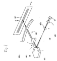
- Fig. 1 is a perspective view of the optics in the optical scanner.
- Four light beams are issued from a semiconductor laser 41 having four light-emitting portions arranged at an angle with respect to a primary scanning direction P (in Figs. 2 and 3 which will be discussed later, only two light-emitting portions 41 1 and 41 2 are shown).
- the issued four light beams pass through a collimator lens 42 1 so that each of the beams is collimated as a parallel beam in both the primary scanning direction P and a secondary scanning direction S.
- the collimated light beams pass through a cylindrical lens 42 2 having a positive refractive power only in the secondary scanning direction S so that they are converged only in the secondary scanning direction S.
- the light beams are incident on a reflecting face 45 of a rotating polygonal mirror 44 such that each of the light beams is parallel in the primary scanning direction P but the beam spot images are focussed on or near the reflecting face 45 in the secondary scanning direction S.
- the light beams reflected and deflected by the reflecting face 45 pass through a first scanning lens 46 1 and a second scanning lens 46 2 so that four beam spots appear on a plane 48 to be scanned, which are aligned at an angle with respect to the primary scanning direction P to form four scanning lines.
- the first scanning lens 46 1 is a lens of axial symmetry having a positive refractive power.
- the second scanning lens 46 2 is elongated in the primary scanning direction P; it has a positive refractive power in the secondary scanning direction S but has no refractive power in the primary scanning direction P.
- the reflecting face 45 and the plane 48 to be scanned have a conjugated relationship in the secondary scanning direction S so that the beam spot images on or near the reflecting face 45 are focussed on the plane 48 to be scanned.
- the parallel light beams reflected from the reflecting face 45 are converged and focussed on the plane 48 to be scanned.
- the optics under consideration is of a conjugate type capable of correcting tilting.
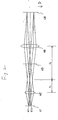
- the optical path in the optics shown in Fig. 1 is developed in the primary scanning direction as shown in Fig. 2 and developed in the secondary scanning direction as shown in Fig. 3a.
- the collimator lens 42 1 and the cylindrical lens 42 2 are illustrated as shaping optics 42 that is a single lens having different focal lengths in the primary and secondary scanning directions.
- the first scanning lens 46 1 and the second scanning lens 46 2 are illustrated as scanning optics 46 that is a single lens having different focal lengths in the primary and secondary scanning directions.
- the semiconductor laser 41 having two light-emitting portions 41 1 and 41 2 is located at the front focal plane of the shaping optics 42.
- the focal length of the shaping optics 42 in the primary scanning direction is written as f 1 and the focal length of the scanning optics 46 in the primary scanning direction as f 2
- the principal points of the shaping optics 42 and the scanning optics 46 are spaced apart by f 1 + f 2 so that the rear focal point of the shaping optics 42 coincides with the front focal point of the scanning optics 46.
- the plane 48 to be scanned substantially coincides with the rear focal plane of the scanning optics 46.
- the semiconductor laser 41 having two light-emitting portions 41 1 and 41 2 is located away from the front focal point of the shaping optics 42 and located at a conjugated position relative to the reflecting face 45 of the rotating polygonal mirror 41 with respect to the shaping optics 42 so that the images of the light-emitting portions 41 1 and 41 2 are focussed on or near the reflecting face 45.
- the reflecting face 45 is located at a conjugated position relative to the plane 48 to be scanned with respect to the scanning optics 46 so that the images of the light-emitting portions 41 1 and 41 2 are focussed on the plane 48 to be scanned as secondary images.
- the shaping optics 42 and the scanning optics 46 compose afocal optics in the primary scanning direction, so that the principal rays of the light beams issued from the light-emitting portions 41 1 and 41 2 cross each other at a point near the front focal point of the scanning optics 46 and are incident on the plane 48 to be scanned such that axes of light beams are substantially parallel to each other. Therefore, even if the plane 48 to be scanned shifts in the optical axis direction when the polygonal mirror 44 rotates clockwise (as indicated by the arrow in Fig.
- the layout may be modified as shown in Fig.
- a relay lens 43 having a positive power only in the secondary scanning direction is provided between the shaping optics 42 and the reflecting face 45 of the rotating polygonal mirror 44 to ensure that the semiconductor laser 41 is allowed to have a conjugate relationship with the reflecting face 45 of the polygonal mirror 44 by the combination of the shaping optics 42 and the relay lens 43 so that the images of the light-emitting portions 41 1 and 41 2 are focussed on or near the reflecting face 45 and the principal rays of the light beams cross each other at a point near the front focal point of the scanning optics 46.
- the principal rays of the light beams are incident on the plane 48 to be scanned to be substantially parallel to each other in the secondary scanning direction as well as in the primary scanning direction. Even if the plane 48 to be scanned shifts in the optical axis direction, the distance between adjacent light beams will not change in the secondary scanning direction and smooth lines can be drawn in a more accurate and consistent manner.
- the optical scanner of the invention is adapted to be such that a plurality of light beams are allowed to be incident substantially parallel to each other on a plane to be scanned in a primary scanning direction. Therefore, the distance between adjacent light beams will not change in the primary scanning direction even if the plane to be scanned shifts along the optical axis; as a result, lines crossing the scanning lines can be drawn as smooth lines in an accurate and consistent manner even if a plurality of light beams are arranged either one-dimensionally or two-dimensionally at an angle with respect to the scanning lines.
Landscapes
- Physics & Mathematics (AREA)
- General Physics & Mathematics (AREA)
- Optics & Photonics (AREA)
- Mechanical Optical Scanning Systems (AREA)
- Laser Beam Printer (AREA)
- Facsimile Scanning Arrangements (AREA)
Abstract
A multi-beam optical scanner includes shaping optics (42) by
which a plurality of light beams issued from light emitting
potions (411, 412) are shaped to be substantially parallel in a
primary scanning direction, a deflector having reflecting faces
(45) that reflect and deflect the plurality of light beams and
scanning optics (46) by which the plurality of light beams
reflected and deflected by the reflecting faces (45) are
scanned across a plane (48) to be scanned as a plurality of
adjacent beam spots, wherein the distance from the rear
principal plane of the shaping optics (42) to the front
principal plane of the scanning optics 46 is expressed by f1 +
f2 where f1 and f2 are the focal lengths of the shaping optics
(42) and the scanning optics (46), respectively, in the primary
scanning direction.
Description
- The present invention relates to an optical scanner.
- In a multi-beam optical scanner, the same plane is scanned with a plurality of light beams that are incident on it simultaneously. In order to prevent undesired phenomena such as a variation in distance between adjacent beams on the plane being scanned, it has been proposed in Unexamined Published Japanese Patent Application (kokai) Nos. 274151/1997 and 209596/1995 that optics be provided in such a way that a plurality of light beams are incident on the plane to be scanned parallel to each other in a secondary scanning direction.
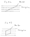
- A problem with the multi-beam optical scanner is that if the position of the plane to be scanned is shifted along the optical axis, the distance between adjacent light beams varies not only in a secondary scanning direction but also in a primary scanning direction. In particular, in a case where a plurality of light beams are arranged at an angle with respect to scanning lines either one-dimensionally (as shown in Fig. 4a) or two-dimensionally (as shown in Fig. 4b), the variation in distance between adjacent light beams in the primary scanning direction will cause a straight line crossing the scanning lines to be imaged as a jagged line, and thus a smooth straight line cannot be represented.
- It is therefor the object of the present invention to provide a scanner which overcomes the drawbacks of the prior art products. This object is solved by the scanners according to
independent claims - This invention relates to a multi beam scanner.
- More particular, the present invention has as an object providing a multi-beam optical scanner which is free from the problem of variations in the distance between adjacent light beams in a primary scanning direction notwithstanding a shift of the plane to be scanned along the optical axis.
- This object of the present invention can be attained by an optical scanner that deflects a plurality of adjacent light beams across a plane to be scanned in a primary scanning direction and which causes relative movement of the plane to be scanned in a secondary scanning direction perpendicular to the primary scanning direction, wherein said plurality of light beams are allowed to be incident substantially parallel to each other on the plane to be scanned in the primary scanning direction.
- The object can also be attained by another optical scanner comprising shaping optics by which a plurality of light beams issued from mutually adjacent light emitting portions are shaped to be substantially parallel at least in a primary scanning direction, a deflector having reflecting faces that reflect and deflect said plurality of light beams and scanning optics by which the plurality of light beams reflected and deflected by the reflecting faces of said deflector are scanned across the plane to be scanned as a plurality of adjacent beam spots, wherein said plurality of light beams cross one another near the front focus of said scanning optics in the primary scanning direction.
- The same object can be attained by another optical scanner comprising shaping optics by which a plurality of light beams issued from mutually adjacent light emitting portions are shaped to be substantially parallel at least in a primary scanning direction, a deflector having reflecting faces that reflect and deflect said plurality of light beams and scanning optics by which the plurality of light beams reflected and deflected by the reflecting faces of said deflector are scanned across the plane to be scanned as a plurality of adjacent beam spots, wherein the distance from the rear principal plane of said shaping optics to the front principal plane of said scanning optics is expressed by f1 + f2, where f1 is the focal length of said shaping optics in the primary scanning direction and f2 is the focal length of said scanning optics.
- The same object can be attained by yet another optical scanner comprising shaping optics by which a plurality of light beams issued from mutually adjacent light emitting portions are shaped to be substantially parallel at least in a primary scanning direction, a deflector having reflecting faces that reflect and deflect said plurality of light beams and scanning optics by which the plurality of light beams reflected and deflected by the reflecting faces of said deflector are scanned across the plane to be scanned as a plurality of adjacent beam spots, wherein said shaping optics and said scanning optics compose a focal optics in the primary scanning direction.
- Any one of these optical scanners is desirably adapted to be such that the plurality of light beams are allowed to be incident substantially parallel to each other on the plane to be scanned in the secondary scanning direction.
- In the optical scanners of the invention, a plurality of light beams are allowed to be incident substantially parallel to each other on the plane to be scanned in the primary scanning direction. Therefore, the distance between adjacent light beams does not change in the primary scanning direction even if the plane to be scanned shifts along the optical axis. A plurality of light beams may be arranged either one-dimensionally or two-dimensionally at an angle with respect to scanning lines and yet lines crossing the scanning lines can be drawn as smooth lines in an accurate and consistent manner.
- The present disclosure relates to the subject matter contained in Japanese patent application No. Hei. 11-176404 (filed on June 23, 1999), which is expressly incorporated herein by reference in its entirety.
- The above mentioned and other features of the present invention and the invention itself will be better understood by reference to the following detailed description of preferred embodiments of the invention, when considered in conjunction with the accompanying drawings, in which:
- Fig. 1 is a perspective view of the optics in an optical scanner according to the first embodiment of the invention;
- Fig. 2 is a developed view showing the optical path of the optics of Fig. 1 in the primary scanning direction;
- Each of Fig. 3a and Fig. 3b is a developed view showing the optical path of the optics of Fig. 1 in the secondary scanning direction; and
- Each of Figs. 4a and 4b shows an arrangement of light beams on the plane to be scanned with a multi-beam optical scanner in which four light beam spots are illustrated as an example.
-
- The optical scanner of the invention is described below with reference to the preferred embodiments.
- Fig. 1 is a perspective view of the optics in the optical scanner. Four light beams are issued from a
semiconductor laser 41 having four light-emitting portions arranged at an angle with respect to a primary scanning direction P (in Figs. 2 and 3 which will be discussed later, only two light-emittingportions collimator lens 421 so that each of the beams is collimated as a parallel beam in both the primary scanning direction P and a secondary scanning direction S. Subsequently, the collimated light beams pass through acylindrical lens 422 having a positive refractive power only in the secondary scanning direction S so that they are converged only in the secondary scanning direction S. The light beams are incident on a reflectingface 45 of a rotatingpolygonal mirror 44 such that each of the light beams is parallel in the primary scanning direction P but the beam spot images are focussed on or near the reflectingface 45 in the secondary scanning direction S. The light beams reflected and deflected by the reflectingface 45 pass through afirst scanning lens 461 and asecond scanning lens 462 so that four beam spots appear on aplane 48 to be scanned, which are aligned at an angle with respect to the primary scanning direction P to form four scanning lines. Thefirst scanning lens 461 is a lens of axial symmetry having a positive refractive power. Thesecond scanning lens 462 is elongated in the primary scanning direction P; it has a positive refractive power in the secondary scanning direction S but has no refractive power in the primary scanning direction P. In the optics design described above, the reflectingface 45 and theplane 48 to be scanned have a conjugated relationship in the secondary scanning direction S so that the beam spot images on or near the reflectingface 45 are focussed on theplane 48 to be scanned. In the primary scanning direction P, the parallel light beams reflected from the reflectingface 45 are converged and focussed on theplane 48 to be scanned. Thus, the optics under consideration is of a conjugate type capable of correcting tilting. - The optical path in the optics shown in Fig. 1 is developed in the primary scanning direction as shown in Fig. 2 and developed in the secondary scanning direction as shown in Fig. 3a. For the sake of convenience for explanation, the
collimator lens 421 and thecylindrical lens 422 are illustrated as shapingoptics 42 that is a single lens having different focal lengths in the primary and secondary scanning directions. Similarly, thefirst scanning lens 461 and thesecond scanning lens 462 are illustrated asscanning optics 46 that is a single lens having different focal lengths in the primary and secondary scanning directions. - In the primary scanning direction of the optics (see Fig. 2), the
semiconductor laser 41 having two light-emittingportions shaping optics 42. If the focal length of theshaping optics 42 in the primary scanning direction is written as f1 and the focal length of thescanning optics 46 in the primary scanning direction as f2, the principal points of theshaping optics 42 and thescanning optics 46 are spaced apart by f1 + f2 so that the rear focal point of theshaping optics 42 coincides with the front focal point of thescanning optics 46. Theplane 48 to be scanned substantially coincides with the rear focal plane of thescanning optics 46. - In the secondary scanning direction of the optics (see Fig. 3a), the
semiconductor laser 41 having two light-emittingportions shaping optics 42 and located at a conjugated position relative to the reflectingface 45 of the rotatingpolygonal mirror 41 with respect to theshaping optics 42 so that the images of the light-emittingportions face 45. Similarly, the reflectingface 45 is located at a conjugated position relative to theplane 48 to be scanned with respect to thescanning optics 46 so that the images of the light-emittingportions plane 48 to be scanned as secondary images. - Given this layout, the
shaping optics 42 and thescanning optics 46 compose afocal optics in the primary scanning direction, so that the principal rays of the light beams issued from the light-emittingportions scanning optics 46 and are incident on theplane 48 to be scanned such that axes of light beams are substantially parallel to each other. Therefore, even if theplane 48 to be scanned shifts in the optical axis direction when thepolygonal mirror 44 rotates clockwise (as indicated by the arrow in Fig. 1) to scan a plurality of light beams across theplane 48 to be scanned in the primary scanning direction P while relatively moving theplane 48 to be scanned in the secondary scanning direction S, the distance between adjacent light beams will not change in the primary scanning direction. Consequently, lines crossing the scanning lines can be drawn as smooth lines even if a plurality of light beams are arranged either one-dimensionally or two-dimensionally at an angle with respect to the scanning lines as shown in Fig. 4. - This is not the case in the secondary scanning direction and given the layout shown in Fig. 3a, the distance between adjacent light beams (the distance between the scanning lines) in the secondary scanning direction varies if the
plane 48 to be scanned shifts in the optical axis direction. To deal with this problem, the layout may be modified as shown in Fig. 3b; arelay lens 43 having a positive power only in the secondary scanning direction is provided between theshaping optics 42 and the reflectingface 45 of the rotatingpolygonal mirror 44 to ensure that thesemiconductor laser 41 is allowed to have a conjugate relationship with the reflectingface 45 of thepolygonal mirror 44 by the combination of theshaping optics 42 and therelay lens 43 so that the images of the light-emittingportions face 45 and the principal rays of the light beams cross each other at a point near the front focal point of thescanning optics 46. As a result, the principal rays of the light beams are incident on theplane 48 to be scanned to be substantially parallel to each other in the secondary scanning direction as well as in the primary scanning direction. Even if theplane 48 to be scanned shifts in the optical axis direction, the distance between adjacent light beams will not change in the secondary scanning direction and smooth lines can be drawn in a more accurate and consistent manner. - While the optical scanner of the invention has been described above with reference to the preferred embodiments, it should be understood that these are not the sole cases of the invention and various modifications are possible without departing from the spirit and scope of the invention.
- As will be apparent from the foregoing description, the optical scanner of the invention is adapted to be such that a plurality of light beams are allowed to be incident substantially parallel to each other on a plane to be scanned in a primary scanning direction. Therefore, the distance between adjacent light beams will not change in the primary scanning direction even if the plane to be scanned shifts along the optical axis; as a result, lines crossing the scanning lines can be drawn as smooth lines in an accurate and consistent manner even if a plurality of light beams are arranged either one-dimensionally or two-dimensionally at an angle with respect to the scanning lines.
Claims (5)
- An optical scanner that deflects the plurality of adjacent light beams across a plane (48) to be scanned in a primary scanning direction (P) and which causes relative movement of the plane (48) to be scanned in a secondary scanning direction (S) perpendicular to the primary scanning direction (P), wherein said plurality of light beams are allowed to be incident substantially parallel to each other on the plane (48) to be scanned in the primary scanning direction (P).
- An optical scanner comprising shaping optics (42, 421, 422) by which a plurality of light beams issued from mutually adjacent light emitting portions (411, 412) are shaped to be substantially parallel at least in a primary scanning direction (P), a deflector (44) having reflecting faces (45) that reflect and deflect said plurality of light beams and scanning optics (46, 461, 462) by which the plurality of light beams reflected and deflected by one of the reflecting faces (45) of said deflector (44) are scanned across the plane (48) to be scanned as a plurality of adjacent beam spots, wherein said plurality of light beams cross one another near a front focal point of said scanning optics (46) in the primary scanning direction (P).
- An optical scanner comprising shaping optics (42, 421, 422) by which a plurality of light beams issued from mutually adjacent light emitting portions (411, 422) are shaped to be substantially parallel at least in primary scanning direction (P), a deflector (44) having reflecting faces (45) that reflect and deflect said plurality of light beams and scanning optics (46, 461, 462) by which the plurality of light beams reflected and deflected by one of the reflecting faces (45) of said deflector (44) are scanned across the plane (48) to be scanned as plurality of adjacent beam spots, wherein the distance from a rear principal plane of said shaping optics (42) to a front principal plane of said scanning optics (46) is expressed by f1 + f2, where f1 and f2 are the focal lengths of said shaping optics (42) and said scanning optics (46), respectively, in the primary scanning direction (P).
- An optical scanner comprising shaping optics (42, 421, 422) by which a plurality of light beams issued from mutually adjacent light emitting portions (411, 422) are shaped to be substantially parallel at least in a primary scanning direction (P), a deflector (44) having reflecting faces (45) that reflect and deflect said plurality of light beams and scanning optics (46, 461, 462) by which the plurality of light beams reflected and deflected by one of the reflecting faces (45) of said deflector (44) are scanned across the plane (48) to be scanned as a plurality of adjacent beam spots, wherein said shaping optics (42) and said scanning optics (46) compose afocal optics in the primary scanning direction (P).
- The optical scanner according to any one of claims 1 to 4, wherein said plurality of light beams are allowed to be incident substantially parallel to each other on the plane (48) to be scanned in the secondary scanning direction (S).
Applications Claiming Priority (2)
| Application Number | Priority Date | Filing Date | Title |
|---|---|---|---|
| JP11176404A JP2001004938A (en) | 1999-06-23 | 1999-06-23 | Optical scanning device |
| JP17640499 | 1999-06-23 |
Publications (1)
| Publication Number | Publication Date |
|---|---|
| EP1063552A1 true EP1063552A1 (en) | 2000-12-27 |
Family
ID=16013092
Family Applications (1)
| Application Number | Title | Priority Date | Filing Date |
|---|---|---|---|
| EP00113358A Ceased EP1063552A1 (en) | 1999-06-23 | 2000-06-23 | Optical scanner |
Country Status (3)
| Country | Link |
|---|---|
| US (1) | US6628443B1 (en) |
| EP (1) | EP1063552A1 (en) |
| JP (1) | JP2001004938A (en) |
Cited By (2)
| Publication number | Priority date | Publication date | Assignee | Title |
|---|---|---|---|---|
| EP1256779A3 (en) * | 2001-05-08 | 2003-08-06 | Newlast Automation S.r.l. | A device and method for detecting shapes, in particular models of footwear |
| CN101898325A (en) * | 2010-07-28 | 2010-12-01 | 中国人民解放军国防科学技术大学 | Surface modification processing method of optical element and numerical control machine tool used for the method |
Families Citing this family (2)
| Publication number | Priority date | Publication date | Assignee | Title |
|---|---|---|---|---|
| KR100452852B1 (en) * | 2002-01-09 | 2004-10-14 | 삼성전자주식회사 | imaging optical system and image forming apparatus having the same |
| JP4522060B2 (en) * | 2003-07-31 | 2010-08-11 | 株式会社東芝 | Optical scanning device |
Citations (7)
| Publication number | Priority date | Publication date | Assignee | Title |
|---|---|---|---|---|
| US4474422A (en) * | 1979-11-13 | 1984-10-02 | Canon Kabushiki Kaisha | Optical scanning apparatus having an array of light sources |
| US4878066A (en) * | 1987-09-18 | 1989-10-31 | Kabushiki Kaisha Toshiba | Beam scanner with distortion correction |
| EP0544002A1 (en) * | 1991-05-14 | 1993-06-02 | Seiko Epson Corporation | Image-forming device |
| EP0661573A1 (en) * | 1993-12-29 | 1995-07-05 | Xerox Corporation | Multiple beam raster output scanner optical system having telecentric chief exit rays |
| EP0668522A2 (en) * | 1994-02-17 | 1995-08-23 | Konica Corporation | Light beam deviation detecting device used in an image forming apparatus |
| JPH09274151A (en) * | 1996-04-05 | 1997-10-21 | Minolta Co Ltd | Multibeam scanning optical device |
| US6078341A (en) * | 1998-12-14 | 2000-06-20 | Xerox Corporation | Laser diode raster output scanners with interlaced scan lines |
-
1999
- 1999-06-23 JP JP11176404A patent/JP2001004938A/en active Pending
-
2000
- 2000-06-19 US US09/597,423 patent/US6628443B1/en not_active Expired - Lifetime
- 2000-06-23 EP EP00113358A patent/EP1063552A1/en not_active Ceased
Patent Citations (7)
| Publication number | Priority date | Publication date | Assignee | Title |
|---|---|---|---|---|
| US4474422A (en) * | 1979-11-13 | 1984-10-02 | Canon Kabushiki Kaisha | Optical scanning apparatus having an array of light sources |
| US4878066A (en) * | 1987-09-18 | 1989-10-31 | Kabushiki Kaisha Toshiba | Beam scanner with distortion correction |
| EP0544002A1 (en) * | 1991-05-14 | 1993-06-02 | Seiko Epson Corporation | Image-forming device |
| EP0661573A1 (en) * | 1993-12-29 | 1995-07-05 | Xerox Corporation | Multiple beam raster output scanner optical system having telecentric chief exit rays |
| EP0668522A2 (en) * | 1994-02-17 | 1995-08-23 | Konica Corporation | Light beam deviation detecting device used in an image forming apparatus |
| JPH09274151A (en) * | 1996-04-05 | 1997-10-21 | Minolta Co Ltd | Multibeam scanning optical device |
| US6078341A (en) * | 1998-12-14 | 2000-06-20 | Xerox Corporation | Laser diode raster output scanners with interlaced scan lines |
Cited By (3)
| Publication number | Priority date | Publication date | Assignee | Title |
|---|---|---|---|---|
| EP1256779A3 (en) * | 2001-05-08 | 2003-08-06 | Newlast Automation S.r.l. | A device and method for detecting shapes, in particular models of footwear |
| CN101898325A (en) * | 2010-07-28 | 2010-12-01 | 中国人民解放军国防科学技术大学 | Surface modification processing method of optical element and numerical control machine tool used for the method |
| CN101898325B (en) * | 2010-07-28 | 2012-05-30 | 中国人民解放军国防科学技术大学 | Modification processing method of optical element surface and numerical control machine used thereby |
Also Published As
| Publication number | Publication date |
|---|---|
| JP2001004938A (en) | 2001-01-12 |
| US6628443B1 (en) | 2003-09-30 |
Similar Documents
| Publication | Publication Date | Title |
|---|---|---|
| EP2189833B1 (en) | Multibeam scanning device | |
| JPH06118325A (en) | Optical scanning device | |
| JP2554724B2 (en) | Optical scanning optical system using laser diode array | |
| JP2682675B2 (en) | Scanning optical system | |
| EP0315428B1 (en) | Polygon scanning system with multiple beams | |
| US6628443B1 (en) | Optical scanner | |
| JP3197804B2 (en) | Multi-beam scanner | |
| JPS63311320A (en) | optical scanning device | |
| US6690496B2 (en) | Multi-beam scanning device | |
| JP2977033B2 (en) | Multi-beam scanner | |
| US5650871A (en) | Single element optics for passive facet tracking | |
| JPS6410805B2 (en) | ||
| JP3451467B2 (en) | Light source device for two-beam scanning | |
| JPH0618802A (en) | Optical scanning device | |
| JP2741195B2 (en) | Optical scanning optical system using laser diode array | |
| US6570696B2 (en) | Optical system for scanning and optical scanning apparatus | |
| JP4418567B2 (en) | Multi-beam scanning optical system and image forming apparatus using the same | |
| JPH11183837A5 (en) | ||
| JP3680871B2 (en) | Self-amplifying deflection scanning optical system | |
| JP3527366B2 (en) | Multi-beam scanner | |
| JPH02129614A (en) | optical scanning device | |
| JP2010096884A (en) | Optical scanner | |
| US6980344B2 (en) | Scanning optical system | |
| JP3464847B2 (en) | Optical scanning device | |
| JP2001133711A (en) | Multi-beam scanning optical system and recording apparatus using the same |
Legal Events
| Date | Code | Title | Description |
|---|---|---|---|
| PUAI | Public reference made under article 153(3) epc to a published international application that has entered the european phase |
Free format text: ORIGINAL CODE: 0009012 |
|
| AK | Designated contracting states |
Kind code of ref document: A1 Designated state(s): DE FR GB |
|
| AX | Request for extension of the european patent |
Free format text: AL;LT;LV;MK;RO;SI |
|
| 17P | Request for examination filed |
Effective date: 20010626 |
|
| AKX | Designation fees paid |
Free format text: DE FR GB |
|
| 17Q | First examination report despatched |
Effective date: 20040831 |
|
| STAA | Information on the status of an ep patent application or granted ep patent |
Free format text: STATUS: THE APPLICATION HAS BEEN REFUSED |
|
| 18R | Application refused |
Effective date: 20061203 |