EP1063492A1 - Method for detecting road position of car in multiformation road - Google Patents
Method for detecting road position of car in multiformation road Download PDFInfo
- Publication number
- EP1063492A1 EP1063492A1 EP00900371A EP00900371A EP1063492A1 EP 1063492 A1 EP1063492 A1 EP 1063492A1 EP 00900371 A EP00900371 A EP 00900371A EP 00900371 A EP00900371 A EP 00900371A EP 1063492 A1 EP1063492 A1 EP 1063492A1
- Authority
- EP
- European Patent Office
- Prior art keywords
- layer
- vehicle
- road
- running
- judged
- Prior art date
- Legal status (The legal status is an assumption and is not a legal conclusion. Google has not performed a legal analysis and makes no representation as to the accuracy of the status listed.)
- Withdrawn
Links
Images



Classifications
-
- G—PHYSICS
- G08—SIGNALLING
- G08G—TRAFFIC CONTROL SYSTEMS
- G08G1/00—Traffic control systems for road vehicles
- G08G1/01—Detecting movement of traffic to be counted or controlled
-
- G—PHYSICS
- G01—MEASURING; TESTING
- G01C—MEASURING DISTANCES, LEVELS OR BEARINGS; SURVEYING; NAVIGATION; GYROSCOPIC INSTRUMENTS; PHOTOGRAMMETRY OR VIDEOGRAMMETRY
- G01C21/00—Navigation; Navigational instruments not provided for in groups G01C1/00 - G01C19/00
- G01C21/26—Navigation; Navigational instruments not provided for in groups G01C1/00 - G01C19/00 specially adapted for navigation in a road network
- G01C21/28—Navigation; Navigational instruments not provided for in groups G01C1/00 - G01C19/00 specially adapted for navigation in a road network with correlation of data from several navigational instruments
-
- G—PHYSICS
- G01—MEASURING; TESTING
- G01S—RADIO DIRECTION-FINDING; RADIO NAVIGATION; DETERMINING DISTANCE OR VELOCITY BY USE OF RADIO WAVES; LOCATING OR PRESENCE-DETECTING BY USE OF THE REFLECTION OR RERADIATION OF RADIO WAVES; ANALOGOUS ARRANGEMENTS USING OTHER WAVES
- G01S19/00—Satellite radio beacon positioning systems; Determining position, velocity or attitude using signals transmitted by such systems
- G01S19/01—Satellite radio beacon positioning systems transmitting time-stamped messages, e.g. GPS [Global Positioning System], GLONASS [Global Orbiting Navigation Satellite System] or GALILEO
- G01S19/13—Receivers
- G01S19/24—Acquisition or tracking or demodulation of signals transmitted by the system
- G01S19/28—Satellite selection
Definitions
- the present invention relates a method for identifying a position of a vehicle on a road using GPS (Global Positioning System), and in particular, to a method for detecting or identifying a position of a vehicle on a multi-layer road and for finding at which layer of a multi-layer road the vehicle (such as a vehicle driven by a user) is positioned.
- GPS Global Positioning System
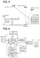
- Fig. 6 is a block diagram showing general features of a navigation system as known in the past.
- the navigation system shown in Fig. 6 comprises a GPS satellite 28, vehicle position calculating means 20 for calculating a position of a vehicle based on data from the GPS satellite 28, information retrieval means 23 for retrieving data such as a facility to be utilized, route searching means 21 for searching a route up to the facility, guiding means 22 for guiding the vehicle along the searched route, display control means 25 for displaying data on display means 26 such as liquid crystal display unit or CRT display, and a map data 27 stored in a storage medium such as CD-ROM.
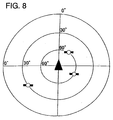
- Fig. 7 shows an example, in which three GPS satellites in the sky can be seen from the vehicle. If this is represented in the sky chart shown in Fig. 8, the GPS satellites are seen at three different bearings or azimuths with respect to the advancing direction of the vehicle, and correct position measurement can be achieved in this case. Specifically, using azimuth of the vehicle and azimuth of the road, a correct road is identified by map matching. If the GPS satellites are under this condition, it is possible to correctly identify the position of the vehicle and the road where the vehicle is running.
- a road which comprises two or more parallel roads and is constructed in multiple layers, there are an upper layer and a lower layer. Because the position of the vehicle projected on horizontal plane is the same, it is difficult to correctly identify on which of these layers the vehicle is located. As a result, when the user utilizes a highway map (a map for city expressway), audio guidance, or emergency information system, complete reliability is not always assured.
- a highway map a map for city expressway
- audio guidance, or emergency information system complete reliability is not always assured.
- a gyro which can detect pitching of the vehicle (whether it is ascending or descending in advancing direction). In this case, it is detected whether the vehicle has gone up on an ascending slope to enter a road on an elevated highway or has gone down on a descending slope to leave the elevated road, and it is judged whether the vehicle is running on a road (upper layer) constructed on the elevated highway, or it is running on a planar road (lower layer) under the elevated road.
- a road upper layer
- planar road lower layer
- a method for identifying a position of a vehicle on a multi-layer road to identify whether the vehicle running on one of the layers of the multi-layer road is running on the uppermost layer or on a lower layer under the uppermost layer of the multi-layer road, whereby, in case the ratio of a distance in a section where GPS position measurement can be achieved in a predetermined traveling distance is equal to or higher than a predetermined threshold for identification of the upper layer, it is judged that the vehicle is running on the upper layer (the uppermost layer), and if the ratio is lower than the other predetermined threshold for identification of lower layer, it is judged that the vehicle is running on the lower layer (a layer under the uppermost layer).
- the term "upper layer” means the uppermost layer as described above, and the term “lower layer” means a layer under the uppermost layer. That is, in case of 3-layer structure, the uppermost layer is the upper layer, and each of two layers under the uppermost layer is the lower layer.
- a method for identifying a position of a vehicle on a multi-layer road to identify whether the vehicle running on one of the layers of the multi-layer road is running on the uppermost layer or on a lower layer under the uppermost layer of the multi-layer road, whereby, in case the section where GPS position measurement can be achieved in the predetermined traveling distance is discrete, it is identified as the lower layer, and it is possible to identify the lower layer of the multi-layer road without using additional new devices and parts on the navigation system.
- a method for identifying a position of a vehicle on a multi-layer road to identify whether the vehicle running on one of the layers of the multi-layer road is running on the uppermost layer or on a lower layer under the uppermost layer of the multi-layer road, whereby, if satellites at left and right are equally seen with respect to the advancing direction of the vehicle, it is identified as the upper layer, and if not, it is judged as the lower layer.
- a method for identifying a position of a vehicle on a multi-layer road to identify whether the vehicle running on one of the layers of the multi-layer road is running on the uppermost layer or on a lower layer under the uppermost layer of the multi-layer road, whereby, if a satellite above a lane in opposite direction with respect to the advancing direction of the vehicle is seen, it is judged as the upper layer, and if not, it is judged as the lower layer.
- a method for identifying a position of a vehicle as described above can be provided, wherein if the level of receiving signal from a satellite above a lane in opposite direction with respect to the advancing direction of the vehicle is lower than the level of receiving signals from a satellite in reverse direction to the lane in opposite direction, it is judged the vehicle is running on an apparent upper layer and not on a true upper layer and there are provided effects that an apparent upper layer identified erroneously because of reflection from a building or the like is not identified as a true upper layer.
- Fig. 1 is a drawing to explain a method for identifying or detecting a position of a vehicle on a multi-layer road in an embodiment of the present invention.
- a vehicle A is shown as a vehicle running on a road constructed on an elevated highway.
- a vehicle B and a vehicle C are shown as vehicles running on a road under the elevated highway. It is assumed that a first building and a second building higher than the elevated road are constructed each on one side of the road.
- Each of the vehicles is provided with a navigation system, by which a position information can be calculated using GPS satellite.
- the sky can be seen in a part of the advancing direction as shown in Fig. 2C, but visual field of the driver is shielded in leftward and rightward directions by the first building and by support pillars of the elevated road.
- the area of each of the shaded portions showing the range where the satellite can be seen from the vehicle is narrowed down in the order of vehicle A ⁇ vehicle B ⁇ vehicle C.
- the expression "the satellite can be seen” means that electric field intensity of electric wave from the satellite received by the vehicle is equal to or higher than a predetermined value, and it does not mean that the satellite can be seen in optical sense of the words.
- the expression "the sky can be seen” means that, under the assumption that innumerable satellites are present in the sky, electric field intensity of electric wave received from these satellites by the vehicle is equal to or higher than a predetermined value.
- the sky can be partially seen in leftward and right directions in case the vehicle is at a position where there is no obstacle at left and right, e.g. when the vehicle is going to enter an intersection.
- Position measuring ratio (%) (Traveled distance where GPS position measuring is effective) ⁇ 100/(Traveled distance) .
- the position measuring ratio is 80%. If the position measuring ratio is higher than a threshold for identification of the upper, it is judged as the upper layer. If the position measuring ratio is not higher than a threshold for identification of the lower layer, it is judged as the lower layer.
- GPS position measurement can be achieved means that it is under the condition that at least three satellites can be seen to determine the position of the vehicle by GPS satellites. This is based on the same principle as trigonometrical survey. If the data are not available from more than three satellites, it is regarded as "GPS position measurement cannot be achieved".
- the ratio of a distance of the sections where GPS position measurement can be achieved in the traveled distance of a given section is more than the threshold for identification of the upper layer, it is judged as the upper layer. If it is lower than the threshold for identification of the lower layer, it is judged as the lower layer. In this case, for the lower layer, the position measuring ratio is exceptionally increased near an intersection, while the position measuring ratio is equally good for the upper layer, and the position of the vehicle on the multi-layer road can be identified.
- the threshold for identification can be determined as an arbitrary value, and it is not an absolute value.
- Fig. 3 is a flow chart showing operation of a first embodiment of the present invention based on the position measuring ratio.
- Step 31 referring to map data, it is identified whether the present position of the vehicle is on a multi-layer road section or not. Specifically, a signal to show whether it is on multi-layer road or not is included in the road map in advance, and it is identified from the relation with the position of the vehicle. If the answer is "No", the procedure is completed without identification procedure. If the answer is "Yes", it is advanced to Step 32, and the position measuring ratio is calculated. Then, in Step 33, the threshold for identification of upper or lower layer corresponding to the traveled distance is retrieved from the table.
- Step 34 it is identified whether the position measuring ratio is higher than the upper layer threshold or not. If the answer is “Yes”, it is judged as the upper layer. If the answer is "No”, it is advanced to Step 35, and it is judged whether the position measuring ratio is lower than the threshold for the lower layer or not. If the answer is “Yes”, it is judged as the lower layer. If the answer is "No”, it is judged that it cannot be identified whether it is the upper layer or the lower layer.
- Fig. 4 is a flow chart showing operation of a second embodiment of the present invention based on the position measuring ratio.
- Step 41 it is judged whether it is a multi-layer road section or not as in Fig. 3 described above. If the answer is "No", the procedure is completed without identifying. If the answer is "Yes”, it is advanced to Step 42, and the position measuring ratio is calculated for each section of 100 m.
- Step 43 it is judged whether the data has been accumulated for a distance of 800 m.
- the distance 100 m or 800 m is not an absolute value, and it is an adequate road section determined from the circumstances on the road. If the condition for the Step 43 is not satisfied, i.e.
- Step 45 it is judged whether the difference is higher than the threshold or not. If the answer is "No", judgment is not made. If the answer is "Yes”, it can be identified as the lower layer. Specifically, in a vehicle running on the lower layer, the position measuring ratio is generally low because the elevated road is present above the vehicle. In an intersection, however, the position measuring ratio increases because visual field of the driver is open in lateral direction. As a result, the difference between maximum value and minimum value of the position measuring ratio is higher than the predetermined value. Based on this principle, it is judged as the lower layer in case the difference between maximum value and minimum value of the position measuring ratio is higher than the predetermined threshold.
- the range where electric wave from GPS satellite can be received is narrowed down on the sky chart in case of the lower layer road as shown in Figs. 2A to 2C.
- average number of GPS satellites, from which electric wave can be received is decreased, and the probability not to accomplish position measurement is increased.
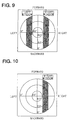
- the vehicle when the vehicle is driven on the multi-layer road and if satellites can be seen above the lane in opposite direction with respect to the advancing direction of the vehicle as shown in the sky charts shown in Fig. 2A, Fig. 2B or Fig. 2C, it can be identified as the upper layer. If not, it can be identified as the lower layer. That is, in case the vehicle is running on left side on the road, and if satellite is seen on right window as shown in Fig. 10, it is judged as the upper layer. If not, it is judged as the lower layer.
- Fig. 5 there may be an apparent (i.e. untrue) condition where three satellites can be seen because of the reflection from an object such as a building. More concretely, a satellite X and a satellite Y can be directly seen as shown in the figure, and there is no problem in position measurement. But, the signal from a satellite Z is reflected by a building. As a result, there is an apparent condition that three GPS satellites can be seen. However, intensity of the signal from the satellite Z reflected by the building is weaker than the intensity of the other satellite X or Y, and this situation can be easily discriminated from each other.
- an information necessary for calculation of vehicle position using GPS satellite is a position measuring information, and this information is utilized by almost all types of navigation systems as an information of whether position measurement is effective or ineffective. Because the method according to the present invention utilizes this information, superb effects can be provided without using additional new devices or parts in almost all types of navigation systems.
Landscapes
- Engineering & Computer Science (AREA)
- Radar, Positioning & Navigation (AREA)
- Remote Sensing (AREA)
- Physics & Mathematics (AREA)
- General Physics & Mathematics (AREA)
- Automation & Control Theory (AREA)
- Navigation (AREA)
- Traffic Control Systems (AREA)
- Position Fixing By Use Of Radio Waves (AREA)
Abstract
Description
Claims (5)
- A method for identifying a position of a vehicle on a multi-layer road for judging whether a vehicle running on one of the layers of the multi-layer road is running on the uppermost layer or on a lower layer under the uppermost layer of the multi-layer road, whereby, in case a ratio of a distance of a road section where GPS position measuring can be achieved in a predetermined traveling distance is equal to or higher than a predetermined threshold for identification of an upper layer, it is judged that the vehicle is running on the upper layer of the multi-layer road, and in case said ratio is lower than the other predetermined threshold for identification of a lower layer, it is judged that the vehicle is running on the lower layer of the multi-layer road.
- A method for identifying a position of a vehicle on a multi-layer road for judging whether a vehicle running on one of the layers of the multi-layer road is running on the uppermost layer or on a lower layer under the uppermost layer of the multi-layer road, whereby, in case a section where GPS position measurement can be achieved in a predetermined traveling distance is discrete, it is judged as the lower layer.
- A method for identifying a position of a vehicle on a multi-layer road for judging whether a vehicle running on one of the layers of the multi-layer road is running on the uppermost layer or on a lower layer under the uppermost layer of the multi-layer road, whereby, if satellites at left and right are equally seen with respect to the advancing direction of the vehicle, it is judged that the vehicle is running on the upper layer of the multi-layer road, and if the satellites are not seen equally, it is judged that the vehicle is running on the lower layer of the multi-layer road.
- A method for identifying a position of a vehicle on a multi-layer road for judging whether a vehicle running on one of the layers of the multi-layer road is running on the uppermost layer or on a lower layer under the uppermost layer of the multi-layer road, whereby, if a satellite above a lane in opposite direction with respect to the advancing direction of the vehicle is seen, it is judged that the vehicle is running on the upper layer, and if not, it is judged that the vehicle is running on the lower layer.
- The method for identifying a position of a vehicle on a multi-layer road according to claim 4, wherein if the level of receiving signal from a satellite above a lane in opposite direction with respect to the advancing direction of the vehicle is lower than the level of receiving signals from a satellite in reverse direction to the lane in opposite direction, it is judged the vehicle is running on an apparent upper layer and not on a true upper layer.
Applications Claiming Priority (3)
| Application Number | Priority Date | Filing Date | Title |
|---|---|---|---|
| JP681199 | 1999-01-13 | ||
| JP11006811A JP3027574B1 (en) | 1999-01-13 | 1999-01-13 | Vehicle road position discrimination method on multi-layer roads |
| PCT/JP2000/000131 WO2000042386A1 (en) | 1999-01-13 | 2000-01-13 | Method for detecting road position of car in multiformation road |
Publications (2)
| Publication Number | Publication Date |
|---|---|
| EP1063492A1 true EP1063492A1 (en) | 2000-12-27 |
| EP1063492A4 EP1063492A4 (en) | 2010-03-24 |
Family
ID=11648594
Family Applications (1)
| Application Number | Title | Priority Date | Filing Date |
|---|---|---|---|
| EP00900371A Withdrawn EP1063492A4 (en) | 1999-01-13 | 2000-01-13 | METHOD FOR DETECTING THE POSITION OF A CAR ON A ROAD WITH SEVERAL SUPERIMPOSED WAYS |
Country Status (5)
| Country | Link |
|---|---|
| US (1) | US6385540B1 (en) |
| EP (1) | EP1063492A4 (en) |
| JP (1) | JP3027574B1 (en) |
| SG (3) | SG102038A1 (en) |
| WO (1) | WO2000042386A1 (en) |
Cited By (5)
| Publication number | Priority date | Publication date | Assignee | Title |
|---|---|---|---|---|
| EP1150100B1 (en) * | 2000-04-28 | 2007-06-06 | Pioneer Corporation | Navigation apparatus and information recording medium containing navigation program readable by computer |
| FR3034205A1 (en) * | 2015-03-24 | 2016-09-30 | Peugeot Citroen Automobiles Sa | METHOD FOR MONITORING THE BEHAVIOR OF A VEHICLE CIRCULATING ON A MULTIVOY ROAD NETWORK |
| FR3034206A1 (en) * | 2015-03-24 | 2016-09-30 | Peugeot Citroen Automobiles Sa | METHOD FOR MONITORING THE BEHAVIOR OF A VEHICLE CIRCULATING ON A ROAD NETWORK |
| CN109959894A (en) * | 2017-12-26 | 2019-07-02 | 深圳市优必选科技有限公司 | Positioning method and terminal equipment |
| CN113419266A (en) * | 2021-08-23 | 2021-09-21 | 腾讯科技(深圳)有限公司 | Positioning method and device, electronic equipment and computer readable storage medium |
Families Citing this family (16)
| Publication number | Priority date | Publication date | Assignee | Title |
|---|---|---|---|---|
| US6604048B2 (en) * | 2000-08-09 | 2003-08-05 | Aisin Aw Co., Ltd. | Car navigation system and storage medium |
| JP2002174528A (en) * | 2000-09-29 | 2002-06-21 | Clarion Co Ltd | Car navigation system and method, software for car navigation and recording medium having recorded car navigation software |
| KR100448389B1 (en) * | 2002-08-23 | 2004-09-10 | 현대자동차주식회사 | Method and apparatus for determining vehicle location on a map |
| JP4258225B2 (en) * | 2003-02-14 | 2009-04-30 | トヨタ自動車株式会社 | Vehicle position detection apparatus and method |
| JP4467366B2 (en) * | 2004-06-21 | 2010-05-26 | アルパイン株式会社 | Navigation device and building facility approach determination method |
| KR101154079B1 (en) | 2005-02-16 | 2012-06-11 | 삼성전자주식회사 | Method for determining initial location of navigation apparatus |
| KR101609679B1 (en) * | 2009-03-31 | 2016-04-06 | 팅크웨어(주) | Apparatus for map matching of navigation using planar data of road and method thereof |
| US9189976B2 (en) | 2013-07-10 | 2015-11-17 | Telenav Inc. | Navigation system with multi-layer road capability mechanism and method of operation thereof |
| JP6169945B2 (en) * | 2013-10-25 | 2017-07-26 | アルパイン株式会社 | Navigation device and elevated vertical path determination method |
| JP6332010B2 (en) * | 2014-12-18 | 2018-05-30 | 株式会社デンソー | In-vehicle machine |
| CN105547309B (en) * | 2015-12-02 | 2018-11-02 | 百度在线网络技术(北京)有限公司 | A kind of recognition methods of overpass road and device |
| US20180335306A1 (en) * | 2017-05-16 | 2018-11-22 | GM Global Technology Operations LLC | Method and apparatus for detecting road layer position |
| US10922969B2 (en) * | 2018-06-04 | 2021-02-16 | GM Global Technology Operations LLC | Systems, methods and apparatuses for detecting elevated freeways to prevent engaging cruise features |
| CN113049029A (en) * | 2021-03-06 | 2021-06-29 | 义乌市叶微建筑科技有限公司 | Urban road operation safety online monitoring cloud platform based on wireless communication technology |
| CN116069794B (en) * | 2022-12-30 | 2025-10-24 | 广州小鹏自动驾驶科技有限公司 | Map information updating method, device, equipment and computer-readable storage medium |
| CN118571026B (en) * | 2024-05-17 | 2025-04-11 | 福建省高速公路科技创新研究院有限公司 | Method and system for accurate vehicle identification on upper and lower composite highways |
Family Cites Families (10)
| Publication number | Priority date | Publication date | Assignee | Title |
|---|---|---|---|---|
| JP2745588B2 (en) * | 1988-11-18 | 1998-04-28 | 日産自動車株式会社 | Elevated expressway driving recognition device |
| JPH06148307A (en) * | 1992-11-04 | 1994-05-27 | Pioneer Electron Corp | Navigation device |
| JP3120924B2 (en) * | 1993-05-21 | 2000-12-25 | 三菱電機株式会社 | Car navigation system |
| JP3851376B2 (en) * | 1996-05-15 | 2006-11-29 | 日本無線株式会社 | Positioning system satellite signal receiver |
| US6160841A (en) * | 1996-05-24 | 2000-12-12 | Leica Geosystems Inc. | Mitigation of multipath effects in global positioning system receivers |
| JP3375258B2 (en) * | 1996-11-07 | 2003-02-10 | 株式会社日立製作所 | Map display method and device, and navigation device provided with the device |
| JP3540106B2 (en) * | 1996-11-11 | 2004-07-07 | 三菱電機株式会社 | Navigation apparatus for mobile object, current position determination method thereof, and medium storing current position determination program |
| EP0863381B1 (en) * | 1997-03-07 | 2004-06-02 | Pioneer Electronic Corporation | Navigation apparatus |
| JP3582560B2 (en) * | 1997-07-08 | 2004-10-27 | アイシン・エィ・ダブリュ株式会社 | Vehicle navigation device and recording medium |
| JP2963994B1 (en) * | 1998-09-02 | 1999-10-18 | 郵政省通信総合研究所長 | Method of creating sky view range by location |
-
1999
- 1999-01-13 JP JP11006811A patent/JP3027574B1/en not_active Expired - Fee Related
-
2000
- 2000-01-13 SG SG200200949A patent/SG102038A1/en unknown
- 2000-01-13 US US09/623,794 patent/US6385540B1/en not_active Expired - Lifetime
- 2000-01-13 WO PCT/JP2000/000131 patent/WO2000042386A1/en not_active Ceased
- 2000-01-13 SG SG200201098A patent/SG104299A1/en unknown
- 2000-01-13 SG SG200201099A patent/SG105538A1/en unknown
- 2000-01-13 EP EP00900371A patent/EP1063492A4/en not_active Withdrawn
Cited By (6)
| Publication number | Priority date | Publication date | Assignee | Title |
|---|---|---|---|---|
| EP1150100B1 (en) * | 2000-04-28 | 2007-06-06 | Pioneer Corporation | Navigation apparatus and information recording medium containing navigation program readable by computer |
| FR3034205A1 (en) * | 2015-03-24 | 2016-09-30 | Peugeot Citroen Automobiles Sa | METHOD FOR MONITORING THE BEHAVIOR OF A VEHICLE CIRCULATING ON A MULTIVOY ROAD NETWORK |
| FR3034206A1 (en) * | 2015-03-24 | 2016-09-30 | Peugeot Citroen Automobiles Sa | METHOD FOR MONITORING THE BEHAVIOR OF A VEHICLE CIRCULATING ON A ROAD NETWORK |
| CN109959894A (en) * | 2017-12-26 | 2019-07-02 | 深圳市优必选科技有限公司 | Positioning method and terminal equipment |
| CN113419266A (en) * | 2021-08-23 | 2021-09-21 | 腾讯科技(深圳)有限公司 | Positioning method and device, electronic equipment and computer readable storage medium |
| CN113419266B (en) * | 2021-08-23 | 2021-12-10 | 腾讯科技(深圳)有限公司 | Positioning method and device, electronic equipment and computer readable storage medium |
Also Published As
| Publication number | Publication date |
|---|---|
| SG105538A1 (en) | 2004-08-27 |
| SG102038A1 (en) | 2004-02-27 |
| US6385540B1 (en) | 2002-05-07 |
| EP1063492A4 (en) | 2010-03-24 |
| JP2000205867A (en) | 2000-07-28 |
| WO2000042386A1 (en) | 2000-07-20 |
| SG104299A1 (en) | 2004-06-21 |
| JP3027574B1 (en) | 2000-04-04 |
Similar Documents
| Publication | Publication Date | Title |
|---|---|---|
| US6385540B1 (en) | Method for detecting road position of car in multiformation road | |
| US5337245A (en) | Location detecting apparatus with overspeed predicting means | |
| US6498983B2 (en) | Navigation apparatus, navigation method and information recording medium containing navigation program readable by computer | |
| EP1076276B1 (en) | Automatic travel guiding device for vehicle | |
| US8134480B2 (en) | Image processing system and method | |
| US5459667A (en) | Navigation apparatus for informing vehicle driver of information regarding travel route | |
| EP2491344B1 (en) | System and method for vehicle navigation using lateral offsets | |
| EP0836074B1 (en) | Route guidance system and method for use in vehicle navigation | |
| EP1995557B1 (en) | Position registration device, route search device, position registration method, position registration program, and recording medium | |
| US20050187705A1 (en) | Apparatus for predicting road shape | |
| US20080243378A1 (en) | System and method for vehicle navigation and piloting including absolute and relative coordinates | |
| US20030023369A1 (en) | Vehicle-mounted position computing apparatus | |
| JP2008026032A (en) | Vehicle navigation device | |
| JP2007178182A (en) | Own vehicle position determination device | |
| US6604048B2 (en) | Car navigation system and storage medium | |
| JP2544855B2 (en) | Vehicle guidance device | |
| US4982359A (en) | System and method for recognizing vehicle position on elevated freeway | |
| KR19990058332A (en) | Guide to Deviation of the Path of Vehicle Navigation System | |
| JPH10100821A (en) | Forward vehicle recognition device | |
| JP2001272236A (en) | Vehicle information processing device | |
| JP2000205871A (en) | Vehicle road position discrimination method on multi-layer roads | |
| KR100342225B1 (en) | Elevated road recognition vehicle navigation device and control method thereof | |
| KR19990058323A (en) | Intersection guidance method of vehicle navigation system | |
| KR19990058333A (en) | Reverse Driving Guide for Vehicle Navigation System | |
| KR19990002405A (en) | Map matching method using 3 axis angular sensor and car navigation system using the same |
Legal Events
| Date | Code | Title | Description |
|---|---|---|---|
| PUAI | Public reference made under article 153(3) epc to a published international application that has entered the european phase |
Free format text: ORIGINAL CODE: 0009012 |
|
| AK | Designated contracting states |
Kind code of ref document: A1 Designated state(s): AT BE CH CY DE DK ES FI FR GB GR IE IT LI LU MC NL PT SE |
|
| 17P | Request for examination filed |
Effective date: 20010117 |
|
| RAP1 | Party data changed (applicant data changed or rights of an application transferred) |
Owner name: PANASONIC CORPORATION |
|
| A4 | Supplementary search report drawn up and despatched |
Effective date: 20100219 |
|
| RIC1 | Information provided on ipc code assigned before grant |
Ipc: G01C 21/26 20060101AFI20000727BHEP Ipc: G08G 1/0969 20060101ALI20100215BHEP Ipc: G01S 5/14 20060101ALI20100215BHEP |
|
| 17Q | First examination report despatched |
Effective date: 20100715 |
|
| STAA | Information on the status of an ep patent application or granted ep patent |
Free format text: STATUS: THE APPLICATION IS DEEMED TO BE WITHDRAWN |
|
| 18D | Application deemed to be withdrawn |
Effective date: 20101126 |