EP1063430B1 - Centrifugal compressor and shaft seal - Google Patents
Centrifugal compressor and shaft seal Download PDFInfo
- Publication number
- EP1063430B1 EP1063430B1 EP98907220A EP98907220A EP1063430B1 EP 1063430 B1 EP1063430 B1 EP 1063430B1 EP 98907220 A EP98907220 A EP 98907220A EP 98907220 A EP98907220 A EP 98907220A EP 1063430 B1 EP1063430 B1 EP 1063430B1
- Authority
- EP
- European Patent Office
- Prior art keywords
- oil
- rotary shaft
- seal
- seal ring
- centrifugal compressor
- Prior art date
- Legal status (The legal status is an assumption and is not a legal conclusion. Google has not performed a legal analysis and makes no representation as to the accuracy of the status listed.)
- Expired - Lifetime
Links
- 238000007789 sealing Methods 0.000 claims description 19
- 238000007872 degassing Methods 0.000 claims description 7
- 238000001816 cooling Methods 0.000 claims description 3
- 239000007789 gas Substances 0.000 description 55
- 210000003128 head Anatomy 0.000 description 13
- 239000007788 liquid Substances 0.000 description 4
- 238000005461 lubrication Methods 0.000 description 4
- 239000000203 mixture Substances 0.000 description 3
- 230000002093 peripheral effect Effects 0.000 description 3
- 239000000126 substance Substances 0.000 description 2
- 238000005299 abrasion Methods 0.000 description 1
- 230000004323 axial length Effects 0.000 description 1
- 230000001627 detrimental effect Effects 0.000 description 1
- 210000003027 ear inner Anatomy 0.000 description 1
- 230000000694 effects Effects 0.000 description 1
- 230000008030 elimination Effects 0.000 description 1
- 238000003379 elimination reaction Methods 0.000 description 1
- 239000012535 impurity Substances 0.000 description 1
- 230000007774 longterm Effects 0.000 description 1
- 238000000034 method Methods 0.000 description 1
- 238000005504 petroleum refining Methods 0.000 description 1
- 239000011295 pitch Substances 0.000 description 1
- 230000005855 radiation Effects 0.000 description 1
- 239000002341 toxic gas Substances 0.000 description 1
Images

Classifications
-
- F—MECHANICAL ENGINEERING; LIGHTING; HEATING; WEAPONS; BLASTING
- F04—POSITIVE - DISPLACEMENT MACHINES FOR LIQUIDS; PUMPS FOR LIQUIDS OR ELASTIC FLUIDS
- F04D—NON-POSITIVE-DISPLACEMENT PUMPS
- F04D29/00—Details, component parts, or accessories
- F04D29/08—Sealings
- F04D29/10—Shaft sealings
- F04D29/12—Shaft sealings using sealing-rings
- F04D29/122—Shaft sealings using sealing-rings especially adapted for elastic fluid pumps
- F04D29/124—Shaft sealings using sealing-rings especially adapted for elastic fluid pumps with special means for adducting cooling or sealing fluid
-
- F—MECHANICAL ENGINEERING; LIGHTING; HEATING; WEAPONS; BLASTING
- F04—POSITIVE - DISPLACEMENT MACHINES FOR LIQUIDS; PUMPS FOR LIQUIDS OR ELASTIC FLUIDS
- F04D—NON-POSITIVE-DISPLACEMENT PUMPS
- F04D17/00—Radial-flow pumps, e.g. centrifugal pumps; Helico-centrifugal pumps
- F04D17/08—Centrifugal pumps
- F04D17/10—Centrifugal pumps for compressing or evacuating
- F04D17/12—Multi-stage pumps
- F04D17/122—Multi-stage pumps the individual rotor discs being, one for each stage, on a common shaft and axially spaced, e.g. conventional centrifugal multi- stage compressors
Definitions
- the present invention relates to a centrifugal compressor according to preamble of claim 1.
- This oil film seal has following features:
- the oil film seal forms an oil film having a pressure which is slightly higher than a pressure of the working gas in the compressor, between the sealing ring and the shaft, so as to seal the gas.
- a single oil film seal system has two seal rings one of which is located on the inside side (gas side) of a centrifugal compressor and the other one of which is located on the outside (atmospheric side) of the compressor. These seal rings are incorporated in a seal housing formed in a casing so as to define extremely narrow clearances between themselves and a rotary shaft and to follow fine motion of the rotary shaft. Oil having a pressure which is slightly higher than the gas in the compressor is fed into a space between two seal rings, one of which is on the inside of the compressor and the other is on the outside of the compressor.
- the seal ring is fitted on the rotary shaft with a clearance defined therebetween, and the so-called sealing sleeve is normally shrinkage-fitted on the rotary shaft in a part facing the outer seal ring in order to protect the rotary shaft surface. Since seal oil is fed at the outer peripheral side in the oil film seal, this seal ring is heated by the seal oil so as to expand, and accordingly, unbalance load would possibly be applied to the rotary shaft. As a result, there would have been such a disadvantage that the rotor including the rotary shaft incurs unbalance vibration. Japanese Laid-Open No.
- S58-85395 discloses a shaft seal system capable of eliminating clogging of a seal part, comprising a pressure equalizing chamber connected to a top part of a head tank, a seal oil supply chamber connected to the bottom part of the head tank and an atmospheric chamber communicated with the atmosphere, which are arranged in order in the axial direction, and seal rings arranged in the seal oil supply chamber with a clearance defined between themselves and a shaft.
- a valve located on the clogging side is closed in order to open the pressure equalizing chamber to the atmosphere.
- the shaft seal oil supply chamber is applied with a pressure which is a sum of the pressure in the pressure equalizing chamber on the side on which the valve is opened, and the pressure corresponding to the head of the oil in the head tank.
- a pressure which is a sum of the pressure in the pressure equalizing chamber on the side on which the valve is opened, and the pressure corresponding to the head of the oil in the head tank.
- the present invention is devised in view of the above-mentioned problems and disadvantages inherent to the prior art, and one object of the present invention is to provide an oil film seal used in a centrifugal compressor with an enhanced reliability. Further, in particular, an object of the present invention is to provide an oil film seal system which can prevent a gas side seal ring from being damaged by burning and consequently enhance the reliability, correspondingly to provide a centrifugal compressor incorporating an oil film seal system which can reduce unbalance vibration of a rotor caused by unbalance of a seal part with only a simple structure.
- a centrifugal compressor comprising a rotary shaft, a casing attached thereto with bearing means for rotatably journalling the rotary shaft, at least one centrifugal impeller fitted to the rotary shaft, a shaft seal system for preventing gas compressed by the centrifugal impeller from leaking through a gap between said rotary shaft and the casing, the shaft seal system comprising a gas side seal ring arranged axially outside of the impeller with a radial clearance between itself and the casing, and an atmospheric side seal ring located outside from the gas side seal ring with a radial clearance between the casing, and an oil feed passage for supplying oil to both seal rings is formed in the rotary shaft, the above-mentioned oil feed passage having an opening at a position corresponding to the above-mentioned gas side seal ring.
- the bearing means are provided at two positions in the axial direction, and two shaft seal systems are provided inward from the bearing means in the axial direction of the compressor, or alternatively, the oil passage formed in the rotary shaft has an opening at one end of the rotary shaft, an oil feed bore passing through the center axial part of the rotary shaft, a plurality of oil feed holes communicated with the oil feed bore and formed in the rotary shaft so as to be extended radially outward, the plurality of feed holes being located at an axial position which is in an axially intermediate part of the gas side seal ring, the rotary shaft is incorporated thereon with sealing sleeves for covering the rotary shaft, corresponding to positions where the gas side seal ring and the atmospheric side seal ring are provided respectively, the rotary shaft is provided with a chamber for reserving oil fed from the oil feed bore, at the one end side where the oil feed bore is opened, these sealing sleeves having a hole radially piercing therethrough at positions corresponding to the opening of the oil feed passage, a chamber for
- a centrifugal compressor having oil film seal systems provided at two positions in the axial direction of the rotary shaft, a first bore is formed in the center axial part of the rotary shaft, and second holes are formed in the rotary shaft at positions where the oil seal systems are attached, being communicated with the first bore and opened at the outer periphery of the rotary shaft.
- the oil film seal system has a gas side seal ring and an atmospheric side seal ring, a degassing means for cooling the gas side seal ring so as to remove working gas components from oil mixed therewith, and a reservoir for mixing oil with which the atmospheric side seal ring has been cooled, and the oil from which the working gas is removed by the degassing means, with each other.
- an shaft seal system for a centrifugal compressor comprising a gas side seal ring and an atmospheric side seal ring which are loosely fitted in a housing, and sealing sleeves located on the inner diameter sides of these seal rings, and each having a plurality of holes radially extending through the sleeves, the plurality of holes in the sealing sleeves including those formed at positions corresponding to at least the gas side seal ring.
- a head tank for reserving oil adapted to be fed to both seal rings through the plurality of holes at the inner diameter side, and a control means for controlling the level of the oil in the head tank.
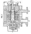
- Fig. 1 is a longitudinal sectional view illustrating a multi-stage centrifugal compressor according to the present invention
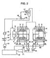
- Fig. 2 is a view which shows a first embodiment of the present invention, and in which an oil feed system and an oil film seal part in the multistage centrifugal compressor is shown in detail in a section.
- working gas sucked through a suction port 31 is compressed as the rotary shaft 1 is rotated, so as to have a desired pressure before it is fed into a source of demand.
- This single-shaft multistage compressor 100 is a high large capacity, and further, requires seal means for prevent the working gas from leaking from the compressor 100 since the working gas discharged from a discharge port 32 is high.
- the high pressure seal means an oil film seal as discussed mentioned above, is preferable, and accordingly, in general, oil film seal systems are provided inside of the shaft seal systems 50, 52.
- the oil film seal systems 60, 62 are connected with each other by a balance pipe line which is not shown, so as to set the pressure of the atmospheric gas of both oil film seal systems 60, 62 to a value which is substantially equal to the suction pressure of the working gas. It is noted that one and the same kind of oil is fed to the bearing devices 50, 52 and the shaft seal systems 60, 62.
- Fig. 2 shows, in detail, a part A of the single-shaft multistage compressor illustrated in Fig. 1, in which an oil feed system and the seal systems 60, 62 are provided.
- Seal oil 8 adapted to be fed into the seal systems 60, 62 is reserved in an oil reservoir 12 which is separately provided to the body of the single-shaft multistage compressor 100.
- the seal oil 8 reserved in the oil reservoir 12 is pressurized by an oil pump 13, and thereafter, is cooled by an oil cooler 14. Then, the seal oil 8 is passed through an oil filter 15 for removing foreign matter in order to be circulated being used as fresh lubrication oil and seal oil.
- the oil from which impurities are removed, and is adjusted to a pressure required for the oil film seal systems 60, 62 before it is fed into a chamber 7 provided in an end part of the rotary shaft 1 on the suction side.
- a height of the liquid surface of the oil in a head tank 18 is detected by a level gage from which delivers a detected value to a controller 17 in order to adjust the pressure of the oil.
- the controller 17 adjusts the opening degree of a control valve 16 in order to maintain the height of the liquid surface of the oil in the head tank 18 at a constant value.
- the height of the liquid surface of the oil is adjusted so as to set the pressure differential between the pressure of the seal oil and the suction pressure of the working gas to about a 0.5 kg/cm 2 .
- a check valve 19 which is provided between the control valve 16 and the head tank 18, can prevent the seal oil 8 reserved in the head tank 18 from counter-flowing toward the reservoir 12 so as to cause a shortage of oil in the oil film seal systems 60, 62.
- the seal oil 8 fed into the chamber 7 provided at the one end part of the rotary shaft 1, is led through an oil feed bore 4 deeply formed in the center axial part of the rotary shaft 1 so as to extend in the axial direction of the rotary shaft 1 up to the discharge side seal system 60, and oil feed holes 5 communicated with the oil feed bore 4 and radially formed in the rotary shaft 1, and is then fed into the gas side seal ring 2 by way of holes formed in a sealing sleeves 20 shrinkage-fitted on the rotary shaft 1.
- a mechanical seal 6 is provided on the rotary shaft 1 in the vicinity of an axial one end thereof in order to prevent the seal oil from leaking from the compressor in the vicinity of the oil feed bore 4.
- the remainder of the seal oil 8 fed into the oil film seal systems 60, 62 absorbs heat from the gas side seal ring 2 and those therearound so as to raise its temperature up to a high value. Then, it flows through the clearance between the atmospheric side seal ring 3 and the shaft 1, and flows into an oil discharge hole 23 formed in an axial end of the shaft before it returns into an oil reservoir 12.
- the discharged oil which is a mixture of working gas once reserved in a drain port 10, and the seal oil 8, is led into a degassing tank 11.
- Working gas components are removed from the mixture of the working gas and the seal oil 8 in the degassing tank 11, and accordingly, only the seal oil 8 is returned into the oil reservoir 12 and is then reused or exhausted.
- the working gas removed from the mixture in the degassing tank 11 is properly treated if it is detrimental or burnable in order to prevent occurrence of pollution problems and accidents.
- the seal oil 8 is fed through the oil feed bore 4 and the holes 5 which are formed in the shaft, and accordingly, the oil 8 can be fed into the center part of the gas side seal ring 2. Accordingly, the axial length of the gas side seal ring 2 can be longer than that of the conventional one. Further, since the gas side seal ring 2 can be uniformly cooled substantially in its entirety, and accordingly, the effect of heat radiation can become higher. Moreover, since the temperature gradient of the seal ring part can be reduced, the clearance between the seal ring 2 and the rotary shaft 1 can be maintained at a substantially appropriate value. Accordingly, with the arrangement of this embodiment, it is possible to prevent occurrence of a problem of damage of the atmospheric seal ring by burning, which has often occurred conventionally.
- the rotary shaft 1 and the sealing sleeve 20 can be cooled down to one and the same temperature, substantially.
- the seal oil has been fed from the outer periphery of the rotary shaft, and as a result, the seal sleeve 20 having a thickness of about 3 mm, is heated up to a high temperature so as to thermally expand at first by the temperature of the working gas and frictional heat, but the rotary shaft having a diameter of about 100 mm does not greatly raise its temperature.
- the shrinkage fitting therebetween would possibly loosened, and accordingly, the sealing sleeve moves freely so as to cause unbalance vibration of the rotary shaft.
- the present invention having the above-mentioned arrangement, it is possible to radically prevent occurrence of this unbalance vibration.
- FIG. 3 Another embodiment of the present invention is shown in Fig. 3.
- Fig. 3 the oil feed from the outer periphery of the rotary shaft, which has been conventionally used, and the oil feed explained in the above-mentioned embodiment are used together.
- the oil film seal systems in this embodiment oil seal feed passages for feeding the seal oil 8 pressurized by the oil pump 13 to the seal rings 2, 3 are additionally formed.
- the sealing and the cooling can be surely made in comparison with the above-mentioned embodiment.
- the seal oil is fed from the inside of the rotary shaft, similar to the above-mentioned embodiment shown in Fig. 2, it is possible to prevent occurrence of vibration of the rotor caused by thermal expansion only of the gas side seal ring 2 and the sealing sleeve 20.
- Fig. 4 shows the rotary shaft 1 used in the above-mentioned two embodiments, in detail.
- the oil feed bore 4 is formed along the center axis of the axial center part of the rotary shaft 1.
- the radial oil feed holes 5 are formed in the rotary shaft 1 at a plurality of axial positions corresponding to the seal rings. As shown in a sectional view along line B-B in Fig. 4, these oil feed holes 5 are radially formed in the rotary shaft 1 so as to extend in the radial direction of the shaft from the center axis thereof, being angularly spaced at equal pitches. It is noted that the seal oil 8 fed through these radial holes 5 cools both the rotary shaft 1 and the sealing sleeves 20, simultaneously, and accordingly, the temperatures of the rotary shaft and the sealing rings 20 can be substantially maintained at one and the same value, as mentioned above.
- the seal ring can be prevented from being damaged by burning, due to the provision of the oil film seal, and the rotor can be prevented from being vibrated by being caused by thermal expansion of the sealing sleeves.
- the oil film seals are provided in the single-shaft multistage centrifugal compressor in the above-mentioned embodiment, the present invention may be applied in another type of compressors such as a single stage compressor or a multi-shaft type compressor.
Landscapes
- Engineering & Computer Science (AREA)
- Mechanical Engineering (AREA)
- General Engineering & Computer Science (AREA)
- Structures Of Non-Positive Displacement Pumps (AREA)
- Sealing Using Fluids, Sealing Without Contact, And Removal Of Oil (AREA)
Description
- The present invention relates to a centrifugal compressor according to preamble of
claim 1. - Heretofore, there has been widely used so-called oil film seals each having a seal ring fitted on a rotary shaft with a clearance therebetween, and oil is fed to the outer peripheral surface of the sealing ring through an oil feed passage formed in the casing side in order to seal working gas and bearing lubrication oil in a centrifugal compressor. For example, Japanese Laid-Open Patent No. H8-12109 discloses a device using an oil film seal, as mentioned above.
- This oil film seal has following features:
- (a) an oil film formed in the oil film seal system can completely seal working gas in a centrifugal compressor so as to prevent it from leaking from the compressor.
- (b) This oil film seal is noncontact type seal so that no slide parts including a mechanical seal or a lip seal are incorporated, and accordingly, friction and abrasion are less so that the long term continuous operation can be made. Further, due to the noncontact type, it can be used even though the peripheral speed of the rotary shaft of a seal part is high (about 80 m/s), and accordingly, it can be used in a high power machine.
- (c) By changing the pressure of oil to be fed, the working gas in the compressor can be sealed so as to be prevented from leaking into the outside of the compressor even though the pressure of the gas is high.
- (d) The oil film seal can remove heat generated in the seal part through the seal oil, and accordingly, the seal has highly safe and reliable.
- The oil film seal forms an oil film having a pressure which is slightly higher than a pressure of the working gas in the compressor, between the sealing ring and the shaft, so as to seal the gas. Further, a single oil film seal system has two seal rings one of which is located on the inside side (gas side) of a centrifugal compressor and the other one of which is located on the outside (atmospheric side) of the compressor. These seal rings are incorporated in a seal housing formed in a casing so as to define extremely narrow clearances between themselves and a rotary shaft and to follow fine motion of the rotary shaft. Oil having a pressure which is slightly higher than the gas in the compressor is fed into a space between two seal rings, one of which is on the inside of the compressor and the other is on the outside of the compressor. Some of the fed oil flows toward the atmospheric side seal ring while the remainder thereof flows into the compressor side through the annular clearance between the seal ring on the inside of the compressor and the shaft by a slight amount. Thus, it is possible to prevent the working gas in the compressor from flowing into the atmospheric side.
- In this conventional oil film seal system, oil discharged from the gas side is made into contact with gas in the compressor. Accordingly, the seal oil is excessively contaminated by the gas in the compressor if the gas is of a certain kind. Discharged oil which is possibly contaminated by a large degree, is led into a drain trap where the gas is separated from the oil, and then, the oil is retrieved or exhausted. In order to minimize the quantity of the exhausted oil which is so-called "sour drain", the following methods have been conventionally used:
- 1) The differential pressure between the supplied oil and the gas inside of compressor to be fed is lowered; and
- 2) The clearance between the gas side seal ring and the rotary shaft is reduced.
- If the differential pressure in the compressor is extremely small as stated in
item 1, the gas is likely to leak into the outside from the compressor, and meanwhile, if the clearance is extremely small as stated initem 2, the temperature at the inner surface of the gas side seal ring is raised excessively, resulting in that the seal ring is damaged by burning, or the possibility of a risk of making the seal ring into contact with the rotary shaft is increased. Indeed, there have been reported many accidents such that the gas side seal ring is damaged by burning. In particular, should any trouble occur in a centrifugal compressor as one of important components of any of various plants including a petroleum refining plant and a chemical plant, such a plant would be inoperative throughout the system. Thus, it is very important to ensure the reliability for the shaft seal system including the oil film seal system. - Further, the seal ring is fitted on the rotary shaft with a clearance defined therebetween, and the so-called sealing sleeve is normally shrinkage-fitted on the rotary shaft in a part facing the outer seal ring in order to protect the rotary shaft surface. Since seal oil is fed at the outer peripheral side in the oil film seal, this seal ring is heated by the seal oil so as to expand, and accordingly, unbalance load would possibly be applied to the rotary shaft. As a result, there would have been such a disadvantage that the rotor including the rotary shaft incurs unbalance vibration. Japanese Laid-Open No. S58-85395 discloses a shaft seal system capable of eliminating clogging of a seal part, comprising a pressure equalizing chamber connected to a top part of a head tank, a seal oil supply chamber connected to the bottom part of the head tank and an atmospheric chamber communicated with the atmosphere, which are arranged in order in the axial direction, and seal rings arranged in the seal oil supply chamber with a clearance defined between themselves and a shaft. With the configuration of the shaft seal system, in the case of clogging the clearance between the seal ring and the shaft with foreign matter, a valve located on the clogging side is closed in order to open the pressure equalizing chamber to the atmosphere. The shaft seal oil supply chamber is applied with a pressure which is a sum of the pressure in the pressure equalizing chamber on the side on which the valve is opened, and the pressure corresponding to the head of the oil in the head tank. On the side where the valve is closed, a large pressure differential between the atmospheric pressure and the pressure in the shaft seal oil supply chamber is effected, and accordingly, the flow rate is increased, resulting in elimination of clogging. However, in this solution the smaller the pressure differential is, the higher is the possibility of leakage outside of the machine, while the smaller the clearance, the higher is the temperature rise of the inner surface of the gas side seal ring.
- The present invention is devised in view of the above-mentioned problems and disadvantages inherent to the prior art, and one object of the present invention is to provide an oil film seal used in a centrifugal compressor with an enhanced reliability. Further, in particular, an object of the present invention is to provide an oil film seal system which can prevent a gas side seal ring from being damaged by burning and consequently enhance the reliability, correspondingly to provide a centrifugal compressor incorporating an oil film seal system which can reduce unbalance vibration of a rotor caused by unbalance of a seal part with only a simple structure.
- According to the present invention, there is provided a centrifugal compressor comprising a rotary shaft, a casing attached thereto with bearing means for rotatably journalling the rotary shaft, at least one centrifugal impeller fitted to the rotary shaft, a shaft seal system for preventing gas compressed by the centrifugal impeller from leaking through a gap between said rotary shaft and the casing, the shaft seal system comprising a gas side seal ring arranged axially outside of the impeller with a radial clearance between itself and the casing, and an atmospheric side seal ring located outside from the gas side seal ring with a radial clearance between the casing, and an oil feed passage for supplying oil to both seal rings is formed in the rotary shaft, the above-mentioned oil feed passage having an opening at a position corresponding to the above-mentioned gas side seal ring.
- Preferably, the bearing means are provided at two positions in the axial direction, and two shaft seal systems are provided inward from the bearing means in the axial direction of the compressor, or alternatively, the oil passage formed in the rotary shaft has an opening at one end of the rotary shaft, an oil feed bore passing through the center axial part of the rotary shaft, a plurality of oil feed holes communicated with the oil feed bore and formed in the rotary shaft so as to be extended radially outward, the plurality of feed holes being located at an axial position which is in an axially intermediate part of the gas side seal ring, the rotary shaft is incorporated thereon with sealing sleeves for covering the rotary shaft, corresponding to positions where the gas side seal ring and the atmospheric side seal ring are provided respectively, the rotary shaft is provided with a chamber for reserving oil fed from the oil feed bore, at the one end side where the oil feed bore is opened, these sealing sleeves having a hole radially piercing therethrough at positions corresponding to the opening of the oil feed passage, a chamber for receiving oil fed from the oil feed bore is provided at the opening end of the oil feed bore in the rotary shaft, and mechanical seal means for sealing between the rotary shaft and the casing is provided axially inward from the chamber.
- In order to achieve the above-mentioned objects, according to an embodiment of the present invention, there is provided a centrifugal compressor having oil film seal systems provided at two positions in the axial direction of the rotary shaft, a first bore is formed in the center axial part of the rotary shaft, and second holes are formed in the rotary shaft at positions where the oil seal systems are attached, being communicated with the first bore and opened at the outer periphery of the rotary shaft.
- Preferably, there are provided a head tank for reserving oil adapted to be fed into the oil seal systems, and a control means for controlling the level of the oil in the head tank. Alternatively, the oil film seal system has a gas side seal ring and an atmospheric side seal ring, a degassing means for cooling the gas side seal ring so as to remove working gas components from oil mixed therewith, and a reservoir for mixing oil with which the atmospheric side seal ring has been cooled, and the oil from which the working gas is removed by the degassing means, with each other.
- In order to achieve the above-mentioned objects, according to a further embodiment of the present invention, there is provided an shaft seal system for a centrifugal compressor, comprising a gas side seal ring and an atmospheric side seal ring which are loosely fitted in a housing, and sealing sleeves located on the inner diameter sides of these seal rings, and each having a plurality of holes radially extending through the sleeves, the plurality of holes in the sealing sleeves including those formed at positions corresponding to at least the gas side seal ring.
- Preferably, there are provided a head tank for reserving oil adapted to be fed to both seal rings through the plurality of holes at the inner diameter side, and a control means for controlling the level of the oil in the head tank.
-
- Fig. 1 is a longitudinal sectional view illustrating a multistage centrifugal compressor according to the present invention:
- Fig. 2 is a view for illustrating an embodiment of the centrifugal compressor according to the present invention, in which an oil feed system and a seal part are shown in detail in a longitudinal section;
- Fig. 3 is another embodiment of the centrifugal compressor according to the present invention, in which an oil feed system and a seal part are shown in detail in a longitudinal section;
- Fig. 4 is a partly sectioned view illustrating a rotary shaft in the centrifugal compressor according to the present invention in detail.
- Explanation will be made of several embodiments of the present invention with reference to the drawings. Fig. 1 is a longitudinal sectional view illustrating a multi-stage centrifugal compressor according to the present invention, and Fig. 2 is a view which shows a first embodiment of the present invention, and in which an oil feed system and an oil film seal part in the multistage centrifugal compressor is shown in detail in a section.
- A single
shaft multistage compressor 100 including a plurality ofcentrifugal impellers 30 fitted on a singlerotary shaft 1 which is journalled by bearingdevices rotary shaft 1, and adapted to be driven at a high speed by a prime-mover which is not shown, is used in a chemical plant or the like, and can treat various kinds of gases such as combustible gas and toxic gas. In this single-shaft multistage compressor, working gas sucked through asuction port 31 is compressed as therotary shaft 1 is rotated, so as to have a desired pressure before it is fed into a source of demand. This single-shaft multistage compressor 100 is a high large capacity, and further, requires seal means for prevent the working gas from leaking from thecompressor 100 since the working gas discharged from adischarge port 32 is high. As to the high pressure seal means, an oil film seal as discussed mentioned above, is preferable, and accordingly, in general, oil film seal systems are provided inside of theshaft seal systems film seal systems film seal systems devices shaft seal systems - Fig. 2 shows, in detail, a part A of the single-shaft multistage compressor illustrated in Fig. 1, in which an oil feed system and the
seal systems Seal oil 8 adapted to be fed into theseal systems oil reservoir 12 which is separately provided to the body of the single-shaft multistage compressor 100. Theseal oil 8 reserved in theoil reservoir 12 is pressurized by anoil pump 13, and thereafter, is cooled by anoil cooler 14. Then, theseal oil 8 is passed through anoil filter 15 for removing foreign matter in order to be circulated being used as fresh lubrication oil and seal oil. The oil from which impurities are removed, and is adjusted to a pressure required for the oilfilm seal systems rotary shaft 1 on the suction side. - It is noted here that a height of the liquid surface of the oil in a
head tank 18 is detected by a level gage from which delivers a detected value to acontroller 17 in order to adjust the pressure of the oil. Thecontroller 17 adjusts the opening degree of acontrol valve 16 in order to maintain the height of the liquid surface of the oil in thehead tank 18 at a constant value. The height of the liquid surface of the oil is adjusted so as to set the pressure differential between the pressure of the seal oil and the suction pressure of the working gas to about a 0.5 kg/cm2. Since the height of the liquid surface of the oil in thehead tank 18 is maintained to be constant, a constant differential pressure can be always applied to the twoseal rings housing 9 even though the pressure in the single-shaftmultistage compressor 100 varies, and accordingly, it is possible to stably obtain a predetermined sealing function. Acheck valve 19 which is provided between thecontrol valve 16 and thehead tank 18, can prevent theseal oil 8 reserved in thehead tank 18 from counter-flowing toward thereservoir 12 so as to cause a shortage of oil in the oilfilm seal systems - The
seal oil 8 fed into the chamber 7 provided at the one end part of therotary shaft 1, is led through an oil feed bore 4 deeply formed in the center axial part of therotary shaft 1 so as to extend in the axial direction of therotary shaft 1 up to the dischargeside seal system 60, and oil feed holes 5 communicated with the oil feed bore 4 and radially formed in therotary shaft 1, and is then fed into the gasside seal ring 2 by way of holes formed in a sealingsleeves 20 shrinkage-fitted on therotary shaft 1. In this arrangement, amechanical seal 6 is provided on therotary shaft 1 in the vicinity of an axial one end thereof in order to prevent the seal oil from leaking from the compressor in the vicinity of the oil feed bore 4. By the way, a part of the compressed gas in the centrifugal compressor leaks into the seal deices 60, 62 by way oflabyrinths seal oil 8 which has cooled the gasside seal ring 2, and is then led through anoil discharge hole 22 and into adrain pot 10 provided outside of the compressor. Thereby it is possible to prevent leakage of the working gas. - Meanwhile, the remainder of the
seal oil 8 fed into the oilfilm seal systems side seal ring 2 and those therearound so as to raise its temperature up to a high value. Then, it flows through the clearance between the atmosphericside seal ring 3 and theshaft 1, and flows into anoil discharge hole 23 formed in an axial end of the shaft before it returns into anoil reservoir 12. The discharged oil which is a mixture of working gas once reserved in adrain port 10, and theseal oil 8, is led into adegassing tank 11. Working gas components are removed from the mixture of the working gas and theseal oil 8 in thedegassing tank 11, and accordingly, only theseal oil 8 is returned into theoil reservoir 12 and is then reused or exhausted. The working gas removed from the mixture in thedegassing tank 11 is properly treated if it is detrimental or burnable in order to prevent occurrence of pollution problems and accidents. - It is noted that the
seal oil 8 is fed through the oil feed bore 4 and theholes 5 which are formed in the shaft, and accordingly, theoil 8 can be fed into the center part of the gasside seal ring 2. Accordingly, the axial length of the gasside seal ring 2 can be longer than that of the conventional one. Further, since the gasside seal ring 2 can be uniformly cooled substantially in its entirety, and accordingly, the effect of heat radiation can become higher. Moreover, since the temperature gradient of the seal ring part can be reduced, the clearance between theseal ring 2 and therotary shaft 1 can be maintained at a substantially appropriate value. Accordingly, with the arrangement of this embodiment, it is possible to prevent occurrence of a problem of damage of the atmospheric seal ring by burning, which has often occurred conventionally. - Further, in the above-mentioned embodiment in which the
seal oil 8 is fed from the inside of therotary shaft 1, therotary shaft 1 and the sealingsleeve 20 can be cooled down to one and the same temperature, substantially. Conventionally, the seal oil has been fed from the outer periphery of the rotary shaft, and as a result, theseal sleeve 20 having a thickness of about 3 mm, is heated up to a high temperature so as to thermally expand at first by the temperature of the working gas and frictional heat, but the rotary shaft having a diameter of about 100 mm does not greatly raise its temperature. Thus, the shrinkage fitting therebetween would possibly loosened, and accordingly, the sealing sleeve moves freely so as to cause unbalance vibration of the rotary shaft. On the contrary, according to the present invention having the above-mentioned arrangement, it is possible to radically prevent occurrence of this unbalance vibration. - Next, another embodiment of the present invention is shown in Fig. 3. In Fig. 3, the oil feed from the outer periphery of the rotary shaft, which has been conventionally used, and the oil feed explained in the above-mentioned embodiment are used together. The oil film seal systems in this embodiment, oil seal feed passages for feeding the
seal oil 8 pressurized by theoil pump 13 to the seal rings 2, 3 are additionally formed. In this arrangement, the sealing and the cooling can be surely made in comparison with the above-mentioned embodiment. Further, the seal oil is fed from the inside of the rotary shaft, similar to the above-mentioned embodiment shown in Fig. 2, it is possible to prevent occurrence of vibration of the rotor caused by thermal expansion only of the gasside seal ring 2 and the sealingsleeve 20. - Fig. 4 shows the
rotary shaft 1 used in the above-mentioned two embodiments, in detail. In order to feed the oil from the inside of therotary shaft 1 into the oil film seal parts, the oil feed bore 4 is formed along the center axis of the axial center part of therotary shaft 1. Further, in order to feed the oil to the seal rings, the radial oil feed holes 5 are formed in therotary shaft 1 at a plurality of axial positions corresponding to the seal rings. As shown in a sectional view along line B-B in Fig. 4, these oil feed holes 5 are radially formed in therotary shaft 1 so as to extend in the radial direction of the shaft from the center axis thereof, being angularly spaced at equal pitches. It is noted that theseal oil 8 fed through theseradial holes 5 cools both therotary shaft 1 and the sealingsleeves 20, simultaneously, and accordingly, the temperatures of the rotary shaft and the sealing rings 20 can be substantially maintained at one and the same value, as mentioned above. - As mentioned above, according to the present invention, the seal ring can be prevented from being damaged by burning, due to the provision of the oil film seal, and the rotor can be prevented from being vibrated by being caused by thermal expansion of the sealing sleeves. Thereby it is possible to greatly enhance the reliability, the safety, the stability of a centrifugal compressor and as well the reliability and the safety of the entire plant.
- It is noted that although one and the same kind of oil is used as both lubrication oil for the bearing parts and seal oil fed into the oil film seal parts in the above-mentioned embodiment, different kinds of oil may be used as the lubrication oil and the seal oil, respectively. In this case, there may be exhibited such an advantage that optimum kinds of oil can be used for their purposes, respectively. Further, although the seal oil is fed at the suction side end face of the rotary shaft, it goes without saying that the oil can be fed at the discharge side end face or both end faces of the rotary shaft. Further, the oil feed bore may be extended throughout the rotary shaft. Further, although only one axial position where the radial oil feed holes are formed in the rotary shaft is set for each of the seal film seals, a plurality of positions may be set therefor. Further, it has been stated that the oil film seals are provided in the single-shaft multistage centrifugal compressor in the above-mentioned embodiment, the present invention may be applied in another type of compressors such as a single stage compressor or a multi-shaft type compressor.
- The scope of the present invention is defined by the appended claims, and accordingly, all variant forms of the above-mentioned embodiments should be considered to be fallen within the scopes of the present invention.
Claims (10)
- A centrifugal compressor comprising:- a rotary shaft (1);- a casing attached thereto with bearing means (50, 52) for rotatably journalling the rotary shaft (1);- at least one centrifugal impeller(30) attached to the rotary shaft (1); and- a shaft seal system (60, 62) for preventing gas compressed by said impeller (30) from leaking through a clearance between said rotary shaft (1) and said casing, the shaft seal system (60, 62) including, a atmospheric side seal ring (3), a gas side seal ring (2), a seal oil supply chamber (7) provided at an one end part of the rotary shaft (1) and a head tank (18) provided for feeding the seal oil into the seal oil supply chamber (7),characterized in that:- said gas side seal ring (2) is arranged axially outward from said impeller (30) with a radial clearance with respect to said casing,- the atmospheric side seal ring (3) is arranged outward from said gas side seal ring (2) with a radial clearance with respect to the casing, and- said rotary shaft (1) is formed therein with an oil passage(4, 5) for feeding oil to said two seal rings (2, 3), said oil feed passage (4, 5) having an opening at a position corresponding to said gas side seal ring (2).
- A centrifugal compressor as set forth in claim 1, characterized in that said bearing means (50, 52)is provided at each of two axial positions, and said shaft seal system (60, 62) is provided at each of two positions axially inward from said bearing means (50, 52).
- A centrifugal compressor as set forth in claim 2, characterized in the said oil feed passage (4, 5) formed in said rotary shaft (1) includes an oil feed bore (4) having an opening at one end of said rotary shaft (1) and extending through a center axis part of the rotary shaft (1), and a plurality of radial oil feed holes (5) communicated with said oil feed bore (4) and formed radially outward.
- A centrifugal compressor as set forth in claim 2, characterized in that the axial position of said oil feed holes (5) is set in an axially intermediate part of said associated gas side seal ring (2).
- A centrifugal compressor as set forth in any one of claims 1 to 4, characterized in that sealing sleeves (20) for covering the rotary shaft (1) are provided corresponding to positions where the gas side seal ring (2) and the atmospheric side seal ring (3) are located, and the sealing sleeves (20) have holes raidally extending therethrough at positions corresponding to the openings of said oil feed passage (4, 5).
- A centrifugal compressor as set forth in claim 3, characterized in that the seal oil supply chamber (7) accommodating the oil fed through the oil feed bore (4) is formed on the opening end side of the oil feed bore(4).
- A centrifugal compressor as set forth in claim 1, characterized in that the oil feed passage is composed of an oil feed bore (4) formed in a center axial part of said rotary shaft (1), and a plurality of feed holes (5) communicated with said feed bore (4) and opened at the outer periphery of said rotary shaft (1), at positions corresponding to the gas side seal ring (2).
- A centrifugal compressor as set forth in claim 7, characterized in that control means (17) for controlling the level of the oil in the head tank (18) is provided.
- A centrifugal compressor as set forth in claim 8, characterized in that an oil film seal system comprises a degassing means (11) for cooling said gas side seal ring (2) so as to remove gas components from the oil with which working gas is mixed, and an oil reservoir (12) for mixing the oil having cooled said atmospheric side seal ring (3) with the oil having been degassed by the degassing means (11).
- A centrifugal compressor as set forth in claim 9, characterized in that the oil film seal system is provided at two positions in the axial direction of the rotary shaft (1).
Applications Claiming Priority (1)
| Application Number | Priority Date | Filing Date | Title |
|---|---|---|---|
| PCT/JP1998/001067 WO1999046512A1 (en) | 1998-03-13 | 1998-03-13 | Centrifugal compressor and shaft seal |
Publications (3)
| Publication Number | Publication Date |
|---|---|
| EP1063430A1 EP1063430A1 (en) | 2000-12-27 |
| EP1063430A4 EP1063430A4 (en) | 2004-12-08 |
| EP1063430B1 true EP1063430B1 (en) | 2007-05-16 |
Family
ID=14207768
Family Applications (1)
| Application Number | Title | Priority Date | Filing Date |
|---|---|---|---|
| EP98907220A Expired - Lifetime EP1063430B1 (en) | 1998-03-13 | 1998-03-13 | Centrifugal compressor and shaft seal |
Country Status (6)
| Country | Link |
|---|---|
| US (1) | US6398484B1 (en) |
| EP (1) | EP1063430B1 (en) |
| JP (1) | JP3752422B2 (en) |
| CN (1) | CN1117217C (en) |
| DE (1) | DE69837795T2 (en) |
| WO (1) | WO1999046512A1 (en) |
Families Citing this family (36)
| Publication number | Priority date | Publication date | Assignee | Title |
|---|---|---|---|---|
| GB0004239D0 (en) * | 2000-02-24 | 2000-04-12 | Crane John Uk Ltd | Seal assemblies |
| US20040222594A1 (en) * | 2003-05-08 | 2004-11-11 | Dresser-Rand Company | Oil film sealing device for a rotating shaft |
| US6976679B2 (en) * | 2003-11-07 | 2005-12-20 | The Boeing Company | Inter-fluid seal assembly and method therefor |
| US7066719B2 (en) | 2004-07-03 | 2006-06-27 | Honeywell International, Inc. | Bore and shaft assembly |
| EP1860326A1 (en) * | 2006-05-26 | 2007-11-28 | Siemens Aktiengesellschaft | Multistage turbocompressor |
| US7544039B1 (en) | 2006-06-14 | 2009-06-09 | Florida Turbine Technologies, Inc. | Dual spool shaft with intershaft seal |
| US8156757B2 (en) | 2006-10-06 | 2012-04-17 | Aff-Mcquay Inc. | High capacity chiller compressor |
| JP4642788B2 (en) * | 2007-01-22 | 2011-03-02 | 株式会社荏原製作所 | Multistage high pressure pump |
| GB2448930B (en) * | 2007-05-04 | 2009-08-19 | Flybrid Systems Llp | High speed flywheel seal |
| US8397534B2 (en) | 2008-03-13 | 2013-03-19 | Aff-Mcquay Inc. | High capacity chiller compressor |
| GB2467168B (en) * | 2009-01-26 | 2011-03-16 | Air Bearings Ltd | Gas bearing and method of manufacturing the same |
| DE102009017614A1 (en) * | 2009-04-16 | 2010-10-28 | Siemens Aktiengesellschaft | Multi-stage turbocompressor |
| CN101994701B (en) * | 2009-08-21 | 2012-12-12 | 辽宁恒星泵业有限公司 | Pipeline delivery pump |
| IT1397059B1 (en) * | 2009-11-23 | 2012-12-28 | Nuovo Pignone Spa | SEAL SYSTEM FOR DRY GAS, LOW EMISSION FOR COMPRESSORS |
| NO20110786A1 (en) * | 2011-05-31 | 2012-12-03 | Fmc Kongsberg Subsea As | Subsea compressor directly driven by a permanent magnet motor with a stator and rotor immersed in liquid |
| US8961102B2 (en) | 2011-06-06 | 2015-02-24 | Dresser-Rand Company | Shaft sealing system and method with seal oil recuperator system |
| DE102011089647A1 (en) * | 2011-12-22 | 2013-06-27 | Siemens Aktiengesellschaft | Storage system for a turbocompressor and turbocompressor with the storage system |
| RU2485353C1 (en) * | 2012-01-11 | 2013-06-20 | Федеральное государственное бюджетное образовательное учреждение высшего профессионального образования "Санкт-Петербургский государственный горный университет" | Submersible gas pumping unit for multiline pipeline |
| DE102012223830A1 (en) | 2012-12-19 | 2014-06-26 | Siemens Aktiengesellschaft | Sealing a compressor rotor |
| CN105275820B (en) * | 2014-07-07 | 2017-06-16 | 上海汉钟精机股份有限公司 | Dry vacuum Pump Shaft Seal is centrifuged cooling body |
| CN104763480B (en) * | 2015-03-29 | 2016-08-17 | 武汉长海高新技术有限公司 | There is organic Rankine bottoming cycle electric turbine group and the sealing control method of dynamic oil film sealing system |
| WO2016157502A1 (en) * | 2015-04-02 | 2016-10-06 | 三菱重工コンプレッサ株式会社 | Filter with integrated heater, and rotary machine system |
| JP6607376B2 (en) * | 2015-07-01 | 2019-11-20 | パナソニックIpマネジメント株式会社 | Refrigeration cycle equipment |
| CN105465035B (en) * | 2016-01-08 | 2019-01-15 | 珠海格力电器股份有限公司 | Air conditioner and centrifugal compressor thereof |
| RU2635173C1 (en) * | 2016-11-21 | 2017-11-09 | Федеральное государственное унитарное предприятие "Крыловский государственный научный центр" | Underwater compressor with direct electric drive |
| IT201700007473A1 (en) * | 2017-01-24 | 2018-07-24 | Nuovo Pignone Tecnologie Srl | COMPRESSION TRAIN WITH A CENTRIFUGAL COMPRESSOR AND LNG PLANT |
| WO2018142535A1 (en) * | 2017-02-02 | 2018-08-09 | 三菱重工コンプレッサ株式会社 | Rotating machine |
| JP6934781B2 (en) * | 2017-09-06 | 2021-09-15 | 株式会社日立インダストリアルプロダクツ | Multi-stage centrifugal fluid machine |
| CN109519544A (en) * | 2018-12-19 | 2019-03-26 | 常熟长城轴承有限公司 | A kind of electric main shaft sealing construction |
| CN110894910A (en) * | 2019-12-11 | 2020-03-20 | 天津长瑞大通流体控制系统有限公司 | Leakage-free detection system and method for sealing device with alarm |
| CN110906003A (en) * | 2019-12-11 | 2020-03-24 | 天津长瑞大通流体控制系统有限公司 | Leak-free detection system and method for a sealing device with a collecting device |
| CN111306395B (en) * | 2020-03-31 | 2024-10-25 | 天津长瑞大通流体控制系统有限公司 | Online repairing system and repairing method for pipeline assembly after sealing failure |
| CN111637074B (en) * | 2020-06-10 | 2021-09-24 | 安徽庐风风机有限公司 | Sealing device of numerical control fan |
| CN111855111B (en) * | 2020-08-22 | 2024-12-24 | 天津长瑞大通流体控制系统有限公司 | System and method for monitoring pipeline VOCs sealing points using barrier fluid or gas seals |
| CN113483100B (en) * | 2021-07-07 | 2025-02-07 | 鑫磊压缩机股份有限公司 | An air compressor and a double oil seal sealing structure at the outlet shaft end thereof |
| CN117646797B (en) * | 2024-01-30 | 2024-05-14 | 中密控股股份有限公司 | Sealing suitable for coolant circulating pump of ship power device |
Family Cites Families (18)
| Publication number | Priority date | Publication date | Assignee | Title |
|---|---|---|---|---|
| US3020053A (en) * | 1956-12-11 | 1962-02-06 | Allis Chalmers Mfg Co | Floating bushing seal |
| JPS5399468U (en) * | 1977-01-17 | 1978-08-11 | ||
| JPS5539891Y2 (en) * | 1977-02-02 | 1980-09-18 | ||
| JPS5399468A (en) | 1977-02-09 | 1978-08-30 | Matsushita Electric Industrial Co Ltd | Printed board |
| ZA794398B (en) | 1978-09-01 | 1980-08-27 | Lucas Industries Ltd | Servo boosters for vehicle braking systems |
| JPS5885395A (en) * | 1981-11-18 | 1983-05-21 | Hitachi Ltd | Shaft sealing device |
| JPS58193997A (en) * | 1982-05-07 | 1983-11-11 | Hitachi Ltd | Oil throwing apparatus for fluid machine |
| US4477223A (en) * | 1982-06-11 | 1984-10-16 | Texas Turbine, Inc. | Sealing system for a turboexpander compressor |
| CA1240302A (en) * | 1983-10-07 | 1988-08-09 | Gordon E. Osterstrom | Turbomolecular pump with improved bearing system |
| JPS60175960U (en) * | 1984-04-28 | 1985-11-21 | 三菱重工業株式会社 | Liquid sealing type shaft sealing device |
| JPS61237899A (en) * | 1985-04-16 | 1986-10-23 | Mitsubishi Heavy Ind Ltd | Sealing-oil feeder of compressor |
| RU1825377C (en) | 1988-05-02 | 1993-06-30 | Эли Лилли Энд Компани | Method for producing a 82810 antibiotic or its derivatives and "actinomadura fibrosa" strain - a 82810 antibiotic producer |
| JPH0630869B2 (en) * | 1988-08-17 | 1994-04-27 | 伸二 樋爪 | Net cutting device for net tension |
| JP3057510B2 (en) | 1990-05-21 | 2000-06-26 | ソニー株式会社 | Wet developer for electrostatic latent image development |
| JPH0460193A (en) | 1990-06-29 | 1992-02-26 | Hitachi Ltd | Foreign matter capturing device for dry vacuum pump |
| JP2510397Y2 (en) * | 1990-11-06 | 1996-09-11 | 三菱重工業株式会社 | Seal device |
| JPH08121109A (en) | 1994-10-28 | 1996-05-14 | Mitsubishi Heavy Ind Ltd | Oil film seal |
| JPH0953593A (en) * | 1995-08-09 | 1997-02-25 | Hitachi Ltd | Shaft sealing device for rotary fluid machinery |
-
1998
- 1998-03-13 CN CN98809026A patent/CN1117217C/en not_active Expired - Fee Related
- 1998-03-13 JP JP2000535853A patent/JP3752422B2/en not_active Expired - Fee Related
- 1998-03-13 US US09/508,470 patent/US6398484B1/en not_active Expired - Fee Related
- 1998-03-13 DE DE69837795T patent/DE69837795T2/en not_active Expired - Fee Related
- 1998-03-13 WO PCT/JP1998/001067 patent/WO1999046512A1/en not_active Ceased
- 1998-03-13 EP EP98907220A patent/EP1063430B1/en not_active Expired - Lifetime
Also Published As
| Publication number | Publication date |
|---|---|
| DE69837795T2 (en) | 2008-01-31 |
| DE69837795D1 (en) | 2007-06-28 |
| US6398484B1 (en) | 2002-06-04 |
| EP1063430A1 (en) | 2000-12-27 |
| CN1269872A (en) | 2000-10-11 |
| CN1117217C (en) | 2003-08-06 |
| JP3752422B2 (en) | 2006-03-08 |
| WO1999046512A1 (en) | 1999-09-16 |
| EP1063430A4 (en) | 2004-12-08 |
Similar Documents
| Publication | Publication Date | Title |
|---|---|---|
| US6398484B1 (en) | Centrifugal compressor and shaft seal | |
| JPWO1999046512A1 (en) | Centrifugal compressor and shaft seal device used therein | |
| EP2631489B1 (en) | Compressor | |
| US4990054A (en) | Device incorporating micro-porous membrane for venting gases from seal assembly of a reactor coolant pump | |
| US8608176B2 (en) | Sealing arrangement | |
| KR100606994B1 (en) | A screw compressor injected with water | |
| US6877950B2 (en) | Method and device for minimizing oil consumption in a gas turbine engine | |
| CN102713306B (en) | Low emission dry gas seal system for compressors | |
| US4722663A (en) | Seal-off mechanism for rotating turbine shaft | |
| CN101156008B (en) | Shaft sealing and vacuum pump with the shaft sealing | |
| JP5846967B2 (en) | Centrifugal steam compressor and shaft seal system used therefor | |
| CA2150293C (en) | Centrifugal pump | |
| EP0848173B1 (en) | Rotary fluid pump | |
| US2777395A (en) | Pump and packing thereof | |
| GB2254664A (en) | Barrier system for the lubricating oil for the bearings of a centrifugal compressor with labyrinth seals installed in a confined environment | |
| US10563663B2 (en) | Nitrogen purge of compressor dry seal | |
| US3874676A (en) | Cooling apparatus for shaft seal | |
| US4587076A (en) | Sealing device for the drive shaft of a high pressure fluid pump | |
| EP0312196B1 (en) | Mechanical seal lubrication improvement | |
| US5722778A (en) | Bearing device for vertical rotating machine | |
| EP2008005B1 (en) | Floating fluid film seals | |
| EP0567527B1 (en) | Vapour emission control | |
| CN101604877B (en) | Rotary motor | |
| JP2003097487A (en) | Centrifugal compressor | |
| JP3752348B2 (en) | Multistage centrifugal compressor apparatus and operation method thereof |
Legal Events
| Date | Code | Title | Description |
|---|---|---|---|
| PUAI | Public reference made under article 153(3) epc to a published international application that has entered the european phase |
Free format text: ORIGINAL CODE: 0009012 |
|
| 17P | Request for examination filed |
Effective date: 20000310 |
|
| AK | Designated contracting states |
Kind code of ref document: A1 Designated state(s): DE IT |
|
| A4 | Supplementary search report drawn up and despatched |
Effective date: 20041026 |
|
| RIC1 | Information provided on ipc code assigned before grant |
Ipc: 7F 04D 29/04 B Ipc: 7F 16J 15/16 B Ipc: 7F 16J 15/40 B Ipc: 7F 04D 29/12 A |
|
| GRAP | Despatch of communication of intention to grant a patent |
Free format text: ORIGINAL CODE: EPIDOSNIGR1 |
|
| GRAS | Grant fee paid |
Free format text: ORIGINAL CODE: EPIDOSNIGR3 |
|
| GRAA | (expected) grant |
Free format text: ORIGINAL CODE: 0009210 |
|
| RAP1 | Party data changed (applicant data changed or rights of an application transferred) |
Owner name: HITACHI PLANT TECHNOLOGIES, LTD. |
|
| AK | Designated contracting states |
Kind code of ref document: B1 Designated state(s): DE IT |
|
| REF | Corresponds to: |
Ref document number: 69837795 Country of ref document: DE Date of ref document: 20070628 Kind code of ref document: P |
|
| PLBE | No opposition filed within time limit |
Free format text: ORIGINAL CODE: 0009261 |
|
| STAA | Information on the status of an ep patent application or granted ep patent |
Free format text: STATUS: NO OPPOSITION FILED WITHIN TIME LIMIT |
|
| 26N | No opposition filed |
Effective date: 20080219 |
|
| PGFP | Annual fee paid to national office [announced via postgrant information from national office to epo] |
Ref country code: IT Payment date: 20080328 Year of fee payment: 11 |
|
| PG25 | Lapsed in a contracting state [announced via postgrant information from national office to epo] |
Ref country code: DE Free format text: LAPSE BECAUSE OF NON-PAYMENT OF DUE FEES Effective date: 20081001 |
|
| PG25 | Lapsed in a contracting state [announced via postgrant information from national office to epo] |
Ref country code: IT Free format text: LAPSE BECAUSE OF NON-PAYMENT OF DUE FEES Effective date: 20090313 |