EP1063400A2 - Four-stroke cycle engine - Google Patents
Four-stroke cycle engine Download PDFInfo
- Publication number
- EP1063400A2 EP1063400A2 EP00112406A EP00112406A EP1063400A2 EP 1063400 A2 EP1063400 A2 EP 1063400A2 EP 00112406 A EP00112406 A EP 00112406A EP 00112406 A EP00112406 A EP 00112406A EP 1063400 A2 EP1063400 A2 EP 1063400A2
- Authority
- EP
- European Patent Office
- Prior art keywords
- baffle plate
- cycle engine
- stroke cycle
- cylinder head
- intake
- Prior art date
- Legal status (The legal status is an assumption and is not a legal conclusion. Google has not performed a legal analysis and makes no representation as to the accuracy of the status listed.)
- Granted
Links
Images




Classifications
-
- F—MECHANICAL ENGINEERING; LIGHTING; HEATING; WEAPONS; BLASTING
- F01—MACHINES OR ENGINES IN GENERAL; ENGINE PLANTS IN GENERAL; STEAM ENGINES
- F01M—LUBRICATING OF MACHINES OR ENGINES IN GENERAL; LUBRICATING INTERNAL COMBUSTION ENGINES; CRANKCASE VENTILATING
- F01M9/00—Lubrication means having pertinent characteristics not provided for in, or of interest apart from, groups F01M1/00 - F01M7/00
- F01M9/10—Lubrication of valve gear or auxiliaries
-
- F—MECHANICAL ENGINEERING; LIGHTING; HEATING; WEAPONS; BLASTING
- F01—MACHINES OR ENGINES IN GENERAL; ENGINE PLANTS IN GENERAL; STEAM ENGINES
- F01M—LUBRICATING OF MACHINES OR ENGINES IN GENERAL; LUBRICATING INTERNAL COMBUSTION ENGINES; CRANKCASE VENTILATING
- F01M9/00—Lubrication means having pertinent characteristics not provided for in, or of interest apart from, groups F01M1/00 - F01M7/00
- F01M9/10—Lubrication of valve gear or auxiliaries
- F01M9/105—Lubrication of valve gear or auxiliaries using distribution conduits
-
- F—MECHANICAL ENGINEERING; LIGHTING; HEATING; WEAPONS; BLASTING
- F01—MACHINES OR ENGINES IN GENERAL; ENGINE PLANTS IN GENERAL; STEAM ENGINES
- F01L—CYCLICALLY OPERATING VALVES FOR MACHINES OR ENGINES
- F01L1/00—Valve-gear or valve arrangements, e.g. lift-valve gear
- F01L1/02—Valve drive
- F01L1/04—Valve drive by means of cams, camshafts, cam discs, eccentrics or the like
- F01L1/047—Camshafts
- F01L1/053—Camshafts overhead type
- F01L2001/0537—Double overhead camshafts [DOHC]
-
- F—MECHANICAL ENGINEERING; LIGHTING; HEATING; WEAPONS; BLASTING
- F02—COMBUSTION ENGINES; HOT-GAS OR COMBUSTION-PRODUCT ENGINE PLANTS
- F02B—INTERNAL-COMBUSTION PISTON ENGINES; COMBUSTION ENGINES IN GENERAL
- F02B75/00—Other engines
- F02B75/02—Engines characterised by their cycles, e.g. six-stroke
- F02B2075/022—Engines characterised by their cycles, e.g. six-stroke having less than six strokes per cycle
- F02B2075/027—Engines characterised by their cycles, e.g. six-stroke having less than six strokes per cycle four
-
- F—MECHANICAL ENGINEERING; LIGHTING; HEATING; WEAPONS; BLASTING
- F02—COMBUSTION ENGINES; HOT-GAS OR COMBUSTION-PRODUCT ENGINE PLANTS
- F02B—INTERNAL-COMBUSTION PISTON ENGINES; COMBUSTION ENGINES IN GENERAL
- F02B75/00—Other engines
- F02B75/16—Engines characterised by number of cylinders, e.g. single-cylinder engines
- F02B75/18—Multi-cylinder engines
- F02B2075/1804—Number of cylinders
- F02B2075/1808—Number of cylinders two
-
- F—MECHANICAL ENGINEERING; LIGHTING; HEATING; WEAPONS; BLASTING
- F02—COMBUSTION ENGINES; HOT-GAS OR COMBUSTION-PRODUCT ENGINE PLANTS
- F02B—INTERNAL-COMBUSTION PISTON ENGINES; COMBUSTION ENGINES IN GENERAL
- F02B2275/00—Other engines, components or details, not provided for in other groups of this subclass
- F02B2275/18—DOHC [Double overhead camshaft]
-
- F—MECHANICAL ENGINEERING; LIGHTING; HEATING; WEAPONS; BLASTING
- F02—COMBUSTION ENGINES; HOT-GAS OR COMBUSTION-PRODUCT ENGINE PLANTS
- F02F—CYLINDERS, PISTONS OR CASINGS, FOR COMBUSTION ENGINES; ARRANGEMENTS OF SEALINGS IN COMBUSTION ENGINES
- F02F7/00—Casings, e.g. crankcases
- F02F7/006—Camshaft or pushrod housings
Definitions
- This invention relates to a four-stroke cycle engine having intake and exhaust passages openable to a combustion chamber by means of intake and exhaust valves, respectively, said intake and exhaust valves being driven by cams on cam shafts, blow-by gas leaking from said combustion chamber into a crank chamber being introduced into a space within a cylinder head cover and returned to said intake passages from a circulation passage through a baffle plate within said cylinder head cover
- a four-stroke cycle engine has been used, for example, having intake and exhaust passages open to a combustion chamber, and intake and exhaust valves for opening and closing the intake and exhaust passages, respectively, the intake and exhaust valves being driven by cams on cam shafts, blow-by gas leaking from the combustion chamber into a crank chamber being introduced into a space within a cylinder head cover and returned to the intake passages from a circulation passage through a baffle plate within the cylinder head cover.
- an oil passage is formed in a rigid body connecting cam caps, and oil is injected from injection holes for lubrication of a cam shaft, but such a system has a smaller degree of freedom in designing the configuration of the oil passage.
- the oil passage is formed of a pipe, and in the pipe there are opened small injection holes, from which oil is injected to lubricate cam shafts.
- the pipe being fastened to the cylinder head by means of stays welded to the pipe, together with cam caps, workability is poor for attachment and detachment.
- the pipe is attached directly to the cylinder head, components in the oil passage is apt to be subjected to vibration due to the valve drive system.
- this objective is solved for a four-stroke cycle engine as indicated above in that said baffle plate within said cylinder head cover is provided with an oil passage for supplying lubricating oil to said cam shafts.
- an oil passage is provided on a baffle plate within a cylinder head cover. Therefore, the degree of freedom in designing the oil passage is improved and pressure loss in the oil passage can be reduced. Further, it can be attached and detached together with the baffle plate, resulting in improved workability, and since it is not attached directly to the valve drive system, vibration on the oil passage can be reduced, improving reliability.
- Another embodiment of the invention is characterized in that said oil passage is constituted by a pipe attached to said baffle plate.
- the oil passage is constituted by a pipe attached to the baffle plate, therefore the degree of freedom in designing the oil passage is improved and pressure loss in the oil passage can be reduced.
- a further embodiment of the invention is characterized in that said oil passage is constituted by said baffle plate, and a press-formed sheet metal fixed to said baffle plate.
- the oil passage is constituted by the baffle plate, and a press-formed sheet metal fixed to the baffle plate, therefore the oil passage can be made from a small number of components.
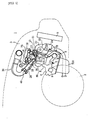
- Fig. 1 is a side view of the front portion of a vehicle carrying a four-stroke cycle engine
- Fig. 2 a schematic diagram showing an oil circulation route of the four-stroke cycle engine
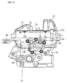
- Fig. 3 a plan view of a cylinder head with a head cover removed
- Fig. 4 a side view of the cylinder head with the head cover
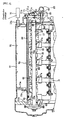
- Fig. 5 a longitudinal sectional view of the cylinder head with the head cover
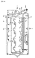
- Fig. 6 a bottom view of a baffle plate
- Fig. 7 a side view of the baffle plate of Fig. 6 as seen in the direction of an arrow A
- Fig. 8 a side view of the baffle plate of Fig. 6 as seen in the direction of an arrow B.
- an engine room 3 at the front side of front wheels 2, and in the engine room 3 is mounted a four-stroke cycle engine 4, in front of which is disposed a radiator 5.
- the engine 4 is of a two cylinder four-stroke cycle type, and at the bottom of an engine body 6 is provided an oil pan 700.
- the engine body 6 is provided, laterally of the vehicle, with a crank shaft 7, at the front and rear sides of which are provided balancer shafts 8, 9 laterally of the vehicle.
- a cylinder block 90 constituting the engine body 6 On a cylinder block 90 constituting the engine body 6 is mounted a cylinder head 10, and in the cylinder head 10 are formed branched exhaust passages 11, 12 and branched intake passages 13, 14 for each cylinder.
- the branched exhaust passages 11, 12 and the branched intake passages 13, 14 are opened and closed by corresponding exhaust valves 15 and corresponding intake valves 16, respectively, and the exhaust and intake valves 15, 16 are driven by cams 19, 20 provided on cam shafts 17, 18.
- the branched exhaust passages 11, 12 are joined together to form an exhaust passage 21, to which is connected an exhaust pipe 22.
- Exhaust pipes 22 connected to the respective cylinders are assembled into an exhaust pipe 23, which extends from the front side of the engine body 6 rearwardly thereunder.
- a catalyst 24 is provided in the exhaust pipe 23 in the exhaust pipe 23 in the exhaust pipe 23 in the exhaust pipe 23 in the exhaust pipe 23 in the exhaust pipe 23 in the exhaust pipe 23 in the exhaust pipe 23.
- the branched intake passages 13, 14 are joined together to form an intake passage 25, upstream of which is provided a throttle body 26 on the cylinder head 10.
- the throttle body 26 has exhaust passages 28 in communication with the exhaust passages 25 in the respective cylinders, and is also adapted to connect an intake manifold 30.
- a throttle valve 40 for controlling the flow rate for each intake passage 28.
- the throttle valve 40 is controlled according to information of engine speed and throttle opening.
- an oil pump 50 On one side of the engine body 6 is provided an oil pump 50, and operation of the oil pump causes oil collected in the oil pan 700 to be pumped up through an oil passage 51 and supplied to oil passages 57, 58 formed in the cam shafts 17, 18 from an oil passage 52 in the cylinder block 90, an oil passage 53 in the cylinder head 10, and an oil passage 54 extending perpendicular to the cam shafts 17, 18, through branched passages 55, 56.
- the cam shafts 17, 18 are journaled for rotation on bearings 62, 63 with cam caps 60, 61 and formed with injection holes 17a, 18a, in communication with oil passages 57, 58, corresponding to bearings 62, 63. Oil is supplied to bearings 62, 63 through the injection holes 17a, 18a.
- a filter 59 In the oil passage 54 is provided a filter 59, through which oil is fed to an oil control valve 65.
- a housing 66 of the oil control valve 65 is attached to the side wall of the cylinder head 10, and the oil control valve 65 is adapted to control oil supply from an oil passage 67 to a variable valve 68 so as to control a variable cam mechanism (not shown) in response to engine speed.
- an oil passage 69 is formed extending upwardly from the filter 59, and the oil passage 69 is in communication with an induction pipe 71 of a baffle plate unit 70.
- a ring pipe 72 is connected to the induction pipe 71, and the induction pipe 71 and the ring pipe 72 are fitted to the baffle plate 73 with fixtures 73a.
- One end 71a of the induction pipe 71 is connected to the cylinder head 10 through a sealing member 74 or an O-ring, and the other end is fitted in a cylinder head cover 75.
- the baffle plate 73 is fastened with screws 76 to the cylinder head cover 75, a portion 73b of which is fixed to the same by caulking.
- the baffle plate 73 is provided with a baffle board 73c, which is disposed opposite to a baffle section 75a protruding inwardly of the cylinder head cover 75, so that a maze is formed in a cam chamber 77 to separate oil particles.
- the cylinder head cover 75 has a discharge section 75a. Blow-by gas leaking from a combustion chamber 78 into a crank chamber (not shown) is introduced into the cam chamber 77 within the cylinder head cover 75, and oil particles in the blow-by gas is separated by the baffle plate 73. The blow-by gas without oil particles is returned to the intake passage 28 from the discharge section 75a through a circulation passage 79.
- An oil passage for supplying lubricating oil to cam shafts 17, 18 is formed of the induction pipe 71 and the ring pipe 72, and the oil flow rate is regulated by an orifice 71c in the induction pipe 71.
- the ring pipe 72 is bent such that straight sections 72a, 72b are disposed above the cam shafts, and a bent section 72c is adapted to decrease the magnitude of the bend of the oil passage so as to reduce pressure loss.
- the straight sections 72a, 72b are formed with injection holes 72d, 723, corresponding to cams 19, 20, through which oil is injected toward the cams 19, 20.
- straight section 72b on the intake side and the straight section 72a on the exhaust side are connected to form a continuous oil passage 80, so that oil pressure at the pipe end is increased and the rising characteristics of the oil pressure is improved, providing uniformity in oil pressure between intake and exhaust sides.
- the baffle plate 73 within the cylinder head cover 75 is provided with the oil passage 80 formed by the induction pipe 71 and the ring pipe 72, therefore the degree of freedom in designing the oil passage 80 is increased and pressure loss in the oil passage 80 can be reduced. Further, the oil passage 80 formed by the induction pipe 71 and the ring pipe 72 can be attached and detached together with the baffle plate 73, resulting in improved workability, and since it is not attached directly to the valve drive system, vibration on the oil passage 80 can be reduced, improving reliability.
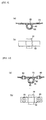
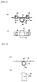
- Fig. 9 through Fig. 12 show embodiments of the baffle plate unit, in which the oil passage 80 is constituted by a pipe 81 attached to the baffle plate 73 and injection holes 81a are formed on the pipe 81.
- fixtures 82 are welded to the baffle plate 73 for attachment of the pipe 81.
- fixtures 82 are riveted to the baffle plate 73 with rivets 83 for attachment of the pipe 81.
- fixtures 82 are fastened to the baffle plate 73 with bolts 84 and nuts 85 for attachment of the pipe 81.
- the pipe 81 is attached to the baffle plate 73 directly by welding.
- the oil passage 80 is constituted by the pipe 81 attached to the baffle plate 73, therefore the degree to freedom in designing the oil passage 80 is increased and pressure loss in the oil passage can be reduced.
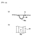
- Fig. 13 shows an embodiment of the baffle plate unit 70, in which the oil passage is constituted by the baffle plate 73, and a press-formed sheet metal 86 fixed to the baffle plate 73, and the oil passage can be made from a small number of components.
- this embodiment is exemplified by a press-formed sheet metal 86 brazed to the baffle plate 73, adhesives for metal parts may be used for bonding.
- the metal plate 86 has injection holes.
- an oil passage is provided on a baffle plate within a cylinder head cover, therefore the degree of freedom in designing the oil passage is increased and power loss in the oil passage can be reduced. Further, it can be attached and detached together with the baffle plate, resulting in improved workability, and since it is not attached directly to the valve drive system, vibration on the oil passage can be reduced, improving reliability.
- an oil passage may be constituted by a pipe attached to a baffle plate, therefore the degree of freedom in designing the oil passage is increased and power loss in the oil passage can be reduced.
- an oil passage may be constituted by a baffle plate, and a press-formed sheet metal fixed to the baffle plate, therefore the oil passage can be made from a smaller number of components.
Landscapes
- Engineering & Computer Science (AREA)
- Mechanical Engineering (AREA)
- General Engineering & Computer Science (AREA)
- Lubrication Of Internal Combustion Engines (AREA)
- Lubrication Details And Ventilation Of Internal Combustion Engines (AREA)
- Cylinder Crankcases Of Internal Combustion Engines (AREA)
Abstract
Description
- This invention relates to a four-stroke cycle engine having intake and exhaust passages openable to a combustion chamber by means of intake and exhaust valves, respectively, said intake and exhaust valves being driven by cams on cam shafts, blow-by gas leaking from said combustion chamber into a crank chamber being introduced into a space within a cylinder head cover and returned to said intake passages from a circulation passage through a baffle plate within said cylinder head cover
- A four-stroke cycle engine has been used, for example, having intake and exhaust passages open to a combustion chamber, and intake and exhaust valves for opening and closing the intake and exhaust passages, respectively, the intake and exhaust valves being driven by cams on cam shafts, blow-by gas leaking from the combustion chamber into a crank chamber being introduced into a space within a cylinder head cover and returned to the intake passages from a circulation passage through a baffle plate within the cylinder head cover.
- For such a four-stroke cycle engine, an idea is suggested that an oil passage is formed in a rigid body connecting cam caps, and oil is injected from injection holes for lubrication of a cam shaft, but such a system has a smaller degree of freedom in designing the configuration of the oil passage.
- Also, it is suggested that the oil passage is formed of a pipe, and in the pipe there are opened small injection holes, from which oil is injected to lubricate cam shafts. However, because of the pipe being fastened to the cylinder head by means of stays welded to the pipe, together with cam caps, workability is poor for attachment and detachment. In addition, since the pipe is attached directly to the cylinder head, components in the oil passage is apt to be subjected to vibration due to the valve drive system.
- Accordingly, it is an objective of the present invention to provide a four-stroke cycle engine as indicated above facilitating improvements of the degree of freedom in designing an oil passage, improved workability for attachment and detachment, improved reliability due to reduction of vibration on the oil passage, and reduced pressure loss in the same.
- According to the present invention, this objective is solved for a four-stroke cycle engine as indicated above in that said baffle plate within said cylinder head cover is provided with an oil passage for supplying lubricating oil to said cam shafts.
- According to the invention, an oil passage is provided on a baffle plate within a cylinder head cover. Therefore, the degree of freedom in designing the oil passage is improved and pressure loss in the oil passage can be reduced. Further, it can be attached and detached together with the baffle plate, resulting in improved workability, and since it is not attached directly to the valve drive system, vibration on the oil passage can be reduced, improving reliability.
- Another embodiment of the invention is characterized in that said oil passage is constituted by a pipe attached to said baffle plate.
- According to this embodiment, the oil passage is constituted by a pipe attached to the baffle plate, therefore the degree of freedom in designing the oil passage is improved and pressure loss in the oil passage can be reduced.
- A further embodiment of the invention is characterized in that said oil passage is constituted by said baffle plate, and a press-formed sheet metal fixed to said baffle plate.
- Accordingly, the oil passage is constituted by the baffle plate, and a press-formed sheet metal fixed to the baffle plate, therefore the oil passage can be made from a small number of components.
- Other preferred embodiments of the present invention are laid down in further dependent claims.
- In the following, the present invention is explained in greater detail with respect to several embodiments thereof in conjunction with the accompanying drawings, wherein:
- Fig. 1 is a side view of the front portion of a vehicle carrying a four-stroke cycle engine;
- Fig. 2 is a schematic diagram showing an oil circulation route of the four-stroke cycle engine;
- Fig. 3 is a plan view of a cylinder head with a head cover removed;
- Fig. 4 is a side view of the cylinder head with the head cover;
- Fig. 5 is a longitudinal sectional view of the cylinder head with the head cover;
- Fig. 6 is a bottom view of a baffle plate;
- Fig. 7 is a side view of the baffle plate of Fig. 6 as seen in the direction of an arrow A;
- Fig. 8 is a side view of the baffle plate of Fig. 6 as seen in the direction of an arrow B;
- Fig. 9 is a view showing an embodiment of a baffle plate unit;
- Fig. 10 is a view showing another embodiment of the baffle plate unit;
- Fig. 11 is a view showing still another embodiment of the baffle plate unit;
- Fig. 12 is a view showing yet another embodiment of the baffle plate unit; and
- Fig. 13 is a view showing further embodiment of the baffle plate unit.
-
- Now, an embodiment of a four-stroke cycle engine of this invention will be described below with reference to the accompanying drawings.
- Fig. 1 is a side view of the front portion of a vehicle carrying a four-stroke cycle engine; Fig. 2 a schematic diagram showing an oil circulation route of the four-stroke cycle engine; Fig. 3 a plan view of a cylinder head with a head cover removed; Fig. 4 a side view of the cylinder head with the head cover; Fig. 5 a longitudinal sectional view of the cylinder head with the head cover; Fig. 6 a bottom view of a baffle plate; Fig. 7 a side view of the baffle plate of Fig. 6 as seen in the direction of an arrow A; and Fig. 8 a side view of the baffle plate of Fig. 6 as seen in the direction of an arrow B.
- In the front portion of a
vehicle 1 is provided anengine room 3 at the front side offront wheels 2, and in theengine room 3 is mounted a four-stroke cycle engine 4, in front of which is disposed aradiator 5. Theengine 4 is of a two cylinder four-stroke cycle type, and at the bottom of anengine body 6 is provided anoil pan 700. Theengine body 6 is provided, laterally of the vehicle, with a crank shaft 7, at the front and rear sides of which are providedbalancer shafts - On a
cylinder block 90 constituting theengine body 6 is mounted acylinder head 10, and in thecylinder head 10 are formed branched exhaust passages 11, 12 and branched intake passages 13, 14 for each cylinder. The branched exhaust passages 11, 12 and the branched intake passages 13, 14 are opened and closed bycorresponding exhaust valves 15 andcorresponding intake valves 16, respectively, and the exhaust andintake valves cams cam shafts - The branched exhaust passages 11, 12 are joined together to form an
exhaust passage 21, to which is connected anexhaust pipe 22.Exhaust pipes 22 connected to the respective cylinders are assembled into anexhaust pipe 23, which extends from the front side of theengine body 6 rearwardly thereunder. In addition, in theexhaust pipe 23 is provided acatalyst 24. - The branched intake passages 13, 14 are joined together to form an
intake passage 25, upstream of which is provided athrottle body 26 on thecylinder head 10. Thethrottle body 26 hasexhaust passages 28 in communication with theexhaust passages 25 in the respective cylinders, and is also adapted to connect anintake manifold 30. - In the
cylinder head 10 are disposedinjectors 35. In thethrottle body 26 is provided athrottle valve 40 for controlling the flow rate for eachintake passage 28. Thethrottle valve 40 is controlled according to information of engine speed and throttle opening. - On one side of the
engine body 6 is provided anoil pump 50, and operation of the oil pump causes oil collected in theoil pan 700 to be pumped up through an oil passage 51 and supplied tooil passages cam shafts oil passage 52 in thecylinder block 90, anoil passage 53 in thecylinder head 10, and anoil passage 54 extending perpendicular to thecam shafts branched passages cam shafts bearings cam caps injection holes 17a, 18a, in communication withoil passages bearings bearings injection holes 17a, 18a. - In the
oil passage 54 is provided afilter 59, through which oil is fed to anoil control valve 65. Ahousing 66 of theoil control valve 65 is attached to the side wall of thecylinder head 10, and theoil control valve 65 is adapted to control oil supply from anoil passage 67 to avariable valve 68 so as to control a variable cam mechanism (not shown) in response to engine speed. - In addition, an
oil passage 69 is formed extending upwardly from thefilter 59, and theoil passage 69 is in communication with aninduction pipe 71 of abaffle plate unit 70. Aring pipe 72 is connected to theinduction pipe 71, and theinduction pipe 71 and thering pipe 72 are fitted to thebaffle plate 73 withfixtures 73a. - One
end 71a of theinduction pipe 71 is connected to thecylinder head 10 through a sealing member 74 or an O-ring, and the other end is fitted in acylinder head cover 75. Thebaffle plate 73 is fastened withscrews 76 to thecylinder head cover 75, aportion 73b of which is fixed to the same by caulking. - The
baffle plate 73 is provided with abaffle board 73c, which is disposed opposite to abaffle section 75a protruding inwardly of thecylinder head cover 75, so that a maze is formed in acam chamber 77 to separate oil particles. Thecylinder head cover 75 has adischarge section 75a. Blow-by gas leaking from acombustion chamber 78 into a crank chamber (not shown) is introduced into thecam chamber 77 within thecylinder head cover 75, and oil particles in the blow-by gas is separated by thebaffle plate 73. The blow-by gas without oil particles is returned to theintake passage 28 from thedischarge section 75a through acirculation passage 79. - An oil passage for supplying lubricating oil to
cam shafts induction pipe 71 and thering pipe 72, and the oil flow rate is regulated by anorifice 71c in theinduction pipe 71. In addition, thering pipe 72 is bent such thatstraight sections bent section 72c is adapted to decrease the magnitude of the bend of the oil passage so as to reduce pressure loss. Thestraight sections injection holes 72d, 723, corresponding tocams cams straight section 72b on the intake side and thestraight section 72a on the exhaust side are connected to form acontinuous oil passage 80, so that oil pressure at the pipe end is increased and the rising characteristics of the oil pressure is improved, providing uniformity in oil pressure between intake and exhaust sides. - Thus, the
baffle plate 73 within thecylinder head cover 75 is provided with theoil passage 80 formed by theinduction pipe 71 and thering pipe 72, therefore the degree of freedom in designing theoil passage 80 is increased and pressure loss in theoil passage 80 can be reduced. Further, theoil passage 80 formed by theinduction pipe 71 and thering pipe 72 can be attached and detached together with thebaffle plate 73, resulting in improved workability, and since it is not attached directly to the valve drive system, vibration on theoil passage 80 can be reduced, improving reliability. - Fig. 9 through Fig. 12 show embodiments of the baffle plate unit, in which the
oil passage 80 is constituted by apipe 81 attached to thebaffle plate 73 and injection holes 81a are formed on thepipe 81. In the embodiment of Fig. 9,fixtures 82 are welded to thebaffle plate 73 for attachment of thepipe 81. In the embodiment of Fig. 10,fixtures 82 are riveted to thebaffle plate 73 withrivets 83 for attachment of thepipe 81. In the embodiment of Fig. 11,fixtures 82 are fastened to thebaffle plate 73 withbolts 84 andnuts 85 for attachment of thepipe 81. In the embodiment of Fig. 12, thepipe 81 is attached to thebaffle plate 73 directly by welding. - Thus, the
oil passage 80 is constituted by thepipe 81 attached to thebaffle plate 73, therefore the degree to freedom in designing theoil passage 80 is increased and pressure loss in the oil passage can be reduced. - Fig. 13 shows an embodiment of the
baffle plate unit 70, in which the oil passage is constituted by thebaffle plate 73, and a press-formedsheet metal 86 fixed to thebaffle plate 73, and the oil passage can be made from a small number of components. Although this embodiment is exemplified by a press-formedsheet metal 86 brazed to thebaffle plate 73, adhesives for metal parts may be used for bonding. Themetal plate 86 has injection holes. - As described above, an oil passage is provided on a baffle plate within a cylinder head cover, therefore the degree of freedom in designing the oil passage is increased and power loss in the oil passage can be reduced. Further, it can be attached and detached together with the baffle plate, resulting in improved workability, and since it is not attached directly to the valve drive system, vibration on the oil passage can be reduced, improving reliability.
- Further, an oil passage may be constituted by a pipe attached to a baffle plate, therefore the degree of freedom in designing the oil passage is increased and power loss in the oil passage can be reduced.
- Moreover, an oil passage may be constituted by a baffle plate, and a press-formed sheet metal fixed to the baffle plate, therefore the oil passage can be made from a smaller number of components.
Claims (10)
- A four-stroke cycle engine (4) having intake and exhaust passages (11,12,13,14) openable to a combustion chamber by means of intake and exhaust valves (15,16), respectively, said intake and exhaust valves (15,16) being driven by cams (19,20) on cam shafts (17,18), blow-by gas leaking from said combustion chamber (78) into a crank chamber being introduced into a space within a cylinder head cover (75) and returned to said intake passages (11,12) from a circulation passage (79) through a baffle plate (73) within said cylinder head cover (75), characterized in that said baffle plate (73) within said cylinder head cover (75) is provided with an oil passage (80) for supplying lubricating oil to said cam shafts(17,18).
- The four-stroke cycle engine (4) according to claim 1, wherein said oil passage (80) is constituted by a pipe (81) attached to said baffle plate (73).
- The four-stroke cycle engine (4) according to claim 1, wherein said oil passage (80) is constituted by said baffle plate (73), and a sheet metal (86) fixed to said baffle plate (73).
- The four-stroke cycle engine (4) according to at least one of the preceding claims 1 to 3, characterized in that the baffle plate (73) is provided with a baffle board (73c), which is disposed opposite to a baffle section (75a) protruding inwardly to a cylinder head cover (75) such that a maze is formed in a cam chamber (77) to separate oil particles.
- The four-stroke cycle engine (4) according to claim 4, characterized in that blow-gas leaking from the combustion chamber (78) into a crank chamber is introducable into the cam chamber (77) within the cylinder head cover (75), whereas the baffle plate (73) separates the oil particles contained in the blow-by gas.
- The four-stroke cycle engine (4) according to claim 5, characterized in that the blow-by gas being separated from oil particles is returnable to an intake passage (28) from a discharge section (75a) through a circulation passage (79).
- The four-stroke cycle engine (4) according to at least one of the preceding claims 2 or 4 to 6, characterized in that said pipe (81) being attached to the baffle plate (73) by welding or by fixtures (82), which fixtures (82) are welded, riveted or fastened with bolts (84) and nuts (85).
- The four-stroke cycle engine (4) according to at least one of the preceding claims 3 to 6, characterized in that said sheet metal is a press-formed sheet metal (86).
- The four-stroke cycle engine (4) according to claim 8, characterized in that said press-formed sheet metal (86) being brazed or bonded with adhesive to the baffle plate (73).
- The four-stroke cycle engine (4) according to claim 8 or 9, characterized in that said press-formed sheet metal (86) is provided with injection holes.
Applications Claiming Priority (2)
| Application Number | Priority Date | Filing Date | Title |
|---|---|---|---|
| JP17970899 | 1999-06-25 | ||
| JP17970899A JP4446105B2 (en) | 1999-06-25 | 1999-06-25 | 4-cycle engine |
Publications (3)
| Publication Number | Publication Date |
|---|---|
| EP1063400A2 true EP1063400A2 (en) | 2000-12-27 |
| EP1063400A3 EP1063400A3 (en) | 2002-04-17 |
| EP1063400B1 EP1063400B1 (en) | 2005-03-30 |
Family
ID=16070496
Family Applications (1)
| Application Number | Title | Priority Date | Filing Date |
|---|---|---|---|
| EP00112406A Expired - Lifetime EP1063400B1 (en) | 1999-06-25 | 2000-06-09 | Four-stroke cycle engine |
Country Status (4)
| Country | Link |
|---|---|
| US (1) | US6378483B1 (en) |
| EP (1) | EP1063400B1 (en) |
| JP (1) | JP4446105B2 (en) |
| DE (1) | DE60019025T2 (en) |
Cited By (2)
| Publication number | Priority date | Publication date | Assignee | Title |
|---|---|---|---|---|
| EP1541815A3 (en) * | 2003-12-09 | 2008-12-24 | Nissan Motor Company, Limited | Variable valve actuating mechanism for internal combustion engine |
| DE102010034934B4 (en) | 2010-03-10 | 2023-01-12 | GM Global Technology Operations LLC (n. d. Ges. d. Staates Delaware) | Engine with a camshaft lubrication manifold |
Families Citing this family (10)
| Publication number | Priority date | Publication date | Assignee | Title |
|---|---|---|---|---|
| US6796283B1 (en) * | 2003-06-24 | 2004-09-28 | Ford Global Technologies, Llc | Oiling system for an internal combustion engine |
| JP2007127014A (en) * | 2005-11-02 | 2007-05-24 | Kojima Press Co Ltd | Cylinder head cover and feeding structure for lubrication oil to cam shaft |
| JP5082959B2 (en) * | 2008-03-17 | 2012-11-28 | トヨタ自動車株式会社 | Lubrication structure of internal combustion engine |
| US8011338B2 (en) * | 2008-09-11 | 2011-09-06 | Ford Global Technologies, Llc | Camcover oil separator |
| DE102011075666B4 (en) * | 2011-05-11 | 2018-07-12 | Ford Global Technologies, Llc | Method for heating the engine oil of an internal combustion engine and internal combustion engine for carrying out such a method |
| JP5509289B2 (en) * | 2012-10-05 | 2014-06-04 | 本田技研工業株式会社 | Vehicle drive device |
| US9027522B2 (en) | 2012-10-17 | 2015-05-12 | Ford Global Technologies, Llc | Camshaft with internal oil filter |
| EP3173592B1 (en) * | 2015-11-24 | 2021-01-06 | Aktiebolaget SKF | Cam follower roller device with lubricant supply holes and lubricating method |
| JP6909585B2 (en) * | 2017-01-31 | 2021-07-28 | ダイハツ工業株式会社 | Lubrication device for camshafts of internal combustion engines |
| EP3623592A1 (en) * | 2018-09-17 | 2020-03-18 | Uwe Eisenbeis | Variable valvetrain having lubricant supply system |
Family Cites Families (14)
| Publication number | Priority date | Publication date | Assignee | Title |
|---|---|---|---|---|
| JPS57163141A (en) | 1981-03-31 | 1982-10-07 | Yamaha Motor Co Ltd | Cylinder head clamping structure in internal- combustion engine |
| US4602595A (en) * | 1984-03-01 | 1986-07-29 | Aisin Seiki Kabushiki Kaisha | Oil separator for internal combustion engine |
| US4592314A (en) | 1985-04-18 | 1986-06-03 | Yamaha Hatsudoki Kabushiki Kaisha | Valve actuating mechanism for internal combustion engine |
| DE3520876C1 (en) * | 1985-06-11 | 1986-09-04 | Peter Hufnagel GmbH, 8500 Nürnberg | Device for feeding lubricating oil to the friction areas of a cam shaft. |
| JPS6218314U (en) * | 1985-07-19 | 1987-02-03 | ||
| US4754729A (en) * | 1985-10-11 | 1988-07-05 | Honda Giken Kogyo Kabushiki Kaisha | Camshaft support assembly for valve operating mechanism in an internal combustion engines |
| CA1330026C (en) * | 1987-12-28 | 1994-06-07 | Tomonori Niizato | Lubricant supplying system for dohc type multi-cylinder internal combustion engine |
| JP2647951B2 (en) * | 1989-02-28 | 1997-08-27 | ヤマハ発動機株式会社 | Blow-by gas recovery device for vehicle engine |
| US5161495A (en) | 1989-07-14 | 1992-11-10 | Yamaha Hatsudoki Kabushiki Kaisha | Lubrication arrangement for engine |
| USRE35382E (en) | 1989-07-14 | 1996-11-26 | Yamaha Hatsudoki Kabushiki Kaisha | Lubrication arrangement for engine |
| DE69414557T2 (en) | 1994-06-15 | 1999-04-01 | Yamaha Hatsudoki K.K., Iwata, Shizuoka | Cylinder head arrangement for a multi-valve internal combustion engine with an overhead camshaft |
| DE19526285A1 (en) * | 1995-07-19 | 1997-01-23 | Schaeffler Waelzlager Kg | Device for lubricant supply of valve gear of internal combustion engine |
| DE19700733C2 (en) * | 1997-01-11 | 2001-11-22 | Bayerische Motoren Werke Ag | Crankcase ventilation through the cylinder head cover with integrated additional functions |
| JP2000120422A (en) | 1998-10-12 | 2000-04-25 | Yamaha Motor Co Ltd | Engine camshaft lubrication structure |
-
1999
- 1999-06-25 JP JP17970899A patent/JP4446105B2/en not_active Expired - Lifetime
-
2000
- 2000-06-09 DE DE60019025T patent/DE60019025T2/en not_active Expired - Lifetime
- 2000-06-09 EP EP00112406A patent/EP1063400B1/en not_active Expired - Lifetime
- 2000-06-26 US US09/603,026 patent/US6378483B1/en not_active Expired - Lifetime
Non-Patent Citations (1)
| Title |
|---|
| None |
Cited By (2)
| Publication number | Priority date | Publication date | Assignee | Title |
|---|---|---|---|---|
| EP1541815A3 (en) * | 2003-12-09 | 2008-12-24 | Nissan Motor Company, Limited | Variable valve actuating mechanism for internal combustion engine |
| DE102010034934B4 (en) | 2010-03-10 | 2023-01-12 | GM Global Technology Operations LLC (n. d. Ges. d. Staates Delaware) | Engine with a camshaft lubrication manifold |
Also Published As
| Publication number | Publication date |
|---|---|
| DE60019025D1 (en) | 2005-05-04 |
| DE60019025T2 (en) | 2005-08-11 |
| US6378483B1 (en) | 2002-04-30 |
| JP2001012223A (en) | 2001-01-16 |
| JP4446105B2 (en) | 2010-04-07 |
| EP1063400A3 (en) | 2002-04-17 |
| EP1063400B1 (en) | 2005-03-30 |
Similar Documents
| Publication | Publication Date | Title |
|---|---|---|
| EP1063400B1 (en) | Four-stroke cycle engine | |
| EP3760462B1 (en) | Hybrid vehicle | |
| EP3760461B1 (en) | Hybrid vehicle | |
| JP2013083190A (en) | Support structure of auxiliary machine of internal combustion engine | |
| EP3760460B1 (en) | Hybrid vehicle | |
| US6332441B1 (en) | Assembling arrangement for tensioner and hydraulic control valve | |
| JP2001041120A (en) | Intake pipe for internal combustion engine | |
| JP2002168106A (en) | Refueling structure for valve train of internal combustion engine | |
| JP2010127073A (en) | Internal combustion engine | |
| US7267094B2 (en) | Lubrication system of small vehicle engine | |
| EP3760844B1 (en) | Straddle vehicle | |
| EP0987416A2 (en) | V-type internal combustion engine for motorcycle | |
| EP0987413B1 (en) | V-type internal combustion engine for motorcycle | |
| EP3786473B1 (en) | Straddle vehicle | |
| JPH10141154A (en) | Engine intake manifold | |
| JP3786066B2 (en) | Engine intake system | |
| JP2019215007A (en) | Cooling structure of internal combustion engine | |
| CA2457421C (en) | Exhaust gas purifying device for engines | |
| JP4403026B2 (en) | Lubrication structure of fuel injection pump | |
| EP0987414B1 (en) | V-type internal combustion engine for vehicle | |
| KR100413544B1 (en) | Vertical engine | |
| CN210829494U (en) | Internal combustion engine for vehicle | |
| JPH1182205A (en) | Air vent device for auxiliary fuel tank in power unit | |
| CN100390428C (en) | Drive system attached to the engine | |
| JP2529104Y2 (en) | Lubricating oil supply device for internal combustion engine |
Legal Events
| Date | Code | Title | Description |
|---|---|---|---|
| PUAI | Public reference made under article 153(3) epc to a published international application that has entered the european phase |
Free format text: ORIGINAL CODE: 0009012 |
|
| AK | Designated contracting states |
Kind code of ref document: A2 Designated state(s): AT BE CH CY DE DK ES FI FR GB GR IE IT LI LU MC NL PT SE Kind code of ref document: A2 Designated state(s): DE ES FR GB IT |
|
| AX | Request for extension of the european patent |
Free format text: AL;LT;LV;MK;RO;SI |
|
| PUAL | Search report despatched |
Free format text: ORIGINAL CODE: 0009013 |
|
| RIC1 | Information provided on ipc code assigned before grant |
Free format text: 7F 02B 75/20 A, 7F 01M 13/04 B, 7F 01M 9/10 B, 7F 01M 11/02 B |
|
| AK | Designated contracting states |
Kind code of ref document: A3 Designated state(s): AT BE CH CY DE DK ES FI FR GB GR IE IT LI LU MC NL PT SE |
|
| AX | Request for extension of the european patent |
Free format text: AL;LT;LV;MK;RO;SI |
|
| 17P | Request for examination filed |
Effective date: 20021011 |
|
| AKX | Designation fees paid |
Free format text: DE ES FR GB IT |
|
| 17Q | First examination report despatched |
Effective date: 20030416 |
|
| GRAP | Despatch of communication of intention to grant a patent |
Free format text: ORIGINAL CODE: EPIDOSNIGR1 |
|
| GRAS | Grant fee paid |
Free format text: ORIGINAL CODE: EPIDOSNIGR3 |
|
| GRAA | (expected) grant |
Free format text: ORIGINAL CODE: 0009210 |
|
| AK | Designated contracting states |
Kind code of ref document: B1 Designated state(s): DE ES FR GB IT |
|
| REG | Reference to a national code |
Ref country code: GB Ref legal event code: FG4D |
|
| REF | Corresponds to: |
Ref document number: 60019025 Country of ref document: DE Date of ref document: 20050504 Kind code of ref document: P |
|
| REG | Reference to a national code |
Ref country code: IE Ref legal event code: FG4D |
|
| PG25 | Lapsed in a contracting state [announced via postgrant information from national office to epo] |
Ref country code: ES Free format text: LAPSE BECAUSE OF FAILURE TO SUBMIT A TRANSLATION OF THE DESCRIPTION OR TO PAY THE FEE WITHIN THE PRESCRIBED TIME-LIMIT Effective date: 20050711 |
|
| PLBE | No opposition filed within time limit |
Free format text: ORIGINAL CODE: 0009261 |
|
| STAA | Information on the status of an ep patent application or granted ep patent |
Free format text: STATUS: NO OPPOSITION FILED WITHIN TIME LIMIT |
|
| ET | Fr: translation filed | ||
| 26N | No opposition filed |
Effective date: 20060102 |
|
| REG | Reference to a national code |
Ref country code: FR Ref legal event code: PLFP Year of fee payment: 17 |
|
| REG | Reference to a national code |
Ref country code: FR Ref legal event code: PLFP Year of fee payment: 18 |
|
| REG | Reference to a national code |
Ref country code: FR Ref legal event code: PLFP Year of fee payment: 19 |
|
| PGFP | Annual fee paid to national office [announced via postgrant information from national office to epo] |
Ref country code: IT Payment date: 20190624 Year of fee payment: 20 Ref country code: DE Payment date: 20190619 Year of fee payment: 20 |
|
| PGFP | Annual fee paid to national office [announced via postgrant information from national office to epo] |
Ref country code: FR Payment date: 20190619 Year of fee payment: 20 |
|
| PGFP | Annual fee paid to national office [announced via postgrant information from national office to epo] |
Ref country code: GB Payment date: 20190619 Year of fee payment: 20 |
|
| REG | Reference to a national code |
Ref country code: GB Ref legal event code: PE20 Expiry date: 20200608 |
|
| PG25 | Lapsed in a contracting state [announced via postgrant information from national office to epo] |
Ref country code: GB Free format text: LAPSE BECAUSE OF EXPIRATION OF PROTECTION Effective date: 20200608 |