EP1062704B1 - Prismatic battery housing - Google Patents
Prismatic battery housing Download PDFInfo
- Publication number
- EP1062704B1 EP1062704B1 EP99911113A EP99911113A EP1062704B1 EP 1062704 B1 EP1062704 B1 EP 1062704B1 EP 99911113 A EP99911113 A EP 99911113A EP 99911113 A EP99911113 A EP 99911113A EP 1062704 B1 EP1062704 B1 EP 1062704B1
- Authority
- EP
- European Patent Office
- Prior art keywords
- cover
- prismatic
- sides
- flange
- seal
- Prior art date
- Legal status (The legal status is an assumption and is not a legal conclusion. Google has not performed a legal analysis and makes no representation as to the accuracy of the status listed.)
- Expired - Lifetime
Links
- 238000003466 welding Methods 0.000 claims abstract description 15
- 238000000034 method Methods 0.000 claims abstract description 14
- 238000004891 communication Methods 0.000 claims description 6
- 239000002184 metal Substances 0.000 claims description 6
- 229910052751 metal Inorganic materials 0.000 claims description 6
- 238000007789 sealing Methods 0.000 claims description 5
- 239000003792 electrolyte Substances 0.000 claims description 4
- 238000003825 pressing Methods 0.000 claims description 4
- 238000012360 testing method Methods 0.000 claims description 3
- 238000004519 manufacturing process Methods 0.000 abstract description 2
- PXHVJJICTQNCMI-UHFFFAOYSA-N nickel Substances [Ni] PXHVJJICTQNCMI-UHFFFAOYSA-N 0.000 description 7
- 229910000975 Carbon steel Inorganic materials 0.000 description 4
- 239000010962 carbon steel Substances 0.000 description 4
- 229910052759 nickel Inorganic materials 0.000 description 4
- 230000000712 assembly Effects 0.000 description 3
- 238000000429 assembly Methods 0.000 description 3
- 239000000463 material Substances 0.000 description 3
- 239000011149 active material Substances 0.000 description 2
- 238000010276 construction Methods 0.000 description 2
- 239000012212 insulator Substances 0.000 description 2
- 238000004080 punching Methods 0.000 description 2
- 239000010935 stainless steel Substances 0.000 description 2
- 229910001220 stainless steel Inorganic materials 0.000 description 2
- 238000005452 bending Methods 0.000 description 1
- 230000001413 cellular effect Effects 0.000 description 1
- 230000001010 compromised effect Effects 0.000 description 1
- 239000000945 filler Substances 0.000 description 1
- 239000002654 heat shrinkable material Substances 0.000 description 1
- 238000003780 insertion Methods 0.000 description 1
- 230000037431 insertion Effects 0.000 description 1
- 239000000155 melt Substances 0.000 description 1
- 229910052987 metal hydride Inorganic materials 0.000 description 1
- -1 nickel metal hydride Chemical class 0.000 description 1
- 230000002093 peripheral effect Effects 0.000 description 1
- 230000002265 prevention Effects 0.000 description 1
- 230000035945 sensitivity Effects 0.000 description 1
- 125000006850 spacer group Chemical group 0.000 description 1
Images

Classifications
-
- H—ELECTRICITY
- H01—ELECTRIC ELEMENTS
- H01M—PROCESSES OR MEANS, e.g. BATTERIES, FOR THE DIRECT CONVERSION OF CHEMICAL ENERGY INTO ELECTRICAL ENERGY
- H01M50/00—Constructional details or processes of manufacture of the non-active parts of electrochemical cells other than fuel cells, e.g. hybrid cells
- H01M50/10—Primary casings; Jackets or wrappings
- H01M50/147—Lids or covers
-
- H—ELECTRICITY
- H01—ELECTRIC ELEMENTS
- H01M—PROCESSES OR MEANS, e.g. BATTERIES, FOR THE DIRECT CONVERSION OF CHEMICAL ENERGY INTO ELECTRICAL ENERGY
- H01M50/00—Constructional details or processes of manufacture of the non-active parts of electrochemical cells other than fuel cells, e.g. hybrid cells
- H01M50/10—Primary casings; Jackets or wrappings
- H01M50/172—Arrangements of electric connectors penetrating the casing
- H01M50/174—Arrangements of electric connectors penetrating the casing adapted for the shape of the cells
-
- H—ELECTRICITY
- H01—ELECTRIC ELEMENTS
- H01M—PROCESSES OR MEANS, e.g. BATTERIES, FOR THE DIRECT CONVERSION OF CHEMICAL ENERGY INTO ELECTRICAL ENERGY
- H01M50/00—Constructional details or processes of manufacture of the non-active parts of electrochemical cells other than fuel cells, e.g. hybrid cells
- H01M50/10—Primary casings; Jackets or wrappings
- H01M50/102—Primary casings; Jackets or wrappings characterised by their shape or physical structure
- H01M50/103—Primary casings; Jackets or wrappings characterised by their shape or physical structure prismatic or rectangular
-
- H—ELECTRICITY
- H01—ELECTRIC ELEMENTS
- H01M—PROCESSES OR MEANS, e.g. BATTERIES, FOR THE DIRECT CONVERSION OF CHEMICAL ENERGY INTO ELECTRICAL ENERGY
- H01M50/00—Constructional details or processes of manufacture of the non-active parts of electrochemical cells other than fuel cells, e.g. hybrid cells
- H01M50/10—Primary casings; Jackets or wrappings
- H01M50/147—Lids or covers
- H01M50/166—Lids or covers characterised by the methods of assembling casings with lids
- H01M50/169—Lids or covers characterised by the methods of assembling casings with lids by welding, brazing or soldering
-
- H—ELECTRICITY
- H01—ELECTRIC ELEMENTS
- H01M—PROCESSES OR MEANS, e.g. BATTERIES, FOR THE DIRECT CONVERSION OF CHEMICAL ENERGY INTO ELECTRICAL ENERGY
- H01M50/00—Constructional details or processes of manufacture of the non-active parts of electrochemical cells other than fuel cells, e.g. hybrid cells
- H01M50/10—Primary casings; Jackets or wrappings
- H01M50/172—Arrangements of electric connectors penetrating the casing
- H01M50/174—Arrangements of electric connectors penetrating the casing adapted for the shape of the cells
- H01M50/176—Arrangements of electric connectors penetrating the casing adapted for the shape of the cells for prismatic or rectangular cells
-
- H—ELECTRICITY
- H01—ELECTRIC ELEMENTS
- H01M—PROCESSES OR MEANS, e.g. BATTERIES, FOR THE DIRECT CONVERSION OF CHEMICAL ENERGY INTO ELECTRICAL ENERGY
- H01M50/00—Constructional details or processes of manufacture of the non-active parts of electrochemical cells other than fuel cells, e.g. hybrid cells
- H01M50/30—Arrangements for facilitating escape of gases
- H01M50/317—Re-sealable arrangements
- H01M50/325—Re-sealable arrangements comprising deformable valve members, e.g. elastic or flexible valve members
-
- H—ELECTRICITY
- H01—ELECTRIC ELEMENTS
- H01M—PROCESSES OR MEANS, e.g. BATTERIES, FOR THE DIRECT CONVERSION OF CHEMICAL ENERGY INTO ELECTRICAL ENERGY
- H01M50/00—Constructional details or processes of manufacture of the non-active parts of electrochemical cells other than fuel cells, e.g. hybrid cells
- H01M50/60—Arrangements or processes for filling or topping-up with liquids; Arrangements or processes for draining liquids from casings
- H01M50/609—Arrangements or processes for filling with liquid, e.g. electrolytes
- H01M50/627—Filling ports
- H01M50/636—Closing or sealing filling ports, e.g. using lids
- H01M50/645—Plugs
-
- Y—GENERAL TAGGING OF NEW TECHNOLOGICAL DEVELOPMENTS; GENERAL TAGGING OF CROSS-SECTIONAL TECHNOLOGIES SPANNING OVER SEVERAL SECTIONS OF THE IPC; TECHNICAL SUBJECTS COVERED BY FORMER USPC CROSS-REFERENCE ART COLLECTIONS [XRACs] AND DIGESTS
- Y02—TECHNOLOGIES OR APPLICATIONS FOR MITIGATION OR ADAPTATION AGAINST CLIMATE CHANGE
- Y02E—REDUCTION OF GREENHOUSE GAS [GHG] EMISSIONS, RELATED TO ENERGY GENERATION, TRANSMISSION OR DISTRIBUTION
- Y02E60/00—Enabling technologies; Technologies with a potential or indirect contribution to GHG emissions mitigation
- Y02E60/10—Energy storage using batteries
Definitions
- This invention relates to batteries with prismatic housings, and their construction.
- Prismatic cells are prismatic rather than circular in cross-section.
- Examples of such prismatic cells include rechargeable F6 nickel metal hydride (NiMH) cells currently used in portable electronics equipment, such as cellular phones, which have rectangular cross-sections.
- the housings of such prismatic cells typically include a deep drawn (or longitudinally seamed) can which is capped with a rigid, flat plate cover assembly having one or more electrical contacts. The cover is typically pressed down into the prismatic, open end of the can until the upper edge of the cover is slightly below the upper edge of the can, and then welded in place (e.g., by laser welding) to seal the cell.
- Housing materials include stainless steel or nickel plated cold rolled carbon steel (CRS).
- the documents GB-A-202088 , JP-A-57074964 and FR-A-2359515 disclose prismatic batteries with electrically conductive housing formed by welding a housing cover between the opposing sides of a prismatic can having an open end.
- Precise tolerancing of the can and cover are required to provide intimate contact about the entire periphery of the cover for a good seal upon welding.
- the parts are dimensioned line-to-line or for a slight interference fit in order to avoid gaps along the weld seam. If the interference is excessive, the flat plate cover can buckle, typically through the hole or holes punched through it for the contact/vent assemblies. If the cover bends significantly, the seal at these holes is compromised. If there is an excessive local gap between the cover and can, obtaining a hermetic laser weld will be difficult, due in part to the lack of filler material used in the welding process. These concerns may be addressed by requiring extremely tight dimensional tolerances on critical can and cover dimensions, thus increasing the cost of the components.
- Some current F6 designs employ overall can tolerances of +/- 0.002 inch (0.05 millimeter), for instance, which can be difficult to reliably, economically achieve with deep drawing.
- the contact/vent assemblies are typically mounted in round holes punched through the flat plate cover, electrically isolated from and sealed to the cover with a polymeric seal. During manufacture and in use, care must be taken to avoid rotating the contact/vent assemblies within their mounting holes, which can cause internal shorting.
- the invention provides a prismatic housing cover construction that can effectively reduce the sensitivity of the sealing process to cover/can dimensional tolerances, can enable the use of higher welding heat without seal damage, and can provide, in some embodiments, additional internal cell volume and seal rotation prevention through the use of raised cover portions.
- the invention features a prismatic cell housing cover with an outer flange about its periphery, extending generally in the direction of extension of the sides of the can,
- the present invention provides a prismatic battery having an electrically conductive housing comprising a prismatic can having an open end defined between extending, opposing sides of the can; and a rectangular housing cover with radiused corners disposed between and sealed against the opposing sides at the open end of the can, the can and cover together enclosing a volume, the cover having an outer flange about its periphery, the flange when disposed between the opposing sides of the can extending in the direction of extension of the sides of the can and defining therewith a welded seam, characterized in that the cover flange is tapered outward to provide pressure between the flange and the sides of the housing can.
- the cover has a raised portion forming an internal pocket in hydraulic communication with the enclosed volume, to provide additional internal cell volume for active materials and/or electrolyte.
- the battery may be very thin for particular applications.
- the prismatic can has a minimum dimension between opposing sides at the open end of less than 6.0 millimeters. In the illustrated embodiments, this dimension is about 5.0 millimeters.
- the cover is of stamped metal.
- the raised portion has a fill hole through the cover, with a plug (e.g., a metal ball) placed within and sealing the fill hole.
- a plug e.g., a metal ball
- the cover defines a hole therethrough, and the battery includes an external electrical contact attached to the cover at the hole.
- a seal between the contact and the cover electrically insulates the contact from the cover.
- the raised portion is arranged to engage the seal to prevent the rotation of the seal between the contact and the cover electrically insulates the contact from the cover.
- the raised portion is arranged to engage the seal to prevent the rotation of the seal with respect to the cover.
- the cover has, in one embodiment, two such raised portions, the seal located between and constrained against rotation by the two raised portions.
- the height of the flange in the direction of extent of the sides of the can is at least three times the nominal thickness of the cover.
- the invention provides a method of constructing a battery with an electrically conductive prismatic battery housing, the method comprising pressing a rectangular housing cover with radiused corners into the open end of an elongated, prismatic can to enclose a volume, the open end being defined between extending, opposing sides of the can, the cover having an outer flange about its periphery, the flange when pressed into the can extending in the direction of extension of the sides of the can and defining therewith a seam, the cover having a raised portion defining therein a pocket in hydraulic communication with the enclosed volume; and welding the seam to seal the cover to the can, characterized in that the flange is tapered outward to provide pressure between the flange and the sides of the housing can.
- the step of welding may be performed, for instance, by directing a laser beam at the seam in the direction of extent of the sides of the can.
- the step of pressing includes resiliently deflecting the sides of the can outward at the open end of the can.
- the raised portion has a fill holed (as described above), the method further including, after welding, the steps of adding electrolyte to the enclosed volume through the fill hole; and plugging the fill hole to seal the enclosed volume. Before plugging, an elevated test pressure may be applied to the enclosed volume through the fill hole.
- an F6 prismatic cell 10 has a housing assembly including a deep drawn, nickel plated CRS can 12 and a cover assembly 14.
- the internal components of the cell are not shown, but are typical of standard F6 cells, and include at least two electrodes.
- Cover assembly 14 includes a stamped nickel plated CRS cover 16, a plastic vent seal 18, a metal rivet 20, a washer 22, a vent plug 24 and a metal contact (pip) 26.
- cover 16 is pressed down into the open end 28 of can 12 and welded about the entire length of its periphery along seam 30 to seal the cover to the can.
- An outer insulator 32 of heat-shrinkable material is placed over the housing after assembly.
- cover 16 has a nominal thickness t c of about 0.33 millimeter, and, as stamped to an overall height H c of 1.62 millimeters, has a peripheral lip 34 that extends toward one broad side of the cover. Lip 34 has a lip height H L of about 1.3 millimeters. Also stamped into the cover are two raised bumps 36, one on either side of the hole 38, which is punched through the cover at its center. Hole 38 may be punched through the cover blank from its outer side, prior to forming the lip and bumps. By punching the hole from the outer side of the cover, a ridge 40 is formed at its inner side and the outer surface 41 remains flat for sealing.
- the punching operation further provides a radius at the edge of the hole at the outer side of the cover to assist with the insertion of seal 18.
- Rivet 20 is inserted through the seal, washer 22 is set in place, and the smaller, inner flange of the rivet is formed to hold the rivet, seal and washer in place.
- Vent plug 24 and pip 26 are set in place and the pip is spot welded to the larger, outer flange of rivet 20.
- seal 18 and washer 22 electrically insulate the rivet and pip from the cover, as the cover is in electrical communication with the cell anode and the pip is in electrical communication with the cell cathode.
- Lip 34 is tapered outward at an angle ⁇ of about 2.5 degrees, providing secure engagement with the inner surfaces of the housing can, as discussed below with respect to Fig. 6 .
- the sides 42 of raised bumps 36 facing vent assembly mounting hole 38 are arcuate, having a radius, R, of about 2.2 millimeters. These curved sides 42 restrain the oval vent assembly (rivet 20 and everything in contact with it) from rotating in hole 38 after assembly of the seal and pip to the cover, as shown in Fig. 8 .
- bumps 36 form cavities 44 ( Fig. 4 ) on the inner side of the cover, which provide additional internal cell volume.
- Bumps 36 and lip 34 also increase the bending stiffness of the cover, which has finished overall dimensions W c and L c of about 5.0 and 15.8 millimeters, respectively, slightly larger than the corresponding dimensions between opposing sides of the can at its open end.
- the four corners of cover 16 have an outer radius, r, of about 0.75 millimeter to match a similar inner radius at the corners of the opening of the can.
- outwardly tapered lip 34 of cover 16 is elastically deflected inwardly as the cover is pressed into the open end of can 12, while the sides of the can are deflected outwardly.
- These elastic deflections provide a contact load between the can and cover to ensure a tight fit at seam 30, even with relatively high dimensional tolerances.
- can 12 can be drawn with a 0.25 degree side draft angle and an opening tolerance of +/- 0.004 inch (0.1 millimeter) in each dimension while maintaining reliable press fits. Pressed into place, the cover contacts the inner surface of can 12 along a length X c of about 0.6 millimeter (preferably, about three times the heavier wall thickness of the two adjoining walls).
- the cover and can are welded together by a laser directed at seam 30 in the direction of arrow A, producing a melt zone shown by dashed line B and sealing the seam.
- the laser beam travels along the length of seam 30 (either the cell or the laser may be physically moved) to complete the weld.
- a second embodiment 14' of the cover assembly has a cover 16' with a plugged fill hole 46 in one of the raised bumps 36.
- the fill hole is employed to pressure test and fill the cell with electrolyte after welding cover assembly 14' to the can, and is subsequently plugged with a stainless steel ball 48 (e.g., of about 1.6 millimeters in diameter) which is welded in place by laser or TIG welding.
- a stainless steel ball 48 e.g., of about 1.6 millimeters in diameter
Landscapes
- Chemical & Material Sciences (AREA)
- Chemical Kinetics & Catalysis (AREA)
- Electrochemistry (AREA)
- General Chemical & Material Sciences (AREA)
- Sealing Battery Cases Or Jackets (AREA)
Abstract
Description
- This invention relates to batteries with prismatic housings, and their construction.
- Prismatic cells are prismatic rather than circular in cross-section. Examples of such prismatic cells include rechargeable F6 nickel metal hydride (NiMH) cells currently used in portable electronics equipment, such as cellular phones, which have rectangular cross-sections. The housings of such prismatic cells typically include a deep drawn (or longitudinally seamed) can which is capped with a rigid, flat plate cover assembly having one or more electrical contacts. The cover is typically pressed down into the prismatic, open end of the can until the upper edge of the cover is slightly below the upper edge of the can, and then welded in place (e.g., by laser welding) to seal the cell. Housing materials include stainless steel or nickel plated cold rolled carbon steel (CRS).
- The documents
GB-A-202088 JP-A-57074964 FR-A-2359515 - Precise tolerancing of the can and cover are required to provide intimate contact about the entire periphery of the cover for a good seal upon welding. Ideally, the parts are dimensioned line-to-line or for a slight interference fit in order to avoid gaps along the weld seam. If the interference is excessive, the flat plate cover can buckle, typically through the hole or holes punched through it for the contact/vent assemblies. If the cover bends significantly, the seal at these holes is compromised. If there is an excessive local gap between the cover and can, obtaining a hermetic laser weld will be difficult, due in part to the lack of filler material used in the welding process. These concerns may be addressed by requiring extremely tight dimensional tolerances on critical can and cover dimensions, thus increasing the cost of the components. Some current F6 designs employ overall can tolerances of +/- 0.002 inch (0.05 millimeter), for instance, which can be difficult to reliably, economically achieve with deep drawing.
- The contact/vent assemblies are typically mounted in round holes punched through the flat plate cover, electrically isolated from and sealed to the cover with a polymeric seal. During manufacture and in use, care must be taken to avoid rotating the contact/vent assemblies within their mounting holes, which can cause internal shorting.
- Particularly with thin cells, such as the common F6 prismatic cell, care must be taken not to damage or distort the seal material at the contact/vent assembly during the welding process, due to the close proximity of the edge of the seal to the weld seam. Limiting the heat in the area near the seal can reduce the distortion of the seal and reduce the reject rate due to leakage at the seal, but can also result In a higher reject rate due to leakage at the seam.
- Many standard prismatic cell sizes, such as the F6, require a specific height of the contacts relative to the edge of the open end of their cans. After the cover is welded in place, spacers are sometimes added between the cover and the outer contact to control this dimension. Ideally, the covers are precisely positioned as far outward as possible to provide the most internal cell volume for active materials.
- The invention provides a prismatic housing cover construction that can effectively reduce the sensitivity of the sealing process to cover/can dimensional tolerances, can enable the use of higher welding heat without seal damage, and can provide, in some embodiments, additional internal cell volume and seal rotation prevention through the use of raised cover portions.
- The invention features a prismatic cell housing cover with an outer flange about its periphery, extending generally in the direction of extension of the sides of the can,
- Accordingly, the present invention provides a prismatic battery having an electrically conductive housing comprising a prismatic can having an open end defined between extending, opposing sides of the can; and a rectangular housing cover with radiused corners disposed between and sealed against the opposing sides at the open end of the can, the can and cover together enclosing a volume, the cover having an outer flange about its periphery, the flange when disposed between the opposing sides of the can extending in the direction of extension of the sides of the can and defining therewith a welded seam, characterized in that the cover flange is tapered outward to provide pressure between the flange and the sides of the housing can.
- Preferably, the cover has a raised portion forming an internal pocket in hydraulic communication with the enclosed volume, to provide additional internal cell volume for active materials and/or electrolyte.
- The battery may be very thin for particular applications. For instance, in presently preferred embodiments the prismatic can has a minimum dimension between opposing sides at the open end of less than 6.0 millimeters. In the illustrated embodiments, this dimension is about 5.0 millimeters.
- Various embodiments of the invention may contain one or more of the following features. The cover is of stamped metal. The raised portion has a fill hole through the cover, with a plug (e.g., a metal ball) placed within and sealing the fill hole.
- In some embodiments the cover defines a hole therethrough, and the battery includes an external electrical contact attached to the cover at the hole. A seal between the contact and the cover electrically insulates the contact from the cover. In some instances, the raised portion is arranged to engage the seal to prevent the rotation of the seal between the contact and the cover electrically insulates the contact from the cover. In same instances, the raised portion is arranged to engage the seal to prevent the rotation of the seal with respect to the cover. The cover has, in one embodiment, two such raised portions, the seal located between and constrained against rotation by the two raised portions.
- Preferably, the height of the flange in the direction of extent of the sides of the can is at least three times the nominal thickness of the cover.
- According to another aspect, the invention provides a method of constructing a battery with an electrically conductive prismatic battery housing, the method comprising pressing a rectangular housing cover with radiused corners into the open end of an elongated, prismatic can to enclose a volume, the open end being defined between extending, opposing sides of the can, the cover having an outer flange about its periphery, the flange when pressed into the can extending in the direction of extension of the sides of the can and defining therewith a seam, the cover having a raised portion defining therein a pocket in hydraulic communication with the enclosed volume; and welding the seam to seal the cover to the can, characterized in that the flange is tapered outward to provide pressure between the flange and the sides of the housing can.
- The step of welding may be performed, for instance, by directing a laser beam at the seam in the direction of extent of the sides of the can.
- Typically, the step of pressing includes resiliently deflecting the sides of the can outward at the open end of the can.
- In some cases, the raised portion has a fill holed (as described above), the method further including, after welding, the steps of adding electrolyte to the enclosed volume through the fill hole; and plugging the fill hole to seal the enclosed volume. Before plugging, an elevated test pressure may be applied to the enclosed volume through the fill hole.
- Other features and advantages will be apparent from the following description of embodiments of the invention, and from the claims.
-
Figs. 1 and 2 are orthogonal, longitudinal cross-sections through a prismatic cell housing. -
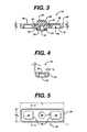
Fig. 3 is an enlarged view of the cover assembly ofFig. 2 . -
Fig. 4 is a cross-section of the cover, taken along line 4-4 ofFig. 5 . -
Fig. 5 is a top view of the cover. -
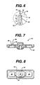
Fig. 6 is an enlarged view ofarea 6 inFig. 2 , withoutinsulator 32. -
Fig. 7 illustrates a second embodiment, with a plugged fill hole through a raised portion of the cover. -
Fig. 8 is a top view of the cover assembly shown in cross-section inFig. 3 . - Referring to
Figs. 1 and 2 , an F6prismatic cell 10 has a housing assembly including a deep drawn, nickel plated CRS can 12 and acover assembly 14. The internal components of the cell are not shown, but are typical of standard F6 cells, and include at least two electrodes.Cover assembly 14 includes a stamped nickel platedCRS cover 16, aplastic vent seal 18, ametal rivet 20, awasher 22, avent plug 24 and a metal contact (pip) 26. During assembly,cover 16 is pressed down into theopen end 28 of can 12 and welded about the entire length of its periphery alongseam 30 to seal the cover to the can. Anouter insulator 32 of heat-shrinkable material is placed over the housing after assembly. - Referring to
Figs. 3 and 4 ,cover 16 has a nominal thickness tc of about 0.33 millimeter, and, as stamped to an overall height Hc of 1.62 millimeters, has aperipheral lip 34 that extends toward one broad side of the cover.Lip 34 has a lip height HL of about 1.3 millimeters. Also stamped into the cover are two raisedbumps 36, one on either side of thehole 38, which is punched through the cover at its center.Hole 38 may be punched through the cover blank from its outer side, prior to forming the lip and bumps. By punching the hole from the outer side of the cover, aridge 40 is formed at its inner side and theouter surface 41 remains flat for sealing. The punching operation further provides a radius at the edge of the hole at the outer side of the cover to assist with the insertion ofseal 18.Rivet 20 is inserted through the seal,washer 22 is set in place, and the smaller, inner flange of the rivet is formed to hold the rivet, seal and washer in place.Vent plug 24 andpip 26 are set in place and the pip is spot welded to the larger, outer flange ofrivet 20. As assembled, seal 18 and washer 22 electrically insulate the rivet and pip from the cover, as the cover is in electrical communication with the cell anode and the pip is in electrical communication with the cell cathode.Lip 34 is tapered outward at an angle θ of about 2.5 degrees, providing secure engagement with the inner surfaces of the housing can, as discussed below with respect toFig. 6 . - As shown in
Fig. 5 , thesides 42 of raisedbumps 36 facing ventassembly mounting hole 38 are arcuate, having a radius, R, of about 2.2 millimeters. Thesecurved sides 42 restrain the oval vent assembly (rivet 20 and everything in contact with it) from rotating inhole 38 after assembly of the seal and pip to the cover, as shown inFig. 8 . In addition to preventing rotation of the seal and vent, bumps 36 form cavities 44 (Fig. 4 ) on the inner side of the cover, which provide additional internal cell volume.Bumps 36 andlip 34 also increase the bending stiffness of the cover, which has finished overall dimensions Wc and Lc of about 5.0 and 15.8 millimeters, respectively, slightly larger than the corresponding dimensions between opposing sides of the can at its open end. The four corners ofcover 16 have an outer radius, r, of about 0.75 millimeter to match a similar inner radius at the corners of the opening of the can. - Referring to
Fig. 6 , outwardly taperedlip 34 ofcover 16 is elastically deflected inwardly as the cover is pressed into the open end ofcan 12, while the sides of the can are deflected outwardly. These elastic deflections provide a contact load between the can and cover to ensure a tight fit atseam 30, even with relatively high dimensional tolerances. For instance, can 12 can be drawn with a 0.25 degree side draft angle and an opening tolerance of +/- 0.004 inch (0.1 millimeter) in each dimension while maintaining reliable press fits. Pressed into place, the cover contacts the inner surface ofcan 12 along a length Xc of about 0.6 millimeter (preferably, about three times the heavier wall thickness of the two adjoining walls). After the cover is pressed into the can until the edge oflip 34 is flush with the edge ofcan 12 as shown, the cover and can are welded together by a laser directed atseam 30 in the direction of arrow A, producing a melt zone shown by dashed line B and sealing the seam. The laser beam travels along the length of seam 30 (either the cell or the laser may be physically moved) to complete the weld. - Referring to
Fig. 7 , a second embodiment 14' of the cover assembly has a cover 16' with a pluggedfill hole 46 in one of the raised bumps 36. The fill hole is employed to pressure test and fill the cell with electrolyte after welding cover assembly 14' to the can, and is subsequently plugged with a stainless steel ball 48 (e.g., of about 1.6 millimeters in diameter) which is welded in place by laser or TIG welding.
Claims (15)
- A prismatic battery having an electrically conductive housing comprising:a prismatic can having an open end defined between extending, opposing sides of the can; anda housing cover disposed between and sealed against the opposing sides at the open end of the can, the can and cover together enclosing a volume, the cover having an outer flange about its periphery, the flange when disposed between the opposing sides of the can extending in the direction of extension of the sides of the can and defining therewith a welded seam, characterized in that the cover flange is tapered outward to provide pressure between the flange and the sides of the housing can, and in that the housing cover is a Mectangules cover with Madiused corners.
- A prismatic battery according to claim 1, wherein the cover has a raised portion defining therein a pocket in hydraulic communication with the enclosed volume.
- A prismatic battery according to claims 1 or 2, wherein the prismatic can has a minimum dimension between opposing sides at the open end of less than about 6.0 millimeters.
- A prismatic battery according to any one of the preceding claims, wherein the cover is of stamped metal.
- A prismatic battery according to any one of the preceding claims, wherein the cover defines a hole therethrough, the battery further comprising:an external electrical contact attached to the cover at the hole; anda seal disposed between the contact and the cover to electrically insulate the contact from the cover.
- A prismatic battery according to claim 5, wherein the raised portion is arranged to engage the seal to prevent the rotation of the seal with respect to the cover.
- A prismatic battery according to claim 6, comprising two said raised portions, the seal disposed between and constrained against rotation by the two raised portions.
- A prismatic battery according to any one of claims 2 to 7, wherein the raised portion defines therethrough a fill hole, the battery further comprising a plug disposed within and sealing the fill hole,
- A prismatic battery according to claim 8, wherein the plug comprises a metal ball.
- A prismatic battery according to any one of the preceding claims, wherein the height of the flange in the direction of extent of the sides of the can is at least three times the nominal thickness of the cover.
- A method of constructing a battery with an electrically conductive prismatic battery housing, the method comprising:pressing a housing cover into the open end of an elongated, prismatic can to enclose a volume, the open end being defined between extending, opposing sides of the can, the cover having an outer flange about its periphery, the flange when pressed into the can extending in the direction of extension of the sides of the can and defining therewith a seam, the cover having a raised portion defining therein a pocket in hydraulic communication with the enclosed volume; andwelding the seam to seal the cover to the can, characterized in that the flange is tapered outward to provide pressure between the flange and the sides of the housing can and in that the housing cover is a rectangular cover with Mediased corners.
- A method according to claim 11, wherein the step of welding comprises directing a laser beam at the seam in the direction of extent of the sides of the can.
- A method according to claims 11 or 12, wherein the steps of pressing includes resiliently deflecting the sides of the can outward at the open end of the can.
- A method according to any one of claims 11 to 13, wherein the raised portion defines therethrough a fill hole, the method further comprising, after welding,
adding electrolyte to the enclosed volume through the fill hole; and
plugging the fill hole to seal the enclosed volume. - A method according to claim 14, further comprising, before plugging, applying an elevated test pressure to the enclosed volume through the fill hole.
Applications Claiming Priority (3)
| Application Number | Priority Date | Filing Date | Title |
|---|---|---|---|
| US09/038,326 US6001504A (en) | 1998-03-11 | 1998-03-11 | Prismatic battery housing |
| US38326 | 1998-03-11 | ||
| PCT/US1999/004781 WO1999046825A1 (en) | 1998-03-11 | 1999-03-04 | Prismatic battery housing |
Publications (3)
| Publication Number | Publication Date |
|---|---|
| EP1062704A1 EP1062704A1 (en) | 2000-12-27 |
| EP1062704A4 EP1062704A4 (en) | 2004-08-04 |
| EP1062704B1 true EP1062704B1 (en) | 2008-08-20 |
Family
ID=21899309
Family Applications (1)
| Application Number | Title | Priority Date | Filing Date |
|---|---|---|---|
| EP99911113A Expired - Lifetime EP1062704B1 (en) | 1998-03-11 | 1999-03-04 | Prismatic battery housing |
Country Status (11)
| Country | Link |
|---|---|
| US (1) | US6001504A (en) |
| EP (1) | EP1062704B1 (en) |
| JP (1) | JP2002507047A (en) |
| KR (1) | KR20010041724A (en) |
| CN (1) | CN1292935A (en) |
| AT (1) | ATE405955T1 (en) |
| AU (1) | AU2983399A (en) |
| CA (1) | CA2322897A1 (en) |
| DE (1) | DE69939372D1 (en) |
| TW (1) | TW416162B (en) |
| WO (1) | WO1999046825A1 (en) |
Cited By (1)
| Publication number | Priority date | Publication date | Assignee | Title |
|---|---|---|---|---|
| EP4546959A1 (en) * | 2023-10-24 | 2025-04-30 | MAHLE International GmbH | Cover and housing with cover |
Families Citing this family (28)
| Publication number | Priority date | Publication date | Assignee | Title |
|---|---|---|---|---|
| JP3604879B2 (en) * | 1997-08-05 | 2004-12-22 | 松下電器産業株式会社 | Battery manufacturing method |
| MY122324A (en) * | 1998-02-03 | 2006-04-29 | Toyo Kohan Co Ltd | A method of forming a protection film for a safety valve element, a safety valve element which is coated with a protection film, a closing plate for battery using same and a closed battery using same. |
| JP2000090893A (en) * | 1998-09-17 | 2000-03-31 | Japan Storage Battery Co Ltd | Battery and method for manufacturing battery |
| JP2000133211A (en) * | 1998-10-27 | 2000-05-12 | Matsushita Electric Ind Co Ltd | Manufacturing method for prismatic batteries |
| AU5878800A (en) * | 1999-06-18 | 2001-01-09 | Leupold & Stevens Inc. | Replaceable battery module |
| US7070881B2 (en) * | 2001-10-18 | 2006-07-04 | Quallion Llc | Electrical battery assembly and method of manufacture |
| JP2003142146A (en) * | 2001-10-31 | 2003-05-16 | Japan Storage Battery Co Ltd | Battery |
| US6780539B2 (en) * | 2002-02-21 | 2004-08-24 | The Gillette Company | Alkaline battery with flat housing |
| CN100405155C (en) | 2003-12-19 | 2008-07-23 | 鸿富锦精密工业(深圳)有限公司 | Backlight module |
| KR20060102751A (en) * | 2005-03-24 | 2006-09-28 | 삼성에스디아이 주식회사 | Lithium secondary battery |
| US7645538B1 (en) | 2005-08-22 | 2010-01-12 | Greatbatch Ltd. | Fill plug for electrochemical cell |
| US20070148533A1 (en) * | 2005-12-23 | 2007-06-28 | Anglin David L | Batteries |
| US7527893B2 (en) * | 2006-05-23 | 2009-05-05 | Microsoft Corporation | Eliminating incorrect battery installation |
| KR100934459B1 (en) * | 2006-11-27 | 2009-12-30 | 주식회사 엘지화학 | Battery pack with excellent productivity and structural stability |
| US9478785B2 (en) * | 2007-04-27 | 2016-10-25 | Microsoft Technology Licensing, Llc | Polarity protection for multiple batteries |
| WO2009061451A1 (en) * | 2007-11-07 | 2009-05-14 | Enerdel, Inc. | Battery assembly with temperature control device |
| CN101904042B (en) * | 2007-12-05 | 2014-11-05 | 埃纳德尔公司 | Battery pack with temperature control |
| US8597825B2 (en) * | 2008-05-10 | 2013-12-03 | Enerdel, Inc. | Battery assembly including battery module with wrap blanket between module and encapsulating solution |
| US8334067B2 (en) | 2009-01-13 | 2012-12-18 | The Gillette Company | Non-uniform conductive coating for cathode active material |
| CN102280598B (en) * | 2011-01-27 | 2014-03-12 | 丁振荣 | Lithium battery block, manufacturing method and lithium battery |
| CN104094450B (en) * | 2012-02-22 | 2016-11-16 | 日立汽车系统株式会社 | Square secondary battery |
| US9985265B2 (en) * | 2015-04-13 | 2018-05-29 | Johnson Controls Technology Company | Flexible ribs of a bus bar carrier |
| US10396343B2 (en) | 2015-05-05 | 2019-08-27 | Cps Technology Holdings Llc | Sealing patch for electrolyte fill hole |
| DE102016116842B3 (en) * | 2016-09-08 | 2018-02-15 | Lisa Dräxlmaier GmbH | Connector for electrically connecting two electrical assemblies |
| CN207818650U (en) * | 2018-01-31 | 2018-09-04 | 宁德时代新能源科技股份有限公司 | Top cover and secondary battery |
| KR20220118834A (en) * | 2021-02-19 | 2022-08-26 | 삼성에스디아이 주식회사 | Rechargeable battery |
| JP7523664B2 (en) * | 2021-09-30 | 2024-07-26 | 寧徳時代新能源科技股▲分▼有限公司 | Battery cell, its manufacturing method and manufacturing system, battery, and power consumption device |
| US20260011831A1 (en) * | 2022-10-27 | 2026-01-08 | Lg Energy Solution, Ltd. | Welding Structure of Battery Can and Cap, and Battery Cell Having the Same Applied Thereto |
Family Cites Families (41)
| Publication number | Priority date | Publication date | Assignee | Title |
|---|---|---|---|---|
| US3524770A (en) * | 1966-07-11 | 1970-08-18 | Servel Inc | Dry cell seal |
| BE759896R (en) * | 1969-05-01 | 1971-05-17 | Leclanche Sa | ANTI-MAGNETIC ALKALINE ELEMENT |
| US3841913A (en) * | 1972-12-15 | 1974-10-15 | Esb Inc | Unitary cathode cover |
| DE2324254A1 (en) * | 1973-05-14 | 1974-11-28 | Varta Batterie | GALVANIC PRIMARY CELL |
| US3977907A (en) * | 1975-11-28 | 1976-08-31 | The Gates Rubber Company | Rechargeable battery enclosure |
| IL50095A0 (en) * | 1976-07-21 | 1976-09-30 | Tadiran Il Electronics Ind Ltd | Sealed primary cells |
| DE2918376A1 (en) * | 1978-05-11 | 1979-11-15 | Gte Sylvania Inc | CONTAINER FOR AN ELECTROCHEMICAL ELEMENT |
| US4216277A (en) * | 1979-06-21 | 1980-08-05 | The Gates Rubber Company | Vibration resistant electrochemical cell |
| DE2941757C2 (en) * | 1979-10-16 | 1982-06-16 | Varta Batterie Ag, 3000 Hannover | Closure arrangement for galvanic elements and process for their production |
| DE3003763A1 (en) * | 1980-02-01 | 1981-08-06 | Rudolf 7896 Wutöschingen Klaschka | METAL LID WITH ELECTRICALLY INSULATED ELECTRICAL BUSHING |
| JPS5774964A (en) * | 1980-10-27 | 1982-05-11 | Sanyo Electric Co Ltd | Method of sealing battery |
| US4374909A (en) * | 1981-06-26 | 1983-02-22 | Union Carbide Corporation | Seals for electrochemical cells |
| JPS58158857A (en) * | 1982-03-16 | 1983-09-21 | Hitachi Maxell Ltd | Manufacturing method for sealed type battery |
| CA1179730A (en) * | 1982-06-16 | 1984-12-18 | Marian Wiacek | Snap-in sealing and insulating member for galvanic cells |
| US4476202A (en) * | 1982-06-23 | 1984-10-09 | Union Carbide Corporation | Two-piece cover-seal construction for galvanic cells |
| US5080984A (en) * | 1983-06-17 | 1992-01-14 | Gates Energy Products, Inc. | Radial seal for an electrochemical cell and method of making same |
| US4523376A (en) * | 1983-06-17 | 1985-06-18 | General Electric Company | Method for sealing a rechargable cell |
| US4537841A (en) * | 1983-11-04 | 1985-08-27 | Duracell Inc. | Metal-supported seals for galvanic cells |
| DE3425170A1 (en) * | 1984-07-09 | 1986-01-16 | Varta Batterie Ag, 3000 Hannover | GALVANIC PRIME ELEMENT |
| US4700468A (en) * | 1986-06-26 | 1987-10-20 | Vsesojuzny Nauchnoissledovatelsky Proektno-Konstruktorsky I Tekhnologichesky Akkumulyatorny Institut | Method of assembling a cylindrical storage battery |
| US4822377A (en) * | 1988-02-18 | 1989-04-18 | Energy Conversion Devices, Inc. | Method for sealing an electrochemical cell employing an improved reinforced cover assembly |
| US4999264A (en) * | 1989-11-24 | 1991-03-12 | Duracell Inc. | Aqueous electrochemical cell |
| US5080985A (en) * | 1989-12-07 | 1992-01-14 | Duracell Inc. | High pressure seal for alkaline cells |
| US5079108A (en) * | 1989-12-20 | 1992-01-07 | Rayovac Corporation | Dry cell seal closure |
| US5051323A (en) * | 1990-04-13 | 1991-09-24 | Eveready Battery Company, Inc. | Rollback inner cover |
| US5114808A (en) * | 1990-05-07 | 1992-05-19 | Eveready Battery Company, Inc. | Cell cover with internal compression ring of high yield strength material |
| US5041345A (en) * | 1990-06-08 | 1991-08-20 | Eveready Battery Company | Secondary seal for vented electrochemical cells |
| US5150602A (en) * | 1990-09-10 | 1992-09-29 | Duracell Inc. | Crimping method for electrochemical cells |
| JP2543325Y2 (en) * | 1991-01-14 | 1997-08-06 | ソニー株式会社 | Battery |
| US5248568A (en) * | 1991-10-29 | 1993-09-28 | Eveready Battery Company, Inc. | Blowout multilayer film seal assembly for galvanic cells |
| US5372897A (en) * | 1992-07-24 | 1994-12-13 | Toshiba Battery Co., Ltd. | Rectangular nickel-metal hydride secondary cell |
| US5422201A (en) * | 1993-08-04 | 1995-06-06 | Eveready Battery Company, Inc. | Current collector assembly for an electrochemical cell |
| US5547781A (en) * | 1994-03-02 | 1996-08-20 | Micron Communications, Inc. | Button-type battery with improved separator and gasket construction |
| US5486431A (en) * | 1994-03-02 | 1996-01-23 | Micron Communications, Inc. | Method of producing button-type batteries and spring-biased concave button-type battery |
| US5549717A (en) * | 1994-03-03 | 1996-08-27 | Wilson Greatbatch Ltd. | Method of making prismatic cell |
| US5494495A (en) * | 1994-10-11 | 1996-02-27 | Micron Communications, Inc. | Method of forming button-type batteries |
| DE69529476T2 (en) * | 1994-12-01 | 2003-11-27 | Micron Technology, Inc. | METHOD FOR PRODUCING BUTTON BATTERIES, BUTTON BATTERY INSULATION AND SEALING RING |
| US5658356A (en) * | 1995-05-05 | 1997-08-19 | Rayovac Corporation | Metal-air cathode can having reduced corner radius and electrochemical cells made therewith |
| JP3561554B2 (en) * | 1995-05-31 | 2004-09-02 | 三洋電機株式会社 | battery |
| US5725967A (en) * | 1995-08-15 | 1998-03-10 | Micron Communications, Inc. | Battery container and method of manufacture |
| JP3016065B2 (en) * | 1995-11-10 | 2000-03-06 | 古河電池株式会社 | Manufacturing method of cylindrical nickel-hydrogen secondary battery |
-
1998
- 1998-03-11 US US09/038,326 patent/US6001504A/en not_active Expired - Lifetime
-
1999
- 1999-03-04 CA CA002322897A patent/CA2322897A1/en not_active Abandoned
- 1999-03-04 JP JP2000536110A patent/JP2002507047A/en active Pending
- 1999-03-04 WO PCT/US1999/004781 patent/WO1999046825A1/en not_active Ceased
- 1999-03-04 KR KR1020007009956A patent/KR20010041724A/en not_active Withdrawn
- 1999-03-04 EP EP99911113A patent/EP1062704B1/en not_active Expired - Lifetime
- 1999-03-04 AU AU29833/99A patent/AU2983399A/en not_active Abandoned
- 1999-03-04 DE DE69939372T patent/DE69939372D1/en not_active Expired - Lifetime
- 1999-03-04 CN CN99803889XA patent/CN1292935A/en active Pending
- 1999-03-04 AT AT99911113T patent/ATE405955T1/en not_active IP Right Cessation
- 1999-04-06 TW TW088103662A patent/TW416162B/en not_active IP Right Cessation
Cited By (2)
| Publication number | Priority date | Publication date | Assignee | Title |
|---|---|---|---|---|
| EP4546959A1 (en) * | 2023-10-24 | 2025-04-30 | MAHLE International GmbH | Cover and housing with cover |
| WO2025087631A1 (en) * | 2023-10-24 | 2025-05-01 | Mahle International Gmbh | Cover and housing with cover |
Also Published As
| Publication number | Publication date |
|---|---|
| WO1999046825A1 (en) | 1999-09-16 |
| EP1062704A1 (en) | 2000-12-27 |
| US6001504A (en) | 1999-12-14 |
| ATE405955T1 (en) | 2008-09-15 |
| AU2983399A (en) | 1999-09-27 |
| CN1292935A (en) | 2001-04-25 |
| TW416162B (en) | 2000-12-21 |
| EP1062704A4 (en) | 2004-08-04 |
| KR20010041724A (en) | 2001-05-25 |
| DE69939372D1 (en) | 2008-10-02 |
| CA2322897A1 (en) | 1999-09-16 |
| JP2002507047A (en) | 2002-03-05 |
Similar Documents
| Publication | Publication Date | Title |
|---|---|---|
| EP1062704B1 (en) | Prismatic battery housing | |
| JP4493623B2 (en) | Secondary battery | |
| KR100449763B1 (en) | Cap assembly and secondary battery applying the same | |
| KR102601042B1 (en) | Cylindrical secondary battery | |
| EP2157633B1 (en) | Secondary battery | |
| EP2515362B1 (en) | Secondary battery | |
| US20160155998A1 (en) | Secondary battery | |
| EP3082178B1 (en) | Rechargeable battery | |
| KR20000076885A (en) | Sealed battery suited to production in a slim rectangular form | |
| US6207319B1 (en) | Cap assembly for secondary battery | |
| JP2008311193A (en) | Battery and manufacturing method thereof | |
| KR102824566B1 (en) | Cylindrical secondary battery | |
| US6235424B1 (en) | Cap assembly for secondary battery and method for assembling the same | |
| KR102661207B1 (en) | Secondary Battery | |
| CN118202513A (en) | Cylindrical secondary battery and method for manufacturing the same | |
| MXPA00008833A (en) | Prismatic battery housing | |
| KR20210056066A (en) | Secondary battery | |
| CN222914963U (en) | Battery and electronic device | |
| JP2002279944A (en) | Sealed battery | |
| JPH11339737A (en) | Prismatic battery | |
| CN221551955U (en) | Cylindrical cells and battery packs | |
| JP2006134625A (en) | Sealed battery | |
| KR20260059306A (en) | Secondary battery and method for manufacturing same | |
| KR20260020707A (en) | Secondary battery and method for manufacturing the same | |
| KR20010047791A (en) | Prismatic type Secondary Battery |
Legal Events
| Date | Code | Title | Description |
|---|---|---|---|
| PUAI | Public reference made under article 153(3) epc to a published international application that has entered the european phase |
Free format text: ORIGINAL CODE: 0009012 |
|
| 17P | Request for examination filed |
Effective date: 20001005 |
|
| AK | Designated contracting states |
Kind code of ref document: A1 Designated state(s): AT BE CH DE DK ES FI FR GB GR IE IT LI LU NL PT SE |
|
| A4 | Supplementary search report drawn up and despatched |
Effective date: 20040623 |
|
| 17Q | First examination report despatched |
Effective date: 20060131 |
|
| 17Q | First examination report despatched |
Effective date: 20060131 |
|
| REG | Reference to a national code |
Ref country code: HK Ref legal event code: WD Ref document number: 1033202 Country of ref document: HK |
|
| GRAP | Despatch of communication of intention to grant a patent |
Free format text: ORIGINAL CODE: EPIDOSNIGR1 |
|
| RAP1 | Party data changed (applicant data changed or rights of an application transferred) |
Owner name: THE GILLETTE COMPANY |
|
| GRAS | Grant fee paid |
Free format text: ORIGINAL CODE: EPIDOSNIGR3 |
|
| GRAA | (expected) grant |
Free format text: ORIGINAL CODE: 0009210 |
|
| AK | Designated contracting states |
Kind code of ref document: B1 Designated state(s): AT BE CH DE DK ES FI FR GB GR IE IT LI LU NL PT SE |
|
| REG | Reference to a national code |
Ref country code: GB Ref legal event code: FG4D |
|
| REG | Reference to a national code |
Ref country code: CH Ref legal event code: EP |
|
| REG | Reference to a national code |
Ref country code: IE Ref legal event code: FG4D |
|
| REF | Corresponds to: |
Ref document number: 69939372 Country of ref document: DE Date of ref document: 20081002 Kind code of ref document: P |
|
| PG25 | Lapsed in a contracting state [announced via postgrant information from national office to epo] |
Ref country code: NL Free format text: LAPSE BECAUSE OF FAILURE TO SUBMIT A TRANSLATION OF THE DESCRIPTION OR TO PAY THE FEE WITHIN THE PRESCRIBED TIME-LIMIT Effective date: 20080820 Ref country code: ES Free format text: LAPSE BECAUSE OF FAILURE TO SUBMIT A TRANSLATION OF THE DESCRIPTION OR TO PAY THE FEE WITHIN THE PRESCRIBED TIME-LIMIT Effective date: 20081201 |
|
| PG25 | Lapsed in a contracting state [announced via postgrant information from national office to epo] |
Ref country code: FI Free format text: LAPSE BECAUSE OF FAILURE TO SUBMIT A TRANSLATION OF THE DESCRIPTION OR TO PAY THE FEE WITHIN THE PRESCRIBED TIME-LIMIT Effective date: 20080820 Ref country code: AT Free format text: LAPSE BECAUSE OF FAILURE TO SUBMIT A TRANSLATION OF THE DESCRIPTION OR TO PAY THE FEE WITHIN THE PRESCRIBED TIME-LIMIT Effective date: 20080820 |
|
| PG25 | Lapsed in a contracting state [announced via postgrant information from national office to epo] |
Ref country code: DK Free format text: LAPSE BECAUSE OF FAILURE TO SUBMIT A TRANSLATION OF THE DESCRIPTION OR TO PAY THE FEE WITHIN THE PRESCRIBED TIME-LIMIT Effective date: 20080820 |
|
| PG25 | Lapsed in a contracting state [announced via postgrant information from national office to epo] |
Ref country code: PT Free format text: LAPSE BECAUSE OF FAILURE TO SUBMIT A TRANSLATION OF THE DESCRIPTION OR TO PAY THE FEE WITHIN THE PRESCRIBED TIME-LIMIT Effective date: 20090120 |
|
| PLBE | No opposition filed within time limit |
Free format text: ORIGINAL CODE: 0009261 |
|
| STAA | Information on the status of an ep patent application or granted ep patent |
Free format text: STATUS: NO OPPOSITION FILED WITHIN TIME LIMIT |
|
| 26N | No opposition filed |
Effective date: 20090525 |
|
| PG25 | Lapsed in a contracting state [announced via postgrant information from national office to epo] |
Ref country code: IT Free format text: LAPSE BECAUSE OF FAILURE TO SUBMIT A TRANSLATION OF THE DESCRIPTION OR TO PAY THE FEE WITHIN THE PRESCRIBED TIME-LIMIT Effective date: 20080820 |
|
| REG | Reference to a national code |
Ref country code: CH Ref legal event code: PL |
|
| PG25 | Lapsed in a contracting state [announced via postgrant information from national office to epo] |
Ref country code: SE Free format text: LAPSE BECAUSE OF FAILURE TO SUBMIT A TRANSLATION OF THE DESCRIPTION OR TO PAY THE FEE WITHIN THE PRESCRIBED TIME-LIMIT Effective date: 20081120 Ref country code: LI Free format text: LAPSE BECAUSE OF NON-PAYMENT OF DUE FEES Effective date: 20090331 Ref country code: IE Free format text: LAPSE BECAUSE OF NON-PAYMENT OF DUE FEES Effective date: 20090304 Ref country code: CH Free format text: LAPSE BECAUSE OF NON-PAYMENT OF DUE FEES Effective date: 20090331 |
|
| PGFP | Annual fee paid to national office [announced via postgrant information from national office to epo] |
Ref country code: FR Payment date: 20100318 Year of fee payment: 12 |
|
| PGFP | Annual fee paid to national office [announced via postgrant information from national office to epo] |
Ref country code: GB Payment date: 20100208 Year of fee payment: 12 |
|
| PGFP | Annual fee paid to national office [announced via postgrant information from national office to epo] |
Ref country code: DE Payment date: 20100331 Year of fee payment: 12 |
|
| PG25 | Lapsed in a contracting state [announced via postgrant information from national office to epo] |
Ref country code: GR Free format text: LAPSE BECAUSE OF FAILURE TO SUBMIT A TRANSLATION OF THE DESCRIPTION OR TO PAY THE FEE WITHIN THE PRESCRIBED TIME-LIMIT Effective date: 20081121 |
|
| PGFP | Annual fee paid to national office [announced via postgrant information from national office to epo] |
Ref country code: BE Payment date: 20100504 Year of fee payment: 12 |
|
| PG25 | Lapsed in a contracting state [announced via postgrant information from national office to epo] |
Ref country code: LU Free format text: LAPSE BECAUSE OF NON-PAYMENT OF DUE FEES Effective date: 20090304 |
|
| BERE | Be: lapsed |
Owner name: THE GILLETTE CY Effective date: 20110331 |
|
| GBPC | Gb: european patent ceased through non-payment of renewal fee |
Effective date: 20110304 |
|
| REG | Reference to a national code |
Ref country code: FR Ref legal event code: ST Effective date: 20111130 |
|
| PG25 | Lapsed in a contracting state [announced via postgrant information from national office to epo] |
Ref country code: BE Free format text: LAPSE BECAUSE OF NON-PAYMENT OF DUE FEES Effective date: 20110331 |
|
| PG25 | Lapsed in a contracting state [announced via postgrant information from national office to epo] |
Ref country code: DE Free format text: LAPSE BECAUSE OF NON-PAYMENT OF DUE FEES Effective date: 20111001 Ref country code: FR Free format text: LAPSE BECAUSE OF NON-PAYMENT OF DUE FEES Effective date: 20110331 |
|
| REG | Reference to a national code |
Ref country code: DE Ref legal event code: R119 Ref document number: 69939372 Country of ref document: DE Effective date: 20111001 |
|
| PG25 | Lapsed in a contracting state [announced via postgrant information from national office to epo] |
Ref country code: GB Free format text: LAPSE BECAUSE OF NON-PAYMENT OF DUE FEES Effective date: 20110304 |