EP1062702B1 - Piezoelectric transformer - Google Patents
Piezoelectric transformer Download PDFInfo
- Publication number
- EP1062702B1 EP1062702B1 EP99906081A EP99906081A EP1062702B1 EP 1062702 B1 EP1062702 B1 EP 1062702B1 EP 99906081 A EP99906081 A EP 99906081A EP 99906081 A EP99906081 A EP 99906081A EP 1062702 B1 EP1062702 B1 EP 1062702B1
- Authority
- EP
- European Patent Office
- Prior art keywords
- piezoelectric
- primary
- piezoelectric transformer
- annular body
- transformer
- Prior art date
- Legal status (The legal status is an assumption and is not a legal conclusion. Google has not performed a legal analysis and makes no representation as to the accuracy of the status listed.)
- Expired - Lifetime
Links
Images


Classifications
-
- H—ELECTRICITY
- H10—SEMICONDUCTOR DEVICES; ELECTRIC SOLID-STATE DEVICES NOT OTHERWISE PROVIDED FOR
- H10N—ELECTRIC SOLID-STATE DEVICES NOT OTHERWISE PROVIDED FOR
- H10N30/00—Piezoelectric or electrostrictive devices
- H10N30/40—Piezoelectric or electrostrictive devices with electrical input and electrical output, e.g. functioning as transformers
Definitions
- the invention relates to a piezoelectric transformer comprising a piezoelectric body which is divided into a primary portion and a secondary portion, whereby both the primary portion and the secondary portion are able to generate and transform piezoelectric vibrations in accordance with an AC-voltage fed to one portion while a transformed voltage can be delivered from the other portion.
- a known piezoelectric transformer of this type comprises a piezoelectric body in form of an oblong plate having a mechanical resonance frequency.
- the transformer is preferably operated at this resonance frequency.
- this transformer is encumbered with the draw-back that further resonance frequencies may have an effect on the mode of operation of the transformer.
- US-PS No. 3,736,446 discloses an annular transformer.
- the piezoelectric material is layered by means of through electrodes along a portion of the periphery of this transformer, said portion utilizing oscillations in the peripheral direction.
- a ring can be painted on the ceramics.
- This structure is encumbered with the draw-back that it is relatively expensive to manufacture.
- the resonance frequency is relatively low for oscillation types along the periphery.
- the transformable effect is proportional to the frequency. The effect transformable by means of this annular transformer is therefore relatively insignificant.
- JP-A-09-321363 describes a columnar shape without a through-going opening in the longitudinal direction. It works in the longitudinal mode. As a result the resonance frequency is very low and the power density will be low also.
- the object of the invention is therefore to provide a piezoelectric transformer presenting a higher field intensity than hitherto known and which does not involve undesired resonance frequencies.
- a piezoelectric transformer of the above type is according to the invention characterised in that the piezoelectric body is formed by a substantially oval or annular body which has been polarised substantially perpendicular to the peripheral direction.
- An annular piezoelectric body presents three basic modes of vibration, viz. the periphery presenting the lowest frequency and a planar and a thickness vibration presenting a comparatively higher frequency due to the reduced extent of the vital dimension. Therefore the annular transformer is according to the invention able to operate at a comparatively higher frequency as it operates on a thickness vibration instead of a peripheral vibration.
- the geometry provides an increased capacity, which together with the increased operation frequency results in a reduced output impedance.
- the transformer is able to handle increased currents, typically in the range of 0.1 to 5 A.
- the power in the transformer is transferred as a mechanical vibration.
- the maximum allowed, transferred power depends on the fatigue strength of the ceramics.
- the maximum allowable strain and e vol is constant.
- the resonance frequencies are higher for the thickness vibration than for the peripheral vibration, and as far as conventional piezoelectric ceramics of the power type is concerned, the associated coupling coefficients are 0.3 to 0.35 (k 31 , peripheral vibration) and 0.40 to 0.45 (k T , thickness vibration), respectively.
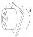
- the piezoelectric transformer illustrated in Fig. 1 comprises an annular piezoelectric body on each side of an insulating plate 1.
- One piezoelectric body 2 serves as primary portion whereas the other piezoelectric body 3 serves as secondary portion. Electrodes are provided both at the primary portion 2 and at the secondary portion 3, and both said primary portion and said secondary portion are able to generate and transform piezoelectric vibrations in response to an AC-voltage fed from one portion while the transformed voltage can be delivered from the other portion.
- each piezoelectric body is formed by a substantially oval or annular body.
- a vital factor for maximizing the efficient coupling is that b/h is either less than 0.25 or 0.35 ⁇ b/h ⁇ 0.8 or especially 0.4 ⁇ b/h ⁇ 0.7, where b represents the width and h represents the height.
- Fig. 2 illustrates that the transformer operates as a semiwave resonator.
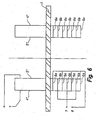
- Fig. 3 illustrates an example of an electrode structure at both the primary portion and at the secondary portion.
- a circumferential electrode is provided on the primary portion both at the top side 4 and at the bottom side 5.
- the secondary portion is formed as a multilayer structure with inner electrodes 69, 66. These inner electrodes 69, 66 are alternately connected to one output terminal 7 and the other output terminal 8.
- one primary electrode 5' has been moved away from the insulating layer 1 so as to reduce the mechanical stresses during the polarisation. Unlike the insulating layer 1, the ceramics is subjected to dimensional changes during the polarisation.
- Fig. 5 illustrates an alternative positioning of the primary electrodes on the inner side and the outer side, respectively, of the annular body 2.
- the secondary electrodes 6 a , 6 b are positioned in the same position as in Figs. 3 and 4 .
- Fig. 6 illustrates an alternative positioning of the primary electrodes, where the inner electrode has been withdrawn so as to reduce the polarisation stresses.
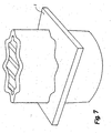
- Fig 7 illustrates an alternative embodiment of the piezoelectric body.
- the piezoelectric material is preferably a PZT ceramics. PZT is preferred because it presents an increased dielectricity constant and an increased coupling coefficient.
- the transformer can for instance be used for transforming 120 VAC into 12 VAC.
- the piezoelectric transformer presents a relatively high energy density, viz. up to 0.04 W/cm 3 kHz corresponding to a field intensity of 20 W/cm 3 at 500 kHz.
- the component is suited for miniaturising.
- the insulation between the primary and the secondary portions depends no longer on the leakage path along the surface of the transformer, but on the breakdown voltage in the insulating layer. Therefore the reduced dimensions present no hindrance to meet the same or higher requirements to the insulation.
- the operating frequency is typically 500 kHz.
- the piezoelectric material can be Navy type 1.
- the external diameter is 10 mm, whereas the internal diameter is 7 mm.
- Each part is of a length of 1.8 mm, and the two parts are separated by a round aluminium disk of a thickness of 0.25 mm.
- the total length of the transformer is 3.85 mm.
- transformers have been discussed until now where one part is a multilayer component while the other part is a bulk component. It is, however, also possible that both components are either bulk or multilayer components in response to the desired voltage ratio and the impedance conditions to which the transformer is to be adapted.
- the bulk components are less expensive and it is possible to obtain a voltage ratio of up to 1:3 by employing materials presenting a varying permittivity on the primary and the secondary portions.
Abstract
Description
- The invention relates to a piezoelectric transformer comprising a piezoelectric body which is divided into a primary portion and a secondary portion, whereby both the primary portion and the secondary portion are able to generate and transform piezoelectric vibrations in accordance with an AC-voltage fed to one portion while a transformed voltage can be delivered from the other portion.
- A known piezoelectric transformer of this type comprises a piezoelectric body in form of an oblong plate having a mechanical resonance frequency. The transformer is preferably operated at this resonance frequency. However, this transformer is encumbered with the draw-back that further resonance frequencies may have an effect on the mode of operation of the transformer.
- Furthermore,
US-PS No. 3,736,446 discloses an annular transformer. The piezoelectric material is layered by means of through electrodes along a portion of the periphery of this transformer, said portion utilizing oscillations in the peripheral direction. As an alternative, a ring can be painted on the ceramics. This structure is encumbered with the draw-back that it is relatively expensive to manufacture. In addition, the resonance frequency is relatively low for oscillation types along the periphery. The transformable effect is proportional to the frequency. The effect transformable by means of this annular transformer is therefore relatively insignificant. -
JP-A-09-321363 - The object of the invention is therefore to provide a piezoelectric transformer presenting a higher field intensity than hitherto known and which does not involve undesired resonance frequencies.
- A piezoelectric transformer of the above type is according to the invention characterised in that the piezoelectric body is formed by a substantially oval or annular body which has been polarised substantially perpendicular to the peripheral direction. An annular piezoelectric body presents three basic modes of vibration, viz. the periphery presenting the lowest frequency and a planar and a thickness vibration presenting a comparatively higher frequency due to the reduced extent of the vital dimension. Therefore the annular transformer is according to the invention able to operate at a comparatively higher frequency as it operates on a thickness vibration instead of a peripheral vibration. Moreover, the geometry provides an increased capacity, which together with the increased operation frequency results in a reduced output impedance. Thus the transformer is able to handle increased currents, typically in the range of 0.1 to 5 A.
- The power in the transformer is transferred as a mechanical vibration. The maximum allowed, transferred power depends on the fatigue strength of the ceramics. For a predetermined maximum mechanical strain in the ceramics the transferred power is

where - P =
- transferred power
- fres =
- resonance frequency
- vol =
- volume
- keff =
- efficient piezoelectric coupling coefficient corresponding to the exist- ing mode of vibration
- ε =
- dielectric permittivity
- When two annular transformers are made of the same ceramics and with the same volume, the maximum allowable strain and e vol is constant. As previously mentioned, the resonance frequencies are higher for the thickness vibration than for the peripheral vibration, and as far as conventional piezoelectric ceramics of the power type is concerned, the associated coupling coefficients are 0.3 to 0.35 (k31, peripheral vibration) and 0.40 to 0.45 (kT, thickness vibration), respectively.
- The difference in coupling coefficient results in an increased power density of

and the resonance frequency is typically a factor 10 higher. Totally, the power density is increased by 1.65·10 = 16.5. - The invention is explained in greater detail below with reference to the accompanying drawings, in which
-
Fig. 1 illustrates a piezoelectric transformer with an annular piezoelectric body on each side of an insulating plate, -
Fig. 2 is a sectional view through the transformer ofFig. 1 and illustrating the vibrations, -
Fig. 3 is a sectional view through the transformer ofFig. 1 and illustrating the electrode configurations, -
Fig. 4 is a sectional view corresponding to the sectional view ofFig. 3 . where one primary electrode has been moved away from the insulating layer so as to reduce the mechanical stresses due to the polarisation, -
Fig. 5 is a sectional view corresponding to the sectional view ofFig. 3 , but showing an alternative positioning of the primary electrodes, -
Fig. 6 is a sectional view corresponding to the sectional view ofFig. 5 , where the inner electrode has been withdrawn so as to reduce the polarisation stresses, -
Fig. 7 illustrates an alternative embodiment of a piezoelectric transformer, where the annular piezoelectric body presents a wavy closed shape, and -
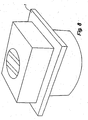
Fig. 8 illustrates an alternative embodiment of a piezoelectric transformer, where the primary portion is quadrangular and presents a circular opening. - The piezoelectric transformer illustrated in
Fig. 1 comprises an annular piezoelectric body on each side of an insulating plate 1. One piezoelectric body 2 serves as primary portion whereas the other piezoelectric body 3 serves as secondary portion. Electrodes are provided both at the primary portion 2 and at the secondary portion 3, and both said primary portion and said secondary portion are able to generate and transform piezoelectric vibrations in response to an AC-voltage fed from one portion while the transformed voltage can be delivered from the other portion. According to the invention each piezoelectric body is formed by a substantially oval or annular body. As a result, an improved uniform distribution of the stresses, an increased coupling coefficient as well as improved cooling conditions are obtained. A vital factor for maximizing the efficient coupling is that b/h is either less than 0.25 or 0.35 < b/h < 0.8 or especially 0.4 < b/h < 0.7, where b represents the width and h represents the height. -
Fig. 2 illustrates that the transformer operates as a semiwave resonator.. -
Fig. 3 illustrates an example of an electrode structure at both the primary portion and at the secondary portion. A circumferential electrode is provided on the primary portion both at thetop side 4 and at thebottom side 5. The secondary portion is formed as a multilayer structure with inner electrodes 69, 66. These inner electrodes 69, 66 are alternately connected to oneoutput terminal 7 and theother output terminal 8. - In
Fig. 4 , one primary electrode 5' has been moved away from the insulating layer 1 so as to reduce the mechanical stresses during the polarisation. Unlike the insulating layer 1, the ceramics is subjected to dimensional changes during the polarisation. -
Fig. 5 illustrates an alternative positioning of the primary electrodes on the inner side and the outer side, respectively, of the annular body 2. Thesecondary electrodes 6a, 6b are positioned in the same position as inFigs. 3 and4 . -
Fig. 6 illustrates an alternative positioning of the primary electrodes, where the inner electrode has been withdrawn so as to reduce the polarisation stresses. -
Fig 7 illustrates an alternative embodiment of the piezoelectric body. The piezoelectric material is preferably a PZT ceramics. PZT is preferred because it presents an increased dielectricity constant and an increased coupling coefficient. - The transformer can for instance be used for transforming 120 VAC into 12 VAC. The piezoelectric transformer presents a relatively high energy density, viz. up to 0.04 W/cm3 kHz corresponding to a field intensity of 20 W/cm3 at 500 kHz. Thus the component is suited for miniaturising.
- Other things being equal, the latter results in a comparatively smaller component, which in turn involves a reduced cost price. The increased operating frequency has also the effect that filter components (coils, capacitors) of the associated structure can present lower values and consequently a reduced physical size as well as a reduced price.
- The insulation between the primary and the secondary portions depends no longer on the leakage path along the surface of the transformer, but on the breakdown voltage in the insulating layer. Therefore the reduced dimensions present no hindrance to meet the same or higher requirements to the insulation.
- The operating frequency is typically 500 kHz. The piezoelectric material can be Navy type 1. The external diameter is 10 mm, whereas the internal diameter is 7 mm. Each part is of a length of 1.8 mm, and the two parts are separated by a round aluminium disk of a thickness of 0.25 mm. The total length of the transformer is 3.85 mm.
- Nothing but transformers have been discussed until now where one part is a multilayer component while the other part is a bulk component. It is, however, also possible that both components are either bulk or multilayer components in response to the desired voltage ratio and the impedance conditions to which the transformer is to be adapted. The bulk components are less expensive and it is possible to obtain a voltage ratio of up to 1:3 by employing materials presenting a varying permittivity on the primary and the secondary portions.
- Furthermore it is possible to use an either triangular or quadrangular blank with a round opening instead of the cylindrical blank, of.
Fig. 8 . The opening is asymmetrically positioned so as to further attenuate undesired resonances. Quadrangles can be cut out in a cost-saving manner, and it is easy to drill round openings.
Claims (9)
- Piezoelectric transformer comprising a substantially piezoelectric body which is divided into a primary portion (2) and a secondary portion (3), both the primary portion and the secondary portion being able to generate and transform piezoelectric vibrations in accordance with an AC-voltage fed to one portion while a transformed voltage can be delivered from the other portion, characterised in that the piezoelectric body is constituted by a substantially annular body, which has been polarised substantially perpendicular to a peripheral direction of the annular body.
- A piezoelectric transformer according to claim 1, wherein the substantially annular body is an annular body.
- A piezoelectric transformer according to claim 1, wherein the annular piezoelectric body has been polarized in the longitudinal direction.
- A piezoelectric transformer as claimed in claim 1, wherein the primary portion of the annular piezoelectric body has been substantially radially polarised.
- A piezoelectric transformer according to claim 1 for 2, wherein the transformer is operated at a thickness resonance frequency.
- A piezoelectric transformer according to claim 1 or 2, wherein the ratio b/h between the width b of the wall of the annular body and the height h of the wall of the annular body is either at the most 0.25 or in the range between 0.35 and 0.8.
- A piezoelectric transformer according to claim 6, wherein the ratio b/h is between 0.4 and 0.7.
- A piezoelectric transformer according to any of the preceding claims, wherein a portion of the piezoelectric transformer is a multilayer structure.
- A piezoelectric transformer according to any of the preceding claims, wherein the piezoelectric material is a PZT ceramic.
Applications Claiming Priority (3)
| Application Number | Priority Date | Filing Date | Title |
|---|---|---|---|
| DK28498 | 1998-03-03 | ||
| DK199800284A DK176073B1 (en) | 1998-03-03 | 1998-03-03 | Piezoelectric transformer |
| PCT/DK1999/000096 WO1999045600A2 (en) | 1998-03-03 | 1999-03-02 | Piezoelectric transformer |
Publications (2)
| Publication Number | Publication Date |
|---|---|
| EP1062702A2 EP1062702A2 (en) | 2000-12-27 |
| EP1062702B1 true EP1062702B1 (en) | 2010-05-19 |
Family
ID=8091833
Family Applications (1)
| Application Number | Title | Priority Date | Filing Date |
|---|---|---|---|
| EP99906081A Expired - Lifetime EP1062702B1 (en) | 1998-03-03 | 1999-03-02 | Piezoelectric transformer |
Country Status (8)
| Country | Link |
|---|---|
| US (1) | US6707235B1 (en) |
| EP (1) | EP1062702B1 (en) |
| JP (1) | JP4392989B2 (en) |
| AT (1) | ATE468617T1 (en) |
| AU (1) | AU2611199A (en) |
| DE (1) | DE69942388D1 (en) |
| DK (1) | DK176073B1 (en) |
| WO (1) | WO1999045600A2 (en) |
Cited By (1)
| Publication number | Priority date | Publication date | Assignee | Title |
|---|---|---|---|---|
| DE102015119656A1 (en) | 2015-11-13 | 2017-05-18 | Epcos Ag | Piezoelectric transformer |
Families Citing this family (15)
| Publication number | Priority date | Publication date | Assignee | Title |
|---|---|---|---|---|
| US20040215243A1 (en) * | 2003-04-25 | 2004-10-28 | Houben Richard P.M. | Implantable medical device with piezoelectric transformer |
| US7203551B2 (en) * | 2003-04-25 | 2007-04-10 | Medtronic, Inc. | Implantable lead-based sensor powered by piezoelectric transformer |
| FR2877145B1 (en) * | 2004-10-21 | 2006-12-29 | Inst Nat Sciences Appliq | COMPOSITE PIEZOELECTRIC TRANSFORMER WITH VERY HIGH INSULATION AND VERY LOW COUPLING BETWEEN SECONDARY AND PRIMARY |
| JP2006156774A (en) * | 2004-11-30 | 2006-06-15 | Nec Tokin Corp | Piezoelectric transformer |
| DE102004058743A1 (en) * | 2004-12-06 | 2006-06-14 | Epcos Ag | Piezoelectric transformer and method for its production |
| US7183698B1 (en) | 2005-08-29 | 2007-02-27 | Zippy Technology Corp. | Piezoelectric structure |
| DE102006044186A1 (en) * | 2006-09-20 | 2008-03-27 | Epcos Ag | Transformer arrangement with a piezotransformer |
| US7492078B1 (en) | 2007-09-19 | 2009-02-17 | Zippy Technology Corp. | Circular piezoelectric apparatus |
| DE102008016364A1 (en) * | 2008-03-29 | 2009-10-01 | Biotronik Crm Patent Ag | Signal line of an implantable electromedical device |
| EP2251700A1 (en) | 2009-05-12 | 2010-11-17 | Kamstrup A/S | Magnetically immune consumption meter |
| WO2012020034A1 (en) | 2010-08-09 | 2012-02-16 | Pi-Harvest Holding Ag | Medical system, piezoelectric kit, related methods and medical procedures |
| US9842983B2 (en) | 2010-10-07 | 2017-12-12 | Epcos Ag | Piezoelectric multi-layer component |
| KR102560807B1 (en) * | 2016-05-30 | 2023-07-28 | 주식회사 위츠 | Resonance apparatus and apparatus for transmitting power wirelessly using the same |
| JP6770590B2 (en) | 2016-06-14 | 2020-10-14 | コーニンクレッカ フィリップス エヌ ヴェKoninklijke Philips N.V. | Actuator device and drive method incorporating an electroactive polymer actuator |
| US11911831B2 (en) | 2019-05-29 | 2024-02-27 | Big Kaiser Prazisionswerkzeuge Ag | Boring head with a mechanism for clamping a displaceable tool carrier |
Family Cites Families (28)
| Publication number | Priority date | Publication date | Assignee | Title |
|---|---|---|---|---|
| US3736446A (en) | 1968-06-04 | 1973-05-29 | Vernitron Corp | Piezoelectric transformer |
| US3562563A (en) * | 1969-03-26 | 1971-02-09 | Motorola Inc | Circumferentially slotted tubular piezoelectric transformer |
| US3781955A (en) * | 1970-12-21 | 1974-01-01 | V Lavrinenko | Method of making a piezoelectric element |
| DE2650356A1 (en) * | 1976-11-03 | 1978-05-11 | Battelle Institut E V | Piezoelectric ultrasonic transducer generating tubular waves - consists of piezoelectric tube and annular, comb shaped electrodes |
| FR2409654B1 (en) * | 1977-11-17 | 1985-10-04 | Thomson Csf | PIEZOELECTRIC TRANSDUCER DEVICE AND MANUFACTURING METHOD THEREOF |
| FR2477822A1 (en) * | 1980-03-04 | 1981-09-11 | Thomson Csf | ACTIVE SUSPENSION ELECTROMECHANICAL TRANSDUCER AND METHOD FOR MANUFACTURING THE SAME |
| US4525645A (en) * | 1983-10-11 | 1985-06-25 | Southwest Research Institute | Cylindrical bender-type vibration transducer |
| JPS61139112A (en) * | 1984-12-10 | 1986-06-26 | Murata Mfg Co Ltd | Layer-built piezoelectric element capable of frequency adjustment |
| US5045744A (en) * | 1988-12-23 | 1991-09-03 | Murata Mfg. Co. | Energy-trapping-by-frequency-lowering-type piezoelectric-resonance device |
| US5118982A (en) | 1989-05-31 | 1992-06-02 | Nec Corporation | Thickness mode vibration piezoelectric transformer |
| US5081391A (en) * | 1989-09-13 | 1992-01-14 | Southwest Research Institute | Piezoelectric cylindrical transducer for producing or detecting asymmetrical vibrations |
| JP3064458B2 (en) * | 1991-04-02 | 2000-07-12 | 日本電気株式会社 | Thickness longitudinal vibration piezoelectric transformer and its driving method |
| AU1597895A (en) * | 1994-01-06 | 1995-08-01 | Cardiometrics, Inc. | Ultrasonic transducer with selectable beamwidth and method |
| JP3039307B2 (en) * | 1995-02-15 | 2000-05-08 | 日本電気株式会社 | Piezoelectric transformer and method of manufacturing the same |
| DE69722691T2 (en) | 1996-02-14 | 2003-12-18 | Murata Manufacturing Co | Piezoelectric transformer |
| JP3090023B2 (en) | 1996-02-14 | 2000-09-18 | 株式会社村田製作所 | Multilayer piezoelectric transformer |
| JP3090022B2 (en) | 1996-02-14 | 2000-09-18 | 株式会社村田製作所 | Multilayer piezoelectric transformer |
| US5852229A (en) * | 1996-05-29 | 1998-12-22 | Kimberly-Clark Worldwide, Inc. | Piezoelectric resonator chemical sensing device |
| JP2885183B2 (en) * | 1996-05-30 | 1999-04-19 | 日本電気株式会社 | Piezoelectric transformer and its supporting structure |
| US5814922A (en) * | 1997-11-18 | 1998-09-29 | The Penn State Research Foundation | Annular piezoelectric transformer |
| US6201874B1 (en) * | 1998-12-07 | 2001-03-13 | American Technology Corporation | Electrostatic transducer with nonplanar configured diaphragm |
| US6400065B1 (en) * | 1998-03-31 | 2002-06-04 | Measurement Specialties, Inc. | Omni-directional ultrasonic transducer apparatus and staking method |
| JP2000138554A (en) * | 1998-11-02 | 2000-05-16 | Murata Mfg Co Ltd | Energy confinement piezoelectric resonator |
| US6362559B1 (en) * | 1999-02-12 | 2002-03-26 | Face International Corp. | Piezoelectric transformer with segmented electrodes |
| US6426585B1 (en) * | 1999-12-08 | 2002-07-30 | Kazuo Kohno | Thickness or length polarized piezoelectric transformer |
| KR20010102673A (en) * | 2000-05-04 | 2001-11-16 | 이형도 | Piezoelectric ceramic material with large power output ability and transformer made of it |
| KR100363791B1 (en) * | 2000-05-04 | 2002-12-11 | 삼성전기주식회사 | Piezoelectric ceramic material with large power output ability and transformer made of it |
| US6411014B1 (en) * | 2000-05-09 | 2002-06-25 | Measurement Specialties, Inc. | Cylindrical transducer apparatus |
-
1998
- 1998-03-03 DK DK199800284A patent/DK176073B1/en not_active IP Right Cessation
-
1999
- 1999-03-02 AT AT99906081T patent/ATE468617T1/en not_active IP Right Cessation
- 1999-03-02 AU AU26111/99A patent/AU2611199A/en not_active Abandoned
- 1999-03-02 DE DE69942388T patent/DE69942388D1/en not_active Expired - Lifetime
- 1999-03-02 EP EP99906081A patent/EP1062702B1/en not_active Expired - Lifetime
- 1999-03-02 WO PCT/DK1999/000096 patent/WO1999045600A2/en active Application Filing
- 1999-03-02 JP JP2000535056A patent/JP4392989B2/en not_active Expired - Fee Related
-
2000
- 2000-09-11 US US09/659,490 patent/US6707235B1/en not_active Expired - Lifetime
Cited By (2)
| Publication number | Priority date | Publication date | Assignee | Title |
|---|---|---|---|---|
| DE102015119656A1 (en) | 2015-11-13 | 2017-05-18 | Epcos Ag | Piezoelectric transformer |
| US11101426B2 (en) | 2015-11-13 | 2021-08-24 | Epcos Ag | Piezoelectric transformer |
Also Published As
| Publication number | Publication date |
|---|---|
| ATE468617T1 (en) | 2010-06-15 |
| DK28498A (en) | 1999-09-04 |
| DE69942388D1 (en) | 2010-07-01 |
| EP1062702A2 (en) | 2000-12-27 |
| US6707235B1 (en) | 2004-03-16 |
| JP4392989B2 (en) | 2010-01-06 |
| DK176073B1 (en) | 2006-04-03 |
| WO1999045600A2 (en) | 1999-09-10 |
| AU2611199A (en) | 1999-09-20 |
| JP2002506291A (en) | 2002-02-26 |
| WO1999045600A3 (en) | 1999-10-21 |
Similar Documents
| Publication | Publication Date | Title |
|---|---|---|
| EP1062702B1 (en) | Piezoelectric transformer | |
| US6366006B1 (en) | Composite piezoelectric transformer | |
| US5814922A (en) | Annular piezoelectric transformer | |
| EP1148522B1 (en) | Low noise and low loss reactor | |
| US6051915A (en) | Piezoelectric transformer | |
| CA2244765C (en) | Piezoelectric transformer | |
| US6215227B1 (en) | Thickness mode piezoelectric transformer with end-masses | |
| US7075217B2 (en) | Laminated piezoelectric transformer | |
| US5675208A (en) | Lithium niobate piezoelectric transformer operating in thickness-shear mode | |
| US5070486A (en) | Process to increase the power of the low frequency electro acoustic transducers and corresponding transducers | |
| US6140747A (en) | Piezoelectric transformer element and method of manufacturing the same | |
| CN116213232A (en) | Ultrasonic torsional vibration device | |
| EP3381042B1 (en) | Rf transmitter and method of manufacture thereof | |
| JPH05160633A (en) | Composite micro strip antenna | |
| EP1553615B1 (en) | Magnetron | |
| Saveliev et al. | Resonance magnetoelectric effect in a composite ferromagnet–dielectric–piezoelectric Langevin-type resonator | |
| JP2003532317A (en) | Electroacoustic transducer | |
| KR100388264B1 (en) | High efficiency piezo electric transformer by using multisector and parallel poling direction method within one-body | |
| SU1099338A1 (en) | Dielectric vibrator | |
| US7872549B2 (en) | Quasi-lumped resonator apparatus and method | |
| RU2298299C1 (en) | Ultrasound magnetostrictive transformer | |
| JPH11150311A (en) | Piezoelectric transformer | |
| JPS633219Y2 (en) | ||
| US20050077983A1 (en) | Device for filtering signals in the K band including a dielectric resonator made from a material that is not temperature-compensated | |
| Vazquez Carazo | Laminated piezoelectric transformer |
Legal Events
| Date | Code | Title | Description |
|---|---|---|---|
| PUAI | Public reference made under article 153(3) epc to a published international application that has entered the european phase |
Free format text: ORIGINAL CODE: 0009012 |
|
| 17P | Request for examination filed |
Effective date: 20001004 |
|
| AK | Designated contracting states |
Kind code of ref document: A2 Designated state(s): AT BE CH DE DK ES FI FR GB GR IE IT LI NL SE |
|
| 17Q | First examination report despatched |
Effective date: 20070917 |
|
| GRAP | Despatch of communication of intention to grant a patent |
Free format text: ORIGINAL CODE: EPIDOSNIGR1 |
|
| RAP1 | Party data changed (applicant data changed or rights of an application transferred) |
Owner name: NOLIAC A/S |
|
| GRAS | Grant fee paid |
Free format text: ORIGINAL CODE: EPIDOSNIGR3 |
|
| GRAA | (expected) grant |
Free format text: ORIGINAL CODE: 0009210 |
|
| AK | Designated contracting states |
Kind code of ref document: B1 Designated state(s): AT BE CH DE DK ES FI FR GB GR IE IT LI NL SE |
|
| REG | Reference to a national code |
Ref country code: GB Ref legal event code: FG4D |
|
| REG | Reference to a national code |
Ref country code: CH Ref legal event code: EP |
|
| REG | Reference to a national code |
Ref country code: IE Ref legal event code: FG4D |
|
| REF | Corresponds to: |
Ref document number: 69942388 Country of ref document: DE Date of ref document: 20100701 Kind code of ref document: P |
|
| REG | Reference to a national code |
Ref country code: NL Ref legal event code: T3 |
|
| PG25 | Lapsed in a contracting state [announced via postgrant information from national office to epo] |
Ref country code: SE Free format text: LAPSE BECAUSE OF FAILURE TO SUBMIT A TRANSLATION OF THE DESCRIPTION OR TO PAY THE FEE WITHIN THE PRESCRIBED TIME-LIMIT Effective date: 20100519 Ref country code: ES Free format text: LAPSE BECAUSE OF FAILURE TO SUBMIT A TRANSLATION OF THE DESCRIPTION OR TO PAY THE FEE WITHIN THE PRESCRIBED TIME-LIMIT Effective date: 20100830 |
|
| PG25 | Lapsed in a contracting state [announced via postgrant information from national office to epo] |
Ref country code: FI Free format text: LAPSE BECAUSE OF FAILURE TO SUBMIT A TRANSLATION OF THE DESCRIPTION OR TO PAY THE FEE WITHIN THE PRESCRIBED TIME-LIMIT Effective date: 20100519 Ref country code: AT Free format text: LAPSE BECAUSE OF FAILURE TO SUBMIT A TRANSLATION OF THE DESCRIPTION OR TO PAY THE FEE WITHIN THE PRESCRIBED TIME-LIMIT Effective date: 20100519 |
|
| PG25 | Lapsed in a contracting state [announced via postgrant information from national office to epo] |
Ref country code: DK Free format text: LAPSE BECAUSE OF FAILURE TO SUBMIT A TRANSLATION OF THE DESCRIPTION OR TO PAY THE FEE WITHIN THE PRESCRIBED TIME-LIMIT Effective date: 20100519 |
|
| PG25 | Lapsed in a contracting state [announced via postgrant information from national office to epo] |
Ref country code: BE Free format text: LAPSE BECAUSE OF FAILURE TO SUBMIT A TRANSLATION OF THE DESCRIPTION OR TO PAY THE FEE WITHIN THE PRESCRIBED TIME-LIMIT Effective date: 20100519 |
|
| PLBE | No opposition filed within time limit |
Free format text: ORIGINAL CODE: 0009261 |
|
| STAA | Information on the status of an ep patent application or granted ep patent |
Free format text: STATUS: NO OPPOSITION FILED WITHIN TIME LIMIT |
|
| 26N | No opposition filed |
Effective date: 20110222 |
|
| PG25 | Lapsed in a contracting state [announced via postgrant information from national office to epo] |
Ref country code: GR Free format text: LAPSE BECAUSE OF FAILURE TO SUBMIT A TRANSLATION OF THE DESCRIPTION OR TO PAY THE FEE WITHIN THE PRESCRIBED TIME-LIMIT Effective date: 20100820 |
|
| PGFP | Annual fee paid to national office [announced via postgrant information from national office to epo] |
Ref country code: NL Payment date: 20110329 Year of fee payment: 13 |
|
| REG | Reference to a national code |
Ref country code: DE Ref legal event code: R097 Ref document number: 69942388 Country of ref document: DE Effective date: 20110221 |
|
| PGFP | Annual fee paid to national office [announced via postgrant information from national office to epo] |
Ref country code: IT Payment date: 20110328 Year of fee payment: 13 |
|
| REG | Reference to a national code |
Ref country code: CH Ref legal event code: PL |
|
| REG | Reference to a national code |
Ref country code: IE Ref legal event code: MM4A |
|
| PG25 | Lapsed in a contracting state [announced via postgrant information from national office to epo] |
Ref country code: IE Free format text: LAPSE BECAUSE OF NON-PAYMENT OF DUE FEES Effective date: 20110302 Ref country code: LI Free format text: LAPSE BECAUSE OF NON-PAYMENT OF DUE FEES Effective date: 20110331 Ref country code: CH Free format text: LAPSE BECAUSE OF NON-PAYMENT OF DUE FEES Effective date: 20110331 |
|
| REG | Reference to a national code |
Ref country code: NL Ref legal event code: V1 Effective date: 20121001 |
|
| PG25 | Lapsed in a contracting state [announced via postgrant information from national office to epo] |
Ref country code: IT Free format text: LAPSE BECAUSE OF NON-PAYMENT OF DUE FEES Effective date: 20120302 |
|
| PG25 | Lapsed in a contracting state [announced via postgrant information from national office to epo] |
Ref country code: NL Free format text: LAPSE BECAUSE OF NON-PAYMENT OF DUE FEES Effective date: 20121001 |
|
| REG | Reference to a national code |
Ref country code: GB Ref legal event code: 732E Free format text: REGISTERED BETWEEN 20150416 AND 20150422 |
|
| REG | Reference to a national code |
Ref country code: DE Ref legal event code: R081 Ref document number: 69942388 Country of ref document: DE Owner name: LIMIEL ESPANA SL, ES Free format text: FORMER OWNER: NOLIAC A/S, KVISTGAARD, DK Effective date: 20150422 |
|
| REG | Reference to a national code |
Ref country code: FR Ref legal event code: TP Owner name: LIMIEL ESPANA S.L., ES Effective date: 20150717 |
|
| REG | Reference to a national code |
Ref country code: FR Ref legal event code: PLFP Year of fee payment: 17 |
|
| PGFP | Annual fee paid to national office [announced via postgrant information from national office to epo] |
Ref country code: GB Payment date: 20150916 Year of fee payment: 17 |
|
| PGFP | Annual fee paid to national office [announced via postgrant information from national office to epo] |
Ref country code: FR Payment date: 20150930 Year of fee payment: 17 |
|
| PGFP | Annual fee paid to national office [announced via postgrant information from national office to epo] |
Ref country code: DE Payment date: 20160920 Year of fee payment: 18 |
|
| GBPC | Gb: european patent ceased through non-payment of renewal fee |
Effective date: 20160302 |
|
| REG | Reference to a national code |
Ref country code: FR Ref legal event code: ST Effective date: 20161130 |
|
| PG25 | Lapsed in a contracting state [announced via postgrant information from national office to epo] |
Ref country code: FR Free format text: LAPSE BECAUSE OF NON-PAYMENT OF DUE FEES Effective date: 20160331 Ref country code: GB Free format text: LAPSE BECAUSE OF NON-PAYMENT OF DUE FEES Effective date: 20160302 |
|
| REG | Reference to a national code |
Ref country code: DE Ref legal event code: R119 Ref document number: 69942388 Country of ref document: DE |
|
| PG25 | Lapsed in a contracting state [announced via postgrant information from national office to epo] |
Ref country code: DE Free format text: LAPSE BECAUSE OF NON-PAYMENT OF DUE FEES Effective date: 20171003 |