EP1061609A2 - Terminal fitting - Google Patents
Terminal fitting Download PDFInfo
- Publication number
- EP1061609A2 EP1061609A2 EP00304035A EP00304035A EP1061609A2 EP 1061609 A2 EP1061609 A2 EP 1061609A2 EP 00304035 A EP00304035 A EP 00304035A EP 00304035 A EP00304035 A EP 00304035A EP 1061609 A2 EP1061609 A2 EP 1061609A2
- Authority
- EP
- European Patent Office
- Prior art keywords
- retainer
- terminal
- posterior
- terminal fitting
- anterior
- Prior art date
- Legal status (The legal status is an assumption and is not a legal conclusion. Google has not performed a legal analysis and makes no representation as to the accuracy of the status listed.)
- Granted
Links
Images



Classifications
-
- H—ELECTRICITY
- H01—ELECTRIC ELEMENTS
- H01R—ELECTRICALLY-CONDUCTIVE CONNECTIONS; STRUCTURAL ASSOCIATIONS OF A PLURALITY OF MUTUALLY-INSULATED ELECTRICAL CONNECTING ELEMENTS; COUPLING DEVICES; CURRENT COLLECTORS
- H01R13/00—Details of coupling devices of the kinds covered by groups H01R12/70 or H01R24/00 - H01R33/00
- H01R13/40—Securing contact members in or to a base or case; Insulating of contact members
- H01R13/42—Securing in a demountable manner
- H01R13/436—Securing a plurality of contact members by one locking piece or operation
- H01R13/4367—Insertion of locking piece from the rear
-
- H—ELECTRICITY
- H01—ELECTRIC ELEMENTS
- H01R—ELECTRICALLY-CONDUCTIVE CONNECTIONS; STRUCTURAL ASSOCIATIONS OF A PLURALITY OF MUTUALLY-INSULATED ELECTRICAL CONNECTING ELEMENTS; COUPLING DEVICES; CURRENT COLLECTORS
- H01R13/00—Details of coupling devices of the kinds covered by groups H01R12/70 or H01R24/00 - H01R33/00
- H01R13/40—Securing contact members in or to a base or case; Insulating of contact members
- H01R13/42—Securing in a demountable manner
- H01R13/422—Securing in resilient one-piece base or case, e.g. by friction; One-piece base or case formed with resilient locking means
- H01R13/4223—Securing in resilient one-piece base or case, e.g. by friction; One-piece base or case formed with resilient locking means comprising integral flexible contact retaining fingers
Definitions
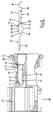
- Figure 11 of this specification shows an example of a terminal fitting which is inserted within a connector housing provided with a retainer.
- This terminal fitting 1 consists of a box-shaped main body 2 provided at the anterior, and attaching members 3 for crimping electric wires provided at the posterior.
- the terminal fitting 1 When the terminal fitting 1 is in an inserted state within a cavity 5 of a connector housing 4, it is retained by a lance 5A which protrudes from an upper face of the cavity 5, and is doubly retained by a retainer 6 which is inserted from a lower face side of the cavity 5.
- the retainer 6 is provided with a stopping member 6A which is capable of engaging with a posterior side face 2A of the main body 2 of the terminal fitting 1.
- Such a terminal has an upstanding projection adapted to prevent insertion of the retainer before the retainer has been inserted a significant distance. Accordingly the retainer protrudes to a greater degree compared with the prior art, and half-fitting is more likely to be noticed.
- the retainer is preferably insertable at an acute angle to the direction of insertion of the terminal, and may have temporary and final positions determined by a releasable resilient latch thereof.
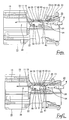
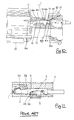
- a male terminal fitting 30 is described first. As shown in Figure 3, this male terminal fitting 30 is inserted into a connector housing 10 provided with a retainer 20 which is inserted diagonally from a posterior direction.
- the retainer 20 is maintained in the housing 10 by a maintaining mechanism (not shown, but for example a resilient latch) and is capable of moving diagonally in an anterior-posterior direction. Stopping members 21 which correspond with each cavity 11 protrude diagonally towards the anterior from an inner face of each retainer 20, these stopping members 21 engaging with each terminal fitting 30.
- the retainer 20 When the half-inserted state of the terminal fitting 30 is detected, the retainer 20 is in a more shallowly inserted state than, for example, when the movement of the retainer 20 is prevented by its stopping member 21 striking against the opposing face 39 of the terminal fitting 30.
- the amount of protrusion of the retainer 20 is determined by the height of the detecting protrusion 42. That is, the half-inserted state of the terminal fitting 30 can be detected early due to the height of the detecting protrusion 42.
- the retainer 20 needs to be moved only a little from the temporary stopping position before its movement is halted. There can be no confusion between this and the case where the retainer 20 is pressed into the main stopping position shown in Figure 5 and its movement is halted. Consequently, the half-inserted state of the terminal fitting 30 can be detected readily.
- the second embodiment explains a terminal fitting having a detecting member with a different shape.
Landscapes
- Connector Housings Or Holding Contact Members (AREA)
- Details Of Connecting Devices For Male And Female Coupling (AREA)
Abstract
Description
Claims (15)
- An electrical terminal (30) for insertion into a connector body, the terminal (30) having an anterior end (32) for connection to a mating terminal, a posterior end (33) for connection to an electrical wire, and a mid-portion (31) having a recess (40) adapted to receive a retainer, wherein said terminal (30) further comprises an upstanding projection (42, 42A) at the anterior side of said recess (40), said projection (42, 42A) having an upper side (44, 44A) for contact with a retainer in a half fitted state with said connector body, and a posterior side (43, 43A) for contact with a retainer in a fully fitted state with said connector body.
- A terminal according to claim 1 where said projection comprises a tab (42) part-sheared from said mid-portion (31).
- A terminal according to claim 2 wherein said tab (42) is substantially rectangular in elevation.
- A terminal according to claim 2 or claim 3 wherein said mid-portion (31) is symmetrical, and said tab (42) is on the axial centerline thereof.
- A terminal according to claim 4 and further including a stabiliser (36) anterior to said tab (42), said stabiliser (36) also comprising an upstanding projection part-sheared from said mid-portion (31), and said stabiliser (36) and tab (42) being aligned axially.
- A terminal according to claim 5 wherein said projection (42) presents an 'L' shaped surface to the posterior, for abutment with a retainer in use.
- A terminal according to claim 1 wherein said projection comprises an outward indentation (42A) of said mid-portion (31).
- A terminal according to claim 7 wherein the upper side (44a) of said indentation slopes down towards the anterior.
- A terminal according to claim 8 wherein said indentation (42A) presents an arc-like surface to the posterior, for abutment with a retainer in use.
- A terminal according to any preceding claim and further including an indentation (52) to the posterior of said recess (40), said indentation (52) being adapted to receive a retainer for said terminal.
- A terminal according to claim 10 wherein the posterior side of said indentation is angled towards the posterior end (33).
- A terminal according to any preceding claim wherein said posterior side (43, 43A) is aligned with an anterior edge (41) of said recess (40).
- An electrical connector comprising a body (10) and a terminal (30) according to any preceding claim, said body (10) having a cavity (11), said terminal (30) being insertable into said cavity (11), and said body (10) further including a side opening (16) for said cavity (11) and adapted to receive a retainer (20) for said terminal (30), said retainer (20) being insertable at an acute angle to the direction of insertion of said terminal (30).
- A conenctor according to claim 13 wherein said cavity (11) has a groove (17) in the wall thereof, said groove (17) extending in the direction of insertion of said terminal (30) and being adapted to receive an upstanding stabilising tab (36) of said terminal (30).
- A terminal according to claim 13 or claim 14 wherein said terminal (30) further includes an upstanding projection (42) posterior to said stabilising tab (36), said retainer being adapted to abut the posterior side (43) of said projection (42) thereby to urge said terminal (30) fully into said cavity (11).
Applications Claiming Priority (2)
| Application Number | Priority Date | Filing Date | Title |
|---|---|---|---|
| JP17332699 | 1999-06-18 | ||
| JP17332699A JP3456165B2 (en) | 1999-06-18 | 1999-06-18 | connector |
Publications (3)
| Publication Number | Publication Date |
|---|---|
| EP1061609A2 true EP1061609A2 (en) | 2000-12-20 |
| EP1061609A3 EP1061609A3 (en) | 2003-10-01 |
| EP1061609B1 EP1061609B1 (en) | 2004-11-24 |
Family
ID=15958370
Family Applications (1)
| Application Number | Title | Priority Date | Filing Date |
|---|---|---|---|
| EP00304035A Expired - Lifetime EP1061609B1 (en) | 1999-06-18 | 2000-05-12 | Terminal fitting |
Country Status (4)
| Country | Link |
|---|---|
| US (1) | US6264507B1 (en) |
| EP (1) | EP1061609B1 (en) |
| JP (1) | JP3456165B2 (en) |
| DE (1) | DE60016092T2 (en) |
Cited By (1)
| Publication number | Priority date | Publication date | Assignee | Title |
|---|---|---|---|---|
| EP2494660B1 (en) * | 2009-10-26 | 2020-02-19 | Molex, LLC | Receptacle terminal connector |
Families Citing this family (5)
| Publication number | Priority date | Publication date | Assignee | Title |
|---|---|---|---|---|
| JP2003297490A (en) * | 2002-04-08 | 2003-10-17 | Sumitomo Wiring Syst Ltd | connector |
| JP5104212B2 (en) * | 2007-10-26 | 2012-12-19 | 住友電装株式会社 | connector |
| JP2013038044A (en) * | 2011-08-11 | 2013-02-21 | Sumitomo Wiring Syst Ltd | Connector |
| JP7054452B2 (en) * | 2018-11-02 | 2022-04-14 | 住友電装株式会社 | connector |
| JP7803900B2 (en) * | 2023-06-28 | 2026-01-21 | 矢崎総業株式会社 | connector |
Family Cites Families (8)
| Publication number | Priority date | Publication date | Assignee | Title |
|---|---|---|---|---|
| US3781760A (en) * | 1972-03-28 | 1973-12-25 | Du Pont | Connector block |
| JPS61232578A (en) * | 1985-04-08 | 1986-10-16 | 矢崎総業株式会社 | Housing for electric connector |
| US4690477A (en) * | 1985-04-30 | 1987-09-01 | E. I. Du Pont De Nemours And Company | Electrical connector apparatus |
| JPH0495369A (en) * | 1990-08-01 | 1992-03-27 | Yazaki Corp | Electrical connector with terminal fixture |
| JP2500134B2 (en) * | 1991-03-14 | 1996-05-29 | 矢崎総業株式会社 | Electrical connector |
| JP2901110B2 (en) * | 1992-05-25 | 1999-06-07 | 矢崎総業株式会社 | Electrical connector with rear holder |
| JP2964880B2 (en) * | 1994-08-03 | 1999-10-18 | 住友電装株式会社 | connector |
| JP2852497B2 (en) * | 1995-03-16 | 1999-02-03 | モレックス インコーポレーテッド | Electrical connector |
-
1999
- 1999-06-18 JP JP17332699A patent/JP3456165B2/en not_active Expired - Fee Related
-
2000
- 2000-05-12 EP EP00304035A patent/EP1061609B1/en not_active Expired - Lifetime
- 2000-05-12 DE DE60016092T patent/DE60016092T2/en not_active Expired - Lifetime
- 2000-05-26 US US09/580,924 patent/US6264507B1/en not_active Expired - Lifetime
Cited By (1)
| Publication number | Priority date | Publication date | Assignee | Title |
|---|---|---|---|---|
| EP2494660B1 (en) * | 2009-10-26 | 2020-02-19 | Molex, LLC | Receptacle terminal connector |
Also Published As
| Publication number | Publication date |
|---|---|
| JP3456165B2 (en) | 2003-10-14 |
| EP1061609B1 (en) | 2004-11-24 |
| DE60016092T2 (en) | 2005-11-03 |
| JP2001006789A (en) | 2001-01-12 |
| US6264507B1 (en) | 2001-07-24 |
| EP1061609A3 (en) | 2003-10-01 |
| DE60016092D1 (en) | 2004-12-30 |
Similar Documents
| Publication | Publication Date | Title |
|---|---|---|
| US8678866B2 (en) | Lance of a connector having two contact portions | |
| EP0986143B1 (en) | Connector | |
| EP0867976B1 (en) | Connector | |
| US6461184B2 (en) | Connector | |
| US20080305694A1 (en) | Connector | |
| EP1689034B1 (en) | A terminal fitting, connector provided therewith and method of forming a terminal fitting | |
| US10559908B2 (en) | Connector | |
| EP0677893A2 (en) | Electrical connector with secondary latch | |
| US5562495A (en) | Electric connector | |
| EP1061609B1 (en) | Terminal fitting | |
| US7204728B2 (en) | Terminal fitting and a connector provided therewith | |
| US7033205B2 (en) | Connector with a collision preventing projection | |
| US10826229B2 (en) | Connector with coupling portion | |
| EP0452060A1 (en) | Electrical connector with terminal alignment and position assurance component | |
| US6450840B2 (en) | Connector with insertable retainer | |
| US7001206B2 (en) | Connector and a connector assembly | |
| US11189951B2 (en) | Connector | |
| EP1220365B1 (en) | Divided connector | |
| JPH10247543A (en) | Terminal | |
| JPH11250970A (en) | Connector structure | |
| JP2003243076A (en) | Female terminal fittings and connectors | |
| JPH1197097A (en) | Connector with retainer | |
| JP2000106242A (en) | Electrical connector | |
| JPH1197099A (en) | Connector with retainer | |
| JP2003346618A (en) | connector |
Legal Events
| Date | Code | Title | Description |
|---|---|---|---|
| PUAI | Public reference made under article 153(3) epc to a published international application that has entered the european phase |
Free format text: ORIGINAL CODE: 0009012 |
|
| 17P | Request for examination filed |
Effective date: 20000525 |
|
| AK | Designated contracting states |
Kind code of ref document: A2 Designated state(s): AT BE CH CY DE DK ES FI FR GB GR IE IT LI LU MC NL PT SE |
|
| AX | Request for extension of the european patent |
Free format text: AL;LT;LV;MK;RO;SI |
|
| PUAL | Search report despatched |
Free format text: ORIGINAL CODE: 0009013 |
|
| AK | Designated contracting states |
Kind code of ref document: A3 Designated state(s): AT BE CH CY DE DK ES FI FR GB GR IE IT LI LU MC NL PT SE |
|
| AX | Request for extension of the european patent |
Extension state: AL LT LV MK RO SI |
|
| 17Q | First examination report despatched |
Effective date: 20031215 |
|
| GRAP | Despatch of communication of intention to grant a patent |
Free format text: ORIGINAL CODE: EPIDOSNIGR1 |
|
| AKX | Designation fees paid |
Designated state(s): DE FR GB IT |
|
| GRAS | Grant fee paid |
Free format text: ORIGINAL CODE: EPIDOSNIGR3 |
|
| GRAA | (expected) grant |
Free format text: ORIGINAL CODE: 0009210 |
|
| AK | Designated contracting states |
Kind code of ref document: B1 Designated state(s): DE FR GB IT |
|
| REG | Reference to a national code |
Ref country code: GB Ref legal event code: FG4D |
|
| REF | Corresponds to: |
Ref document number: 60016092 Country of ref document: DE Date of ref document: 20041230 Kind code of ref document: P |
|
| REG | Reference to a national code |
Ref country code: IE Ref legal event code: FG4D |
|
| PG25 | Lapsed in a contracting state [announced via postgrant information from national office to epo] |
Ref country code: GB Free format text: LAPSE BECAUSE OF NON-PAYMENT OF DUE FEES Effective date: 20050512 |
|
| ET | Fr: translation filed | ||
| PLBE | No opposition filed within time limit |
Free format text: ORIGINAL CODE: 0009261 |
|
| STAA | Information on the status of an ep patent application or granted ep patent |
Free format text: STATUS: NO OPPOSITION FILED WITHIN TIME LIMIT |
|
| 26N | No opposition filed |
Effective date: 20050825 |
|
| GBPC | Gb: european patent ceased through non-payment of renewal fee |
Effective date: 20050512 |
|
| REG | Reference to a national code |
Ref country code: FR Ref legal event code: PLFP Year of fee payment: 17 |
|
| PGFP | Annual fee paid to national office [announced via postgrant information from national office to epo] |
Ref country code: DE Payment date: 20160504 Year of fee payment: 17 |
|
| PGFP | Annual fee paid to national office [announced via postgrant information from national office to epo] |
Ref country code: FR Payment date: 20160412 Year of fee payment: 17 Ref country code: IT Payment date: 20160523 Year of fee payment: 17 |
|
| REG | Reference to a national code |
Ref country code: DE Ref legal event code: R119 Ref document number: 60016092 Country of ref document: DE |
|
| REG | Reference to a national code |
Ref country code: FR Ref legal event code: ST Effective date: 20180131 |
|
| PG25 | Lapsed in a contracting state [announced via postgrant information from national office to epo] |
Ref country code: DE Free format text: LAPSE BECAUSE OF NON-PAYMENT OF DUE FEES Effective date: 20171201 |
|
| PG25 | Lapsed in a contracting state [announced via postgrant information from national office to epo] |
Ref country code: IT Free format text: LAPSE BECAUSE OF NON-PAYMENT OF DUE FEES Effective date: 20170512 Ref country code: FR Free format text: LAPSE BECAUSE OF NON-PAYMENT OF DUE FEES Effective date: 20170531 |