EP1061412A1 - Curtain coating apparatus - Google Patents
Curtain coating apparatus Download PDFInfo
- Publication number
- EP1061412A1 EP1061412A1 EP00112609A EP00112609A EP1061412A1 EP 1061412 A1 EP1061412 A1 EP 1061412A1 EP 00112609 A EP00112609 A EP 00112609A EP 00112609 A EP00112609 A EP 00112609A EP 1061412 A1 EP1061412 A1 EP 1061412A1
- Authority
- EP
- European Patent Office
- Prior art keywords
- coating
- regulating plate
- width regulating
- contact angle
- water
- Prior art date
- Legal status (The legal status is an assumption and is not a legal conclusion. Google has not performed a legal analysis and makes no representation as to the accuracy of the status listed.)
- Granted
Links
- 238000007766 curtain coating Methods 0.000 title claims abstract description 24
- 239000011248 coating agent Substances 0.000 claims abstract description 119
- 238000000576 coating method Methods 0.000 claims abstract description 119
- 230000001105 regulatory effect Effects 0.000 claims abstract description 66
- XLYOFNOQVPJJNP-UHFFFAOYSA-N water Substances O XLYOFNOQVPJJNP-UHFFFAOYSA-N 0.000 claims abstract description 42
- 230000008602 contraction Effects 0.000 abstract description 5
- 239000011552 falling film Substances 0.000 abstract description 4
- 239000010408 film Substances 0.000 description 41
- 239000003381 stabilizer Substances 0.000 description 24
- 239000000463 material Substances 0.000 description 20
- 239000010410 layer Substances 0.000 description 19
- 239000002904 solvent Substances 0.000 description 17
- 239000004800 polyvinyl chloride Substances 0.000 description 16
- 239000004810 polytetrafluoroethylene Substances 0.000 description 15
- 229920001343 polytetrafluoroethylene Polymers 0.000 description 15
- 229920000915 polyvinyl chloride Polymers 0.000 description 13
- 230000000052 comparative effect Effects 0.000 description 12
- NIXOWILDQLNWCW-UHFFFAOYSA-N acrylic acid group Chemical group C(C=C)(=O)O NIXOWILDQLNWCW-UHFFFAOYSA-N 0.000 description 8
- 239000000839 emulsion Substances 0.000 description 8
- -1 polyethylene terephthalate Polymers 0.000 description 8
- 108010010803 Gelatin Proteins 0.000 description 7
- 229920000159 gelatin Polymers 0.000 description 7
- 239000008273 gelatin Substances 0.000 description 7
- 235000019322 gelatine Nutrition 0.000 description 7
- 235000011852 gelatine desserts Nutrition 0.000 description 7
- 239000000203 mixture Substances 0.000 description 5
- 101100221809 Neurospora crassa (strain ATCC 24698 / 74-OR23-1A / CBS 708.71 / DSM 1257 / FGSC 987) cpd-7 gene Proteins 0.000 description 4
- 229910001220 stainless steel Inorganic materials 0.000 description 4
- 239000010935 stainless steel Substances 0.000 description 4
- 239000006096 absorbing agent Substances 0.000 description 3
- 238000005452 bending Methods 0.000 description 3
- 229910052751 metal Inorganic materials 0.000 description 3
- 239000002184 metal Substances 0.000 description 3
- 239000002245 particle Substances 0.000 description 3
- 229920003023 plastic Polymers 0.000 description 3
- 239000004033 plastic Substances 0.000 description 3
- 230000003449 preventive effect Effects 0.000 description 3
- ADZWSOLPGZMUMY-UHFFFAOYSA-M silver bromide Chemical compound [Ag]Br ADZWSOLPGZMUMY-UHFFFAOYSA-M 0.000 description 3
- 238000004381 surface treatment Methods 0.000 description 3
- 239000004925 Acrylic resin Substances 0.000 description 2
- 229920000178 Acrylic resin Polymers 0.000 description 2
- SJOOOZPMQAWAOP-UHFFFAOYSA-N [Ag].BrCl Chemical compound [Ag].BrCl SJOOOZPMQAWAOP-UHFFFAOYSA-N 0.000 description 2
- 229910052782 aluminium Inorganic materials 0.000 description 2
- XAGFODPZIPBFFR-UHFFFAOYSA-N aluminium Chemical compound [Al] XAGFODPZIPBFFR-UHFFFAOYSA-N 0.000 description 2
- 230000000694 effects Effects 0.000 description 2
- 239000011521 glass Substances 0.000 description 2
- 230000005764 inhibitory process Effects 0.000 description 2
- 239000007788 liquid Substances 0.000 description 2
- 150000002739 metals Chemical class 0.000 description 2
- 230000002265 prevention Effects 0.000 description 2
- 229910052709 silver Inorganic materials 0.000 description 2
- 239000004332 silver Substances 0.000 description 2
- 239000004698 Polyethylene Substances 0.000 description 1
- 239000004372 Polyvinyl alcohol Substances 0.000 description 1
- BQCADISMDOOEFD-UHFFFAOYSA-N Silver Chemical compound [Ag] BQCADISMDOOEFD-UHFFFAOYSA-N 0.000 description 1
- QVQLCTNNEUAWMS-UHFFFAOYSA-N barium oxide Chemical compound [Ba]=O QVQLCTNNEUAWMS-UHFFFAOYSA-N 0.000 description 1
- 229910001864 baryta Inorganic materials 0.000 description 1
- CODNYICXDISAEA-UHFFFAOYSA-N bromine monochloride Chemical compound BrCl CODNYICXDISAEA-UHFFFAOYSA-N 0.000 description 1
- 239000008199 coating composition Substances 0.000 description 1
- 239000002131 composite material Substances 0.000 description 1
- 238000010276 construction Methods 0.000 description 1
- 238000001035 drying Methods 0.000 description 1
- 229940057995 liquid paraffin Drugs 0.000 description 1
- 238000004519 manufacturing process Methods 0.000 description 1
- 238000007645 offset printing Methods 0.000 description 1
- 229920001467 poly(styrenesulfonates) Polymers 0.000 description 1
- 229920000573 polyethylene Polymers 0.000 description 1
- 229920000139 polyethylene terephthalate Polymers 0.000 description 1
- 239000005020 polyethylene terephthalate Substances 0.000 description 1
- 229920000642 polymer Polymers 0.000 description 1
- 229920002451 polyvinyl alcohol Polymers 0.000 description 1
- 239000011241 protective layer Substances 0.000 description 1
- 238000009877 rendering Methods 0.000 description 1
- 229940006186 sodium polystyrene sulfonate Drugs 0.000 description 1
- 239000000126 substance Substances 0.000 description 1
- 230000008719 thickening Effects 0.000 description 1
Images


Classifications
-
- B—PERFORMING OPERATIONS; TRANSPORTING
- B05—SPRAYING OR ATOMISING IN GENERAL; APPLYING FLUENT MATERIALS TO SURFACES, IN GENERAL
- B05C—APPARATUS FOR APPLYING FLUENT MATERIALS TO SURFACES, IN GENERAL
- B05C5/00—Apparatus in which liquid or other fluent material is projected, poured or allowed to flow on to the surface of the work
- B05C5/007—Slide-hopper coaters, i.e. apparatus in which the liquid or other fluent material flows freely on an inclined surface before contacting the work
- B05C5/008—Slide-hopper curtain coaters
-
- G—PHYSICS
- G03—PHOTOGRAPHY; CINEMATOGRAPHY; ANALOGOUS TECHNIQUES USING WAVES OTHER THAN OPTICAL WAVES; ELECTROGRAPHY; HOLOGRAPHY
- G03C—PHOTOSENSITIVE MATERIALS FOR PHOTOGRAPHIC PURPOSES; PHOTOGRAPHIC PROCESSES, e.g. CINE, X-RAY, COLOUR, STEREO-PHOTOGRAPHIC PROCESSES; AUXILIARY PROCESSES IN PHOTOGRAPHY
- G03C1/00—Photosensitive materials
- G03C1/74—Applying photosensitive compositions to the base; Drying processes therefor
-
- B—PERFORMING OPERATIONS; TRANSPORTING
- B05—SPRAYING OR ATOMISING IN GENERAL; APPLYING FLUENT MATERIALS TO SURFACES, IN GENERAL
- B05C—APPARATUS FOR APPLYING FLUENT MATERIALS TO SURFACES, IN GENERAL
- B05C9/00—Apparatus or plant for applying liquid or other fluent material to surfaces by means not covered by any preceding group, or in which the means of applying the liquid or other fluent material is not important
- B05C9/06—Apparatus or plant for applying liquid or other fluent material to surfaces by means not covered by any preceding group, or in which the means of applying the liquid or other fluent material is not important for applying two different liquids or other fluent materials, or the same liquid or other fluent material twice, to the same side of the work
-
- Y—GENERAL TAGGING OF NEW TECHNOLOGICAL DEVELOPMENTS; GENERAL TAGGING OF CROSS-SECTIONAL TECHNOLOGIES SPANNING OVER SEVERAL SECTIONS OF THE IPC; TECHNICAL SUBJECTS COVERED BY FORMER USPC CROSS-REFERENCE ART COLLECTIONS [XRACs] AND DIGESTS
- Y10—TECHNICAL SUBJECTS COVERED BY FORMER USPC
- Y10S—TECHNICAL SUBJECTS COVERED BY FORMER USPC CROSS-REFERENCE ART COLLECTIONS [XRACs] AND DIGESTS
- Y10S118/00—Coating apparatus
- Y10S118/04—Curtain coater
Definitions
- This invention relates to a curtain coating apparatus which applies various coating composition to a continuously traveling web-shaped support (web) by the curtain coating system, in the production of photographic film, photographic paper, magnetic recording tape, pressure-sensitive recording paper, offset printing plate and the like.
- photographic film is manufactured by applying a coating solution comprising a photographic emulsion to a continuously traveling web made of polyethylene terephthalate, followed by drying.
- a representative coating apparatus for the coating solution is a curtain coating apparatus.
- a curtain coating apparatus As shown in Figure 4, one or two or more types of a coating solution 43 are extruded into a film or layered films onto a sliding face 42 of a slide hopper die, and the extruded coating solution 43 film(s) flow down with regulating the width by coating width regulating plates 44 provided on both sides.
- the coating solution film(s) fall down from the end of the sliding face 42 with keeping both side edges of the film(s) to form a free falling coating solution film (free falling curtain) 46, and the free falling coating solution film is applied to the web 47 as a coating film 48.
- thinning phenomenon of the film occurs, i.e. thinning and thickening occur caused by the development of a boundary layer, and bending of the free falling coating solution film in the front and rear direction occurs which is called teapot effect. Since the strength of these phenomena greatly depends on the flow rate and viscosity, it is desirable to control these conditions in order to inhibit the occurrence of the tinning phenomenon and the bending phenomenon.
- coating flow rate and viscosity are, in general, restricted according to the type of product, and it is impossible to adjust them freely. As a result, the countermeasure against the occurrence of the thinning phenomenon and the bending phenomenon is taken mechanically, such as the design of a coating width regulating plate and an edge guide.
- Japanese Patent KOKAI 51-57734 discloses a film cover composed of two vertical edge guide plates having a width which the edges of a free falling liquid film can follow the passage naturally adjusted by the guide plates.
- Japanese Patent KOKAI 61-245862 discloses a coating apparatus which inhibits disturbance upon film forming by rendering the face width of the vertical face of a stretching means in contact with a side edge of a falling film to the face width corresponding to the thickness of the falling film.
- Japanese Patent KOKOKU 4-4662 discloses a coating apparatus which improves unevenness of a film thickness on both sides of a free falling curtain by adjusting a guide means of the free falling curtain to a prescribed temperature range.
- Japanese Patent KOKAI 63-287575 discloses a coating apparatus which is devised so that the stream of a coating solution is not disturbed at the connecting portion between a coating width regulating plate and an edge guide which supports both sides of a film of a coating solution, by processing the section of the edge guide in the same shape as the section of the coating width regulating plate.
- the landing point of a curtain film varies by varying the shape of the curtain film according to conditions, such a coating viscosity, flow rate, and the like. Accordingly, when coating was carried out on backing roller, coating surface quality is liable to be influenced by the variation in the vertical distance between a die lip and the landing point. Moreover, it is also a problem that the lower end of a curtain film is liable to be unstable because of not being pinned but being movable forward and backward.
- the shape of the stretching mean is special, and must be optimized according to curtain coating conditions. Accordingly, the design of the stretching means is complicated.
- An object of the invention is to provide a curtain coating apparatus which has solved problems of streaks and uneven thickness at side end portions of a free falling film caused by contraction and teapot phenomenon (residence), by changing wett properties at a coating width regulating plate and an edge guide.
- the inventors investigated eagerly in order to achieve the above object, and found that, when the contact angle of water with a coating width regulating plate is greater than the contact angle of water with an edge guide, contraction of stream of a coating solution which occurs in the vicinity of the connection between the coating width regulating plate and the edge guide can be minimized, and uneven thickness and the generation of streaks caused by the turbulence of stream can be inhibited.
- the present invention has been completed by the findings, and provides a curtain coating apparatus which comprises a sliding face on which a coating solution flows down, a coating width regulating plate which is located on each of both sides of the sliding face and regulates the width of the flow of the coating solution, and an edge guide which is connected to the width regulating plate, and keeps both side edges of free falling stream of the coating solution from the sliding face, wherein a contact angle of water with the coating width regulating plate is greater than a contact angle of water with the edge guide.
- the contact angle of water with a coating width regulating plate is greater than the contact angle of water with an edge guide connected to the coating width regulating plate. Moreupon, the contact angle is shown by ⁇ in Figure 3.
- 10 is a plate made of the same material as a coating width regulating plate or an edge guide
- 20 is a water drop.
- a preferable contact angle of water with the coating width regulating plate is more than 45 degrees, more preferably 70 to 110 degrees, and a preferable contact angle of water with the edge guide is less than 110 degrees, preferably 15 to 90 degrees.
- a preferable difference of the contact angle of water with the coating width regulating plate and the contact angle of water with the edge guide is 1 to 100 degrees, more preferably 5 to 90 degrees.
- the contact angle can be controlled by forming the coating width regulating plate and the edge guide by a different material from each other, selected from various plastic materials, metals, glasses, woods and the like.
- the contact angle of each material can be determined by the above means.
- a material having a contact angle of less than 95 degrees is polyvinyl chloride (87 degrees), and a material having a contact angle of 95 degrees or more is polytetrafluoroethylene (108 degrees).
- a preferable plastic material combination is a coating width regulating plate made of polytetrafluoroethylene and an edge guide made of polyvinyl chloride.
- Metals such as stainless steel and aluminum, and glass are relatively wettable with water, and accordingly, suitable combinations include an edge guide made of a metal, such as stainless steel or aluminum, and a coating width regulating plate made of either polyvinyl chloride or polytetrafluoroethylene.
- the difference of the contact angle may be made by a surface treatment, and in this case, the edge guide may be made of the same material as the coating width regulating plate.
- the surface treatment may be subjected to either one side or both of the coating width regulating plate and edge guide.
- a suitable coating width regulating plate has a lower vertical face and an upper inclined face inclined toward the outside connected to the vertical face, on the coating solution stream side.
- a preferable height of the vertical face is less than 3 mm, preferably 0.5 to 3 mm for the coating width regulating plate having a contact angle of less than 95 degrees, and 3 to 10 mm, preferably 3 to 5 mm for the coating width regulating plate having a contact angle of 95 degrees or more.
- a contact angle of less than 95 degrees and a height of a vertical face of 3 mm or more, or a contact angle of 95 degrees or more and a height of a vertical face of less than 3 mm streaks and uneven thickness at both side ends of a free falling coating solution film occur.
- the inclined face has an angle of 20 to 70 degrees, preferably 30 to 60 degrees.
- the angle is more than 60 degrees or less than 30 degrees, streaks and uneven thickness at both side ends of a free falling. coating solution film occur.
- the edge guide is provided successive to the coating width regulating plate, and has a face meeting the face of the coating width regulating plate on the side of a coating solution stream.
- the coating width regulating plate and/or the edge guide are made of a composite material, it is enough that their surfaces contacting the stream of a coating solution satisfy the above contact angle conditions.
- the apparatus comprises a slide hopper 1, a sliding face 2 formed on the slide hopper, a pair of coating width regulating plates 3,3, and a pair of edge guides 4,4 connected to each coating width regulating plate 3.
- the sliding face 2 is flat, and provided with several slots 5, 6 in parallel. The lower end of the sliding face 2 is bent downward.
- the upper corner on the coating solution stream side of the coating width regulating plate 3 is obliquely cut greatly to form an inclined face 32 successive to the remaining side wall (vertical face 31).
- the edge guide 4 is connected to the coating width regulating plate 3 integrally, and has the same section. The contact angle of the coating width regulating plate 3 is made greater than that of the edge guide 4.
- Each coating solution is extruded from a slot 5, 6, ..., and flows on the sliding face 2 in laminer. Then, the laminer stream flows down from the lower end of the sliding face 2 with keeping both sides by the edge guides 4, 4, and meets to coat a web traveling underside (not illustrated).
- composition of respective layers is shown below.
- the numerals in the right side represent coating amount (g/m 2 ).
- the coating amount is of silver weight.
- Second Layer (Color Miture Prevention Layer)
- Coating tests were carried out with varying the relation between the contact angle of water with the coating width regulating plate and that with the edge guide, and surface quality of each coating was evaluated as to the uneven thickness at side ends of free falling liquid film and the occurrence of streaks.
- the material of the coating width regulating plate and the edge guide were selected from stainless steel (SUS), acrylic resin (Acrylic), polyvinyl chloride (PVC) and polytetrafluoroethylene (PTFE).
- the material of the coating width regulating plate was polyvinyl chloride (PVC) or polytetrafluoroethylene (PTFE), and the material of the edge guide was stainless steel (SUS), acrylic resin (Acrylic) or polyvinyl chloride (PVC).
- SUS stainless steel
- Acrylic resin Acrylic
- PVC polyvinyl chloride
- Example 7 and 8 and Comparative Examples 11 and 12 the contact angle of water with the coating width regulating plate was less than 95 degrees. In this case, when the height of the vertical face was less than 3 mm as shown in Examples 7 and 8, the coating face quality was good. However, when the height of the vertical face was 3 mm or more as shown in Comparative Examples 11 and 12, streaks and uneven thickness at film edge portions occurred (Table 2).
- a preferable angle of the inclined face is in the range of 30 to 60 degrees.
Landscapes
- Chemical & Material Sciences (AREA)
- Engineering & Computer Science (AREA)
- Materials Engineering (AREA)
- Physics & Mathematics (AREA)
- General Physics & Mathematics (AREA)
- Coating Apparatus (AREA)
- Application Of Or Painting With Fluid Materials (AREA)
- Manufacturing Of Magnetic Record Carriers (AREA)
Abstract
Description
- This invention relates to a curtain coating apparatus which applies various coating composition to a continuously traveling web-shaped support (web) by the curtain coating system, in the production of photographic film, photographic paper, magnetic recording tape, pressure-sensitive recording paper, offset printing plate and the like.
- In general, photographic film is manufactured by applying a coating solution comprising a photographic emulsion to a continuously traveling web made of polyethylene terephthalate, followed by drying.
- A representative coating apparatus for the coating solution is a curtain coating apparatus. In the curtain coating apparatus, as shown in Figure 4, one or two or more types of a
coating solution 43 are extruded into a film or layered films onto a slidingface 42 of a slide hopper die, and the extrudedcoating solution 43 film(s) flow down with regulating the width by coatingwidth regulating plates 44 provided on both sides. The coating solution film(s) fall down from the end of thesliding face 42 with keeping both side edges of the film(s) to form a free falling coating solution film (free falling curtain) 46, and the free falling coating solution film is applied to theweb 47 as acoating film 48. - In the curtain coating having a sliding face, contraction of the free falling coating solution film is prevented compulsorily by using a pair of edge guides which keep a prescribed coating width. Therefore, various forces act on the stream of the free falling coating solution film around the connection between the coating width regulating plate set on the sliding face and the edge guide, and induce instability.
- For example, at the side edges of the free falling coating solution film formed along the edge guide, thinning phenomenon of the film occurs, i.e. thinning and thickening occur caused by the development of a boundary layer, and bending of the free falling coating solution film in the front and rear direction occurs which is called teapot effect. Since the strength of these phenomena greatly depends on the flow rate and viscosity, it is desirable to control these conditions in order to inhibit the occurrence of the tinning phenomenon and the bending phenomenon. However, coating flow rate and viscosity are, in general, restricted according to the type of product, and it is impossible to adjust them freely. As a result, the countermeasure against the occurrence of the thinning phenomenon and the bending phenomenon is taken mechanically, such as the design of a coating width regulating plate and an edge guide.
- Under these circumstances, various devices for the coating width regulating plate and the edge guide have been proposed. For example, Japanese Patent KOKAI 51-57734 discloses a film cover composed of two vertical edge guide plates having a width which the edges of a free falling liquid film can follow the passage naturally adjusted by the guide plates. Japanese Patent KOKAI 61-245862 discloses a coating apparatus which inhibits disturbance upon film forming by rendering the face width of the vertical face of a stretching means in contact with a side edge of a falling film to the face width corresponding to the thickness of the falling film. Japanese Patent KOKOKU 4-4662 discloses a coating apparatus which improves unevenness of a film thickness on both sides of a free falling curtain by adjusting a guide means of the free falling curtain to a prescribed temperature range. Japanese Patent KOKAI 63-287575 discloses a coating apparatus which is devised so that the stream of a coating solution is not disturbed at the connecting portion between a coating width regulating plate and an edge guide which supports both sides of a film of a coating solution, by processing the section of the edge guide in the same shape as the section of the coating width regulating plate.
- However, in the film cover disclosed in Japanese Patent KOKAI 51-57734, the landing point of a curtain film varies by varying the shape of the curtain film according to conditions, such a coating viscosity, flow rate, and the like. Accordingly, when coating was carried out on backing roller, coating surface quality is liable to be influenced by the variation in the vertical distance between a die lip and the landing point. Moreover, it is also a problem that the lower end of a curtain film is liable to be unstable because of not being pinned but being movable forward and backward.
- In the coating apparatus disclosed in Japanese Patent KOKAI 61-245862, the shape of the stretching mean is special, and must be optimized according to curtain coating conditions. Accordingly, the design of the stretching means is complicated.
- In the coating apparatus disclosed in Japanese Patent KOKOKU 4-4662, although the uneven thickness at the side end portions of a free falling curtain film can be improved, the inhibition is small against the generation of streaks caused by the contraction or the teapot phenomenon.
- In the coating apparatus disclosed in Japanese Patent KOKAI 63-287575, the inhibition of uneven film thickness at edge guide portions can be improved, but it is desird to further improve the uniformity of the film thickness.
- An object of the invention is to provide a curtain coating apparatus which has solved problems of streaks and uneven thickness at side end portions of a free falling film caused by contraction and teapot phenomenon (residence), by changing wett properties at a coating width regulating plate and an edge guide.
- The inventors investigated eagerly in order to achieve the above object, and found that, when the contact angle of water with a coating width regulating plate is greater than the contact angle of water with an edge guide, contraction of stream of a coating solution which occurs in the vicinity of the connection between the coating width regulating plate and the edge guide can be minimized, and uneven thickness and the generation of streaks caused by the turbulence of stream can be inhibited.
- The present invention has been completed by the findings, and provides a curtain coating apparatus which comprises a sliding face on which a coating solution flows down, a coating width regulating plate which is located on each of both sides of the sliding face and regulates the width of the flow of the coating solution, and an edge guide which is connected to the width regulating plate, and keeps both side edges of free falling stream of the coating solution from the sliding face, wherein a contact angle of water with the coating width regulating plate is greater than a contact angle of water with the edge guide.
-
- Figure 1 is a partial schematic perspective view of an embodiment of a curtain coating apparatus of the invention.
- Figure 2 is a section of a coating width regulating plate used in a curtain coating apparatus of the invention.
- Figure 3 is a section illustrating a contact angle of water with a coating width regulating plate.
- Figure 4 is a partial schematic perspective view of a conventional curtain coating apparatus.
- 1 ... Slide hopper
- 2 ... Sliding face
- 3 ... Coating width regulating plate
- 4 ... Edge guide
- 5 ... Slot
- 6 ... Slot
- 31 ... Vertical face
- 32 ... Inclined face
-
- In the curtain coating apparatus of the invention, the contact angle of water with a coating width regulating plate is greater than the contact angle of water with an edge guide connected to the coating width regulating plate. Moreupon, the contact angle is shown by in Figure 3. In the figure, 10 is a plate made of the same material as a coating width regulating plate or an edge guide, and 20 is a water drop. The contact angle can be determined by a conventional means, such as using a goniometer, taking a photograph, calculating by the formula
- A preferable contact angle of water with the coating width regulating plate is more than 45 degrees, more preferably 70 to 110 degrees, and a preferable contact angle of water with the edge guide is less than 110 degrees, preferably 15 to 90 degrees. A preferable difference of the contact angle of water with the coating width regulating plate and the contact angle of water with the edge guide is 1 to 100 degrees, more preferably 5 to 90 degrees.
- The contact angle can be controlled by forming the coating width regulating plate and the edge guide by a different material from each other, selected from various plastic materials, metals, glasses, woods and the like. The contact angle of each material can be determined by the above means.
- In addition, the contact angles of water with some plastic materials are disclosed in D.K. Owens, J. Applied Polymer Science, vol. 13, pp 1741-1747 (1969), etc. A material having a contact angle of less than 95 degrees is polyvinyl chloride (87 degrees), and a material having a contact angle of 95 degrees or more is polytetrafluoroethylene (108 degrees). Thus, a preferable plastic material combination is a coating width regulating plate made of polytetrafluoroethylene and an edge guide made of polyvinyl chloride.
- Metals, such as stainless steel and aluminum, and glass are relatively wettable with water, and accordingly, suitable combinations include an edge guide made of a metal, such as stainless steel or aluminum, and a coating width regulating plate made of either polyvinyl chloride or polytetrafluoroethylene.
- The difference of the contact angle may be made by a surface treatment, and in this case, the edge guide may be made of the same material as the coating width regulating plate. The surface treatment may be subjected to either one side or both of the coating width regulating plate and edge guide.
- As mentioned above, in the invention, it is enough to render the contact angle of water with a coating width regulating plate greater than that with an edge guide connecting to the coating width regulating plate, and the material, surface treatment, and the like are not restricted.
- A suitable coating width regulating plate has a lower vertical face and an upper inclined face inclined toward the outside connected to the vertical face, on the coating solution stream side. A preferable height of the vertical face is less than 3 mm, preferably 0.5 to 3 mm for the coating width regulating plate having a contact angle of less than 95 degrees, and 3 to 10 mm, preferably 3 to 5 mm for the coating width regulating plate having a contact angle of 95 degrees or more. Out of the above range, i.e. a contact angle of less than 95 degrees and a height of a vertical face of 3 mm or more, or a contact angle of 95 degrees or more and a height of a vertical face of less than 3 mm, streaks and uneven thickness at both side ends of a free falling coating solution film occur.
- Moreover, it is preferable that the inclined face has an angle of 20 to 70 degrees, preferably 30 to 60 degrees. When the angle is more than 60 degrees or less than 30 degrees, streaks and uneven thickness at both side ends of a free falling. coating solution film occur.
- In the curtain coating apparatus, the edge guide is provided successive to the coating width regulating plate, and has a face meeting the face of the coating width regulating plate on the side of a coating solution stream. When the coating width regulating plate and/or the edge guide are made of a composite material, it is enough that their surfaces contacting the stream of a coating solution satisfy the above contact angle conditions.
- An embodiment of the curtain coating apparatus of the invention is illustrated in Figure 1. The apparatus comprises a
slide hopper 1, a slidingface 2 formed on the slide hopper, a pair of coatingwidth regulating plates width regulating plate 3. The slidingface 2 is flat, and provided withseveral slots 5, 6 in parallel. The lower end of the slidingface 2 is bent downward. As shown in Figure 2, the upper corner on the coating solution stream side of the coatingwidth regulating plate 3 is obliquely cut greatly to form aninclined face 32 successive to the remaining side wall (vertical face 31). Theedge guide 4 is connected to the coatingwidth regulating plate 3 integrally, and has the same section. The contact angle of the coatingwidth regulating plate 3 is made greater than that of theedge guide 4. Each coating solution is extruded from aslot 5, 6, ..., and flows on the slidingface 2 in laminer. Then, the laminer stream flows down from the lower end of the slidingface 2 with keeping both sides by the edge guides 4, 4, and meets to coat a web traveling underside (not illustrated). - Using the curtain coating apparatus as shown in Figure 1, the following layers were applied to a polyethylene-coated baryta paper which had been provided with undercoating to produce a multiplayer color photographic paper having the following layer construction.
- The composition of respective layers is shown below. The numerals in the right side represent coating amount (g/m2). In the case of silver halide emulsion, the coating amount is of silver weight.
-
Silver chlorobromide emulsion (cubic, mean particle size: 0.79, silver bromide; 0.3 mol. %) 0.27 Gelatin 1.22 Yellow coupler 0.79 Dye image stabilizer (Cpd-1) 0.08 Dye image stabilizer (Cpd-2) 0.04 Dye image stabilizer (Cpd-3) 0.08 Dye image stabilizer (Cpd-5) 0.01 Solvent (Solv-1) 0.13 Solvent (Solv-5) 0.13 -
Gelatin 0.90 Color miture preventive (Cpd-4) 0.08 Solvent (Solv-1) 0.10 Solvent (Solv-2) 0.15 Solvent (Solv-3) 0.12 Dye image stabilizer (Cpd-7) 0.12 Solvent (Solv-8) 0.03 -
Sliver chlorobromide emulsion (cubic, mean particle size: 0.79, silver bromide; 0.3 mol. %) 0.13 Gelatin 1.45 Magenta coupler (ExM) 0.16 UV absorber (UV-2) 0.16 Dye image stabilizer (Cpd-2) 0.03 Color mixture preventive (Cpd-4) 0.03 Dye image stabilizer (Cpd-5) 0.10 Dye image stabilizer (Cpd-6) 0.01 Dye image stabilizer (Cpd-7) 0.08 Dye image stabilizer (Cpd-8) 0.01 Dye image stabilizer (Cpd-10) 0.02 Dye image stabilizer (Cpd-16) 0.02 Solvent (Solv-3) 0.13 Solvent (Solv-4) 0.39 Solvent (Solv-6) 0.26 -
Gelatin 0.68 Color mixture preventive (Cpd-4) 0.06 Solvent (Solv-1) 0.07 Solvent (Solv-2) 0.11 Solvent (Solv-3) 0.09 Dye image stabilizer (Cpd-7) 0.09 Solvent (Solv-8) 0.02 -
Silver chlorobromide emulsion (cubic, mean particle size: 0.43 µm, silver bromide; 0.8 mol. %) 0.18 Gelatin 0.80 Cyan coupler (ExC) 0.33 UV absorber (UV-2) 0.18 Dye image stabilizer (Cpd-1) 0.33 Dye image stabilizer (Cpd-2) 0.03 Dye image stabilizer (Cpd-6) 0.01 Dye image stabilizer (Cpd-8) 0.01 Dye image stabilizer (Cpd-9) 0.02 Dye image stabilizer (Cpd-10) 0.01 Dye image stabilizer (Cpd 15) 0.04 Solvent (Solv-1) 0.01 Solvent (Solv-7) 0.22 -
Gelatin 0.48 UV absorber (UV-1) 0.38 Dye image stabilizer (Cpd-5) 0.01 Dye image stabilizer (Cpd-7) 0.05 Solvent (Solv-10) 0.03 Solvent (Solv-9) 0.03 Stabilizer (Cpd-14) 0.03 -
Gelatin 0.90 Acryl-modified polyvinyl alcohol copolymer (modified degree: 17 %) 0.05 Liquid paraffin 0.02 Dye image stabilizer (Cpd-11) 0.01 - Chemical structural formulas of the materials used in the above layers are as follows:


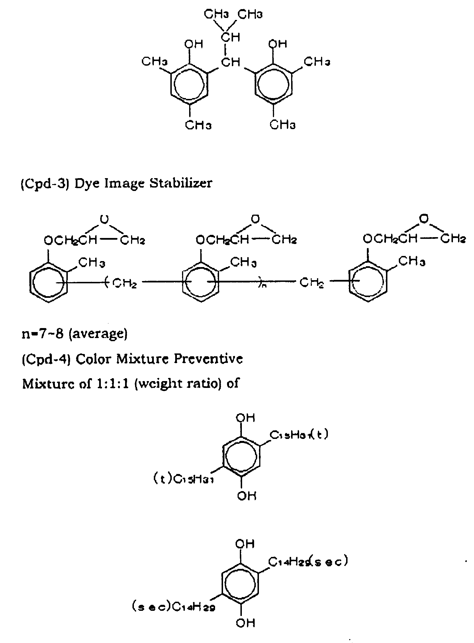


- The flow rate per unit width of each free falling coating solution film was adjusted so as to become q = 3, 4, 5, 6 (cc/cm/s) by adding water without changing the coating amount of the composition of respective layers, and their viscosity was adjusted by adding sodium polystyrene sulfonate as a thickner.
- Coating tests were carried out with varying the relation between the contact angle of water with the coating width regulating plate and that with the edge guide, and surface quality of each coating was evaluated as to the uneven thickness at side ends of free falling liquid film and the occurrence of streaks.
- The material of the coating width regulating plate and the edge guide were selected from stainless steel (SUS), acrylic resin (Acrylic), polyvinyl chloride (PVC) and polytetrafluoroethylene (PTFE).
- In Examples 1 through 6 which were carried out under the conditions satisfying the formula (contact angle of water with coating width regulating plate) > (Contact angle of water with edge guide), coating surface quality was excellent, in every example.
- Conversely, in Comparative Examples / through 6 which were carried out under the conditions of the formula (contact angle of water with coating width regulating plate) < (Contact angle of water with edge guide), strong streaks and uneven thickness at film edge portions occurred.
- In Comparative Examples 7 through 10 wherein the material of the edge guide was the same as the material of the coating width regulating plate, i.e. (contact angle of water with coating width regulating plate) = (Contact angle of water with edge guide), weak streaks and uneven thickness at film edge portions occurred.
- In addition, in the case that the contact angle of water with the edge guide was the same as that with the coating width regulating plate, similar results were obtained, irrespective of coating amount.
- The results are summarized in Table 1.
Material of Width Regulating Plate Material of Edge Guide SUS Acrylic PVC PTFE SUS Comp. Ex. 7 ▵ Comp. Ex. 1 X Comp. Ex. 2 X Comp. Ex. 3 X Acrylic Ex. 1 ○ Comp. Ex. 8 ▵ Comp. Ex. 4 X Comp. Ex. 5 X PVC Ex. 2 ○ Ex. 3 ○ Comp. Ex. 9 ▵ Comp. Ex. 6 X PTFE Ex. 4 ○ Ex. 5 ○ Ex. 6 ○ Comp. Ex. 10 ▵ ○ ... Good coating face quality
▵ ... Weak streaks and uneven thickness at film and portions
X ... Strong streaks and uneven thickness at film and portions
Contact Angle against Water :
SUS : 20 degrees
Acrylic : 80 degrees
PVC : 87 degrees
PTFE : 108 degrees - It can be seen from the above results that, by selecting a combination satisfying the conditions of (Contact angle of water with a coating width regulating plate) > (Contact angle of water with an edge guide) as the material of the coating width regulating plate and the edge guide, the occurrence of streaks and the occurrence of uneven thickness at film edge portions can easily be inhibited.
- Subsequently, effects of the height of the vertical face were examined. The material of the coating width regulating plate was polyvinyl chloride (PVC) or polytetrafluoroethylene (PTFE), and the material of the edge guide was stainless steel (SUS), acrylic resin (Acrylic) or polyvinyl chloride (PVC). The angle of the inclined face was 45 degrees. The results are shown in Table 2.
- In Examples 7 and 8 and Comparative Examples 11 and 12, the contact angle of water with the coating width regulating plate was less than 95 degrees. In this case, when the height of the vertical face was less than 3 mm as shown in Examples 7 and 8, the coating face quality was good. However, when the height of the vertical face was 3 mm or more as shown in Comparative Examples 11 and 12, streaks and uneven thickness at film edge portions occurred (Table 2).
- On the other hand, in Examples 9 and 10 and Comparative Examples 13 and 14, the contact angle of water with the coating width regulating plate was 95 degrees or more. In this case, when the height of the vertical face was 3 mm or more as shown in Examples 9 and 10, the coating face quality was good. However, when the height of the vertical face was 3 mm or more as shown in Comparative Examples 13 and 14, streaks and uneven thickness at film edge portions occurred (Table 2).
- In the case that the relation of the contact angle and the height of the vertical face were not changed, similar results were obtained, irrespective of coating amount.
- The results are summarized in Table 2
Material Vertical Face Height (mm) Coating Face Quality Regulating Plate Edge Guide Example 7 PVC SUS 1 Good Example 8 PVC Acrylic 1 Good Comparative 11 PVC SUS 4 Trouble Comparative 12 PVC Acrylic 4 Trouble Example 9 PTFE PVC 4 Good Example 10 PTFE SUS 4 Good Comparative 13 PTFE PVC 1 Trouble Comparative 14 PTFE SUS 1 Trouble Trouble: Streaks and uneven thickness at film edge portions occurred.
Contact Angle against Water
SUS : 20 degrees
Acrylic : 80 degrees
PVC : 87 degrees
PTFE : 108 degrees - It can be seen from the above results that, the occurrence of streaks and uneven thickness at film edge portions can be inhibited by making the vertical face height less tan 3 mm for the contact angle of water with the coating width regulating plate of less than 95 degrees and by making the
vertical face height 3 mm or more for the contact angle of water with the coating width regulating plate of 95 degrees or more. - Furthermore, the angle of the inclined face was changed, and coating tests were carried out under the conditions of Example 2.
- The results are shown in Table 3.
Angle (degree) Coating Face Quality Example 11 30 Good Example 12 50 Good Example 13 60 Good Comparative 15 15 Trouble Comparative 16 80 Trouble Trouble: Streaks and uneven thickness at film edge portion occurred. - As can be seen from Table 3, it can be seen that a preferable angle of the inclined face is in the range of 30 to 60 degrees.
Claims (7)
- A curtain coating apparatus which comprises a sliding face on which a coating solution flows down, a coating width regulating plate which is located on each of both sides of the sliding face and regulates the width of the flow of the coating solution, and an edge guide which is connected to the width regulating plate, and keeps both side edges of free falling stream of the coating solution from the sliding face, wherein a contact angle of water with the coating width regulating plate is greater than a contact angle of water with the edge guide.
- The curtain coating apparatus of claim 1, wherein a contact angle of water with the coating width regulating plate is greater than a contact angle of water with the edge guide by 1 by 100 degrees.
- The curtain coating apparatus of claim 1, wherein the coating width regulating plate has a lower vertical face and an upper inclined face inclined toward the outside connected to the vertical face on the coating solution stream side.
- The curtain coating apparatus of claim 3, wherein the contact angle of water with the coating width regulating plate is. less than 95 degrees, and the vertical face has a height of less than 3 mm.
- The curtain coating apparatus of claim 3, wherein the contact angle of water with the coating width regulating plate is 95 degrees or more, and the vertical face has a height of 3 mm or more.
- The curtain coating apparatus of claim 4, wherein the inclined face has an angle of inclination of 30 to 60 degrees.
- The curtain coating apparatus of claim 5, wherein the inclined face has an angle of inclination of 30 to 60 degrees.
Applications Claiming Priority (2)
| Application Number | Priority Date | Filing Date | Title |
|---|---|---|---|
| JP16847399 | 1999-06-15 | ||
| JP11168473A JP2000354813A (en) | 1999-06-15 | 1999-06-15 | Curtain coater |
Publications (2)
| Publication Number | Publication Date |
|---|---|
| EP1061412A1 true EP1061412A1 (en) | 2000-12-20 |
| EP1061412B1 EP1061412B1 (en) | 2006-12-06 |
Family
ID=15868766
Family Applications (1)
| Application Number | Title | Priority Date | Filing Date |
|---|---|---|---|
| EP00112609A Expired - Lifetime EP1061412B1 (en) | 1999-06-15 | 2000-06-14 | Curtain coating apparatus |
Country Status (4)
| Country | Link |
|---|---|
| US (1) | US6454858B1 (en) |
| EP (1) | EP1061412B1 (en) |
| JP (1) | JP2000354813A (en) |
| DE (1) | DE60032195T2 (en) |
Cited By (1)
| Publication number | Priority date | Publication date | Assignee | Title |
|---|---|---|---|---|
| EP1331039A1 (en) * | 2002-01-24 | 2003-07-30 | Fuji Photo Film Co., Ltd. | Coating apparatus and method for applying coating solution on web |
Families Citing this family (5)
| Publication number | Priority date | Publication date | Assignee | Title |
|---|---|---|---|---|
| DE10117668A1 (en) * | 2001-04-09 | 2002-10-10 | Bachofen & Meier Ag Buelach | Device for coating a running material web |
| DE50209547D1 (en) * | 2002-09-10 | 2007-04-05 | Ilford Imaging Ch Gmbh | Method and apparatus for curtain coating a moving support |
| AU2005285221B2 (en) * | 2004-09-09 | 2010-11-11 | Avery Dennison Corporation | Curtain coating method |
| JP5088317B2 (en) * | 2006-03-30 | 2012-12-05 | 日本ゼオン株式会社 | Developer for developing positively charged electrostatic image and method for producing the same |
| JP6300399B2 (en) * | 2014-01-15 | 2018-03-28 | ユニバーサル製缶株式会社 | Can body inner surface coating device |
Citations (6)
| Publication number | Priority date | Publication date | Assignee | Title |
|---|---|---|---|---|
| US3632403A (en) * | 1969-03-26 | 1972-01-04 | Eastman Kodak Co | Method and apparatus for curtain coating |
| DE2542819A1 (en) * | 1974-11-04 | 1976-04-15 | Ciba Geigy Ag | COATING DEVICE |
| JPS63287575A (en) * | 1987-05-19 | 1988-11-24 | Fuji Photo Film Co Ltd | Coating equipment |
| EP0796666A2 (en) * | 1996-03-21 | 1997-09-24 | Konica Corporation | Light-sensitive material production method |
| JPH10309506A (en) * | 1997-05-12 | 1998-11-24 | Mitsubishi Paper Mills Ltd | Application method |
| JP2000126663A (en) * | 1998-10-27 | 2000-05-09 | Mitsubishi Paper Mills Ltd | Curtain coating device and coating method |
Family Cites Families (3)
| Publication number | Priority date | Publication date | Assignee | Title |
|---|---|---|---|---|
| US5338359A (en) * | 1993-11-03 | 1994-08-16 | Eastman Kodak Company | Hopper preparation pan with edge walls |
| US5837324A (en) * | 1996-05-31 | 1998-11-17 | Minnesota Mining And Manufacturing Company | Profiled edge guide |
| EP0850696B1 (en) * | 1996-12-26 | 2002-08-07 | Konica Corporation | Process for coating a light-sensitive material |
-
1999
- 1999-06-15 JP JP11168473A patent/JP2000354813A/en active Pending
-
2000
- 2000-06-14 DE DE60032195T patent/DE60032195T2/en not_active Expired - Lifetime
- 2000-06-14 EP EP00112609A patent/EP1061412B1/en not_active Expired - Lifetime
- 2000-06-15 US US09/593,951 patent/US6454858B1/en not_active Expired - Lifetime
Patent Citations (6)
| Publication number | Priority date | Publication date | Assignee | Title |
|---|---|---|---|---|
| US3632403A (en) * | 1969-03-26 | 1972-01-04 | Eastman Kodak Co | Method and apparatus for curtain coating |
| DE2542819A1 (en) * | 1974-11-04 | 1976-04-15 | Ciba Geigy Ag | COATING DEVICE |
| JPS63287575A (en) * | 1987-05-19 | 1988-11-24 | Fuji Photo Film Co Ltd | Coating equipment |
| EP0796666A2 (en) * | 1996-03-21 | 1997-09-24 | Konica Corporation | Light-sensitive material production method |
| JPH10309506A (en) * | 1997-05-12 | 1998-11-24 | Mitsubishi Paper Mills Ltd | Application method |
| JP2000126663A (en) * | 1998-10-27 | 2000-05-09 | Mitsubishi Paper Mills Ltd | Curtain coating device and coating method |
Non-Patent Citations (3)
| Title |
|---|
| DATABASE WPI Section PQ Week 200033, Derwent World Patents Index; Class P42, AN 2000-380481, XP002150379 * |
| PATENT ABSTRACTS OF JAPAN vol. 013, no. 111 (C - 577) 16 March 1989 (1989-03-16) * |
| PATENT ABSTRACTS OF JAPAN vol. 1999, no. 02 26 February 1999 (1999-02-26) * |
Cited By (2)
| Publication number | Priority date | Publication date | Assignee | Title |
|---|---|---|---|---|
| EP1331039A1 (en) * | 2002-01-24 | 2003-07-30 | Fuji Photo Film Co., Ltd. | Coating apparatus and method for applying coating solution on web |
| US6986916B2 (en) | 2002-01-24 | 2006-01-17 | Fuji Photo Film Co., Ltd. | Coating apparatus and method for applying coating solution on web |
Also Published As
| Publication number | Publication date |
|---|---|
| DE60032195T2 (en) | 2007-03-29 |
| US6454858B1 (en) | 2002-09-24 |
| DE60032195D1 (en) | 2007-01-18 |
| JP2000354813A (en) | 2000-12-26 |
| EP1061412B1 (en) | 2006-12-06 |
Similar Documents
| Publication | Publication Date | Title |
|---|---|---|
| US6458422B2 (en) | Method for coating a plurality of fluid layers onto a substrate | |
| EP0003860A1 (en) | Method for applying a plurality of superposed photographic layers to a web by curtain coating | |
| EP0390774B1 (en) | High speed curtain coating process and apparatus | |
| US5843530A (en) | Method for minimizing waste when coating a fluid with a slide coater | |
| JPS6064662A (en) | Coating method | |
| EP1061412A1 (en) | Curtain coating apparatus | |
| US6287384B2 (en) | Curtain coating method and apparatus for photographic printing paper | |
| EP0836117B1 (en) | Curtain coating method | |
| AU653090B2 (en) | Curtain coating device | |
| JPS6247075B2 (en) | ||
| JP3727940B2 (en) | Photographic paper curtain coating method | |
| US6986916B2 (en) | Coating apparatus and method for applying coating solution on web | |
| JPH0777773A (en) | Coating device for color photosensitive material and coating method thereof | |
| JPH11207229A (en) | Curtain coater | |
| JPH10171064A (en) | Curtain coating method for photographic paper | |
| JPS59189967A (en) | Application of paint | |
| JPH06170307A (en) | Apparatus for applying multilayer simultaneously and application method | |
| JPH10202157A (en) | Slide application device and manufacture of photosensitive material using this device | |
| JPH0764234A (en) | Method for simultaneously applying multiple layers | |
| JPH02277570A (en) | Applicator | |
| JPH08257483A (en) | Application method | |
| JPH10115890A (en) | Curtain coating application method of photographic sensitive material | |
| JPH0494763A (en) | Dip coating method | |
| JPH06194782A (en) | Method for applying photosensitive material | |
| CN1355069A (en) | Screen coating machine |
Legal Events
| Date | Code | Title | Description |
|---|---|---|---|
| PUAI | Public reference made under article 153(3) epc to a published international application that has entered the european phase |
Free format text: ORIGINAL CODE: 0009012 |
|
| AK | Designated contracting states |
Kind code of ref document: A1 Designated state(s): DE |
|
| AX | Request for extension of the european patent |
Free format text: AL;LT;LV;MK;RO;SI |
|
| 17P | Request for examination filed |
Effective date: 20010607 |
|
| AKX | Designation fees paid |
Free format text: DE |
|
| GRAP | Despatch of communication of intention to grant a patent |
Free format text: ORIGINAL CODE: EPIDOSNIGR1 |
|
| GRAS | Grant fee paid |
Free format text: ORIGINAL CODE: EPIDOSNIGR3 |
|
| GRAA | (expected) grant |
Free format text: ORIGINAL CODE: 0009210 |
|
| AK | Designated contracting states |
Kind code of ref document: B1 Designated state(s): DE |
|
| REF | Corresponds to: |
Ref document number: 60032195 Country of ref document: DE Date of ref document: 20070118 Kind code of ref document: P |
|
| RAP2 | Party data changed (patent owner data changed or rights of a patent transferred) |
Owner name: FUJIFILM CORPORATION |
|
| PLBE | No opposition filed within time limit |
Free format text: ORIGINAL CODE: 0009261 |
|
| STAA | Information on the status of an ep patent application or granted ep patent |
Free format text: STATUS: NO OPPOSITION FILED WITHIN TIME LIMIT |
|
| 26N | No opposition filed |
Effective date: 20070907 |
|
| PGFP | Annual fee paid to national office [announced via postgrant information from national office to epo] |
Ref country code: DE Payment date: 20150609 Year of fee payment: 16 |
|
| REG | Reference to a national code |
Ref country code: DE Ref legal event code: R119 Ref document number: 60032195 Country of ref document: DE |
|
| PG25 | Lapsed in a contracting state [announced via postgrant information from national office to epo] |
Ref country code: DE Free format text: LAPSE BECAUSE OF NON-PAYMENT OF DUE FEES Effective date: 20170103 |