EP1061397A2 - Wide-angle catoptric system - Google Patents
Wide-angle catoptric system Download PDFInfo
- Publication number
- EP1061397A2 EP1061397A2 EP00112162A EP00112162A EP1061397A2 EP 1061397 A2 EP1061397 A2 EP 1061397A2 EP 00112162 A EP00112162 A EP 00112162A EP 00112162 A EP00112162 A EP 00112162A EP 1061397 A2 EP1061397 A2 EP 1061397A2
- Authority
- EP
- European Patent Office
- Prior art keywords
- reflecting mirror
- wide
- tertiary
- optical axis
- primary
- Prior art date
- Legal status (The legal status is an assumption and is not a legal conclusion. Google has not performed a legal analysis and makes no representation as to the accuracy of the status listed.)
- Granted
Links
Images


Classifications
-
- G—PHYSICS
- G02—OPTICS
- G02B—OPTICAL ELEMENTS, SYSTEMS OR APPARATUS
- G02B17/00—Systems with reflecting surfaces, with or without refracting elements
- G02B17/02—Catoptric systems, e.g. image erecting and reversing system
- G02B17/06—Catoptric systems, e.g. image erecting and reversing system using mirrors only, i.e. having only one curved mirror
- G02B17/0626—Catoptric systems, e.g. image erecting and reversing system using mirrors only, i.e. having only one curved mirror using three curved mirrors
- G02B17/0642—Catoptric systems, e.g. image erecting and reversing system using mirrors only, i.e. having only one curved mirror using three curved mirrors off-axis or unobscured systems in which not all of the mirrors share a common axis of rotational symmetry, e.g. at least one of the mirrors is warped, tilted or decentered with respect to the other elements
Definitions
- the present invention relates to a wide-angle catoptric system, which is used in cameras having wide-angled fields of view for observations, inspections and so forth, and which forms images of objects.
- optical elements having such refractive action include, for instance, lenses bending light by using the difference in refractive indexes, reflecting mirrors bending light by using reflection, and so forth.
- lenses should be made of a material having sufficient transmittance for a desirable wavelength band.
- wavelength bands such as ultraviolet rays and infrared rays
- the materials of lenses are limited to expensive types.
- the refractive index of lens materials usually has chromatic aberration that is different in size depending on the wavelength of light, so that a complex correction, the so-called achromatism, has to be carried out by combining two or more lenses having different refractive index changes in respect to a wavelength, or the like, in order to provide consistent imaging properties over a broad wavelength band.
- reflecting mirrors There is no limitation on the materials for reflecting mirrors as long as their reflecting surfaces can be coated with a reflecting material having sufficient properties, so that economical optical systems may be obtained for any wavelength band. Additionally, since reflection does not rely on the wavelength of light, reflecting mirrors have no chromatic aberration and an optical system, having consistent imaging properties over a broad wavelength band, may be easily obtained.
- incident beams are tilted relative to an optical axis so as to provide an angle between the input direction and the output direction of beams.
- the following reflecting mirror is usually deposited in the output direction of beams, so that the following reflecting mirror will not overlap the incident beams if the input direction and the output direction of beams are different with an angle therebetween, thus not generating shading.
- optical systems are generally designed on the basis of paraxial imaging that is achieved when incident beams are parallel to an axis of the optical systems. Accordingly, paraxial imaging will be out of focus if incident beams are tilted relative to an optical axis, thus intensifying aberration. Images will be blurred and picture quality will deteriorate, as aberration increases.
- FIG. 5 is a conventional wide-angle catoptric system disclosed in U.S. Patent 4,598,981: "WIDE-ANGLE FLAT FIELD TELESCOPE".
- the system has a brightness of F/4 and a field of view of 30° times 20° .
- a primary reflecting mirror 1 has a convex spherical surface.
- a secondary reflecting mirror 2 has a concave ellipsoidal surface.
- a tertiary reflecting mirror 3 has a concave spherical surface.
- a circular diaphragm 4 is placed in close proximity to the primary reflecting mirror 1.
- a luminous flux 5 is the flux of incident beams to the primary reflecting mirror 1
- a luminous flux 6 is the flux of output beams from the secondary reflecting mirror 2.
- An optical axis 7 is a straight line connecting the curvature center of the primary reflecting mirror 1 to the curvature center of the secondary reflecting mirror 2.
- the center of curvature of the tertiary reflecting mirror 3 and the center of the diaphragm are also on the axis 7, providing a co-axial configuration. Tilting incident beams relative to the optical axis 7 prevents the shading caused by overlapping beams.
- the major aberrations deteriorating the picture quality of images are spherical aberration, coma, field curvature, and astigmatism.
- the wide-angle catoptric system mentioned above reduces each aberration.
- Spherical aberration is caused by the deviation of focal positions between central beams and peripheral beams.
- optical parameters are determined to provide almost the same deviation of a focal position of peripheral beams by the secondary reflecting mirror 2 as the deviation of a focal position of peripheral beams by the tertiary reflecting mirror 3 in the reverse direction, so that the deviations cancel each other, reducing spherical aberration. Accordingly, the spherical aberration by the primary reflecting mirror 1 still remains.
- Coma is caused by the deviation of focal positions between central beams and peripheral beams for the light input with an angle relative to the optical axis 7.
- the above-mentioned wide-angle catoptric system determines optical parameters so as to mutually cancel the deviations at all three mirrors, the primary reflecting mirror 1, the secondary reflecting mirror 2 and the tertiary reflecting mirror 3, thus reducing coma.
- Field curvature is the phenomenon whereby an image plane is curved with a curvature, and the radius of curvature thereof is expressed in a so-called Petzval sum.
- the radii of curvatures of the primary reflecting mirror 1, the secondary reflecting mirror 2 and the tertiary reflecting mirror 3 are set so as to provide a zero Petzval sum, thus providing a zero curvature of the image plane and eliminating a field curvature.
- Astigmatism is found for the light, which is input with an angle relative to the optical axis 7, when reflecting mirrors have different shapes between the tangential direction and the sagittal direction, and appears as the difference in curvature radii of an image plane between the tangential direction and the sagittal direction.
- optical parameters are determined to provide almost the same difference in curvature radii of the image plane at the primary reflecting mirror 1 as the difference in curvature radii of the image plane at the tertiary reflecting mirror 3 in the reverse direction, so that the differences cancel each other, reducing astigmatism.
- the astigmatism by the secondary reflecting mirror 2 still exists.
- the aperture of the diaphragm 4 should be widened so as to increase the quantity of incident light.
- a luminous flux is broadened by enlarging the aperture of the diaphragm 4
- shading will occur.
- the luminous flux 5 of incident beams to the primary reflecting mirror 1 and the luminous flux 6 of output beams from the secondary reflecting mirror 2 are in close proximity. Therefore, as the two luminous fluxes overlap each other by broadening the luminous flux, shading will occur at the overlapping section thereof.
- a wide-angle catoptric system includes, successively from an object, a secondary reflecting mirror having a concave surface, a primary reflecting mirror having a convex surface and a tertiary reflecting mirror having a concave surface, and produces images by reflecting the luminous flux incident from the object at the primary reflecting mirror, the secondary reflecting mirror and the tertiary reflecting mirror successively.
- the system also includes a diaphragm arranged in close proximity to the primary reflecting mirror so as to have an optical axis pass through the center of the diaphragm; the optical axis is a straight line connecting the curvature center of the primary reflecting mirror to the curvature center of the secondary reflecting mirror.
- the tertiary reflecting mirror has its center of curvature decentered from the optical axis in the direction of lesser astigmatism.
- the tertiary reflecting mirror is moved in parallel to a surface which is orthogonal to the optical axis, thus decentering the curvature center thereof from the optical axis.
- the tertiary reflecting mirror may be arranged with its reflecting surface tilted from a surface which is orthogonal to the optical axis, in the direction of lesser astigmatism.
- a wide-angle catoptric system includes, successively from an object, a secondary reflecting mirror having a concave surface, a primary reflecting mirror having a convex surface and a tertiary reflecting mirror having a concave surface, and produces images by reflecting the luminous influx incident from the object at the primary reflecting mirror, the secondary reflecting mirror and the tertiary reflecting mirror successively.
- the system also includes a diaphragm arranged in close proximity to the primary reflecting mirror so as to have an optical axis pass through the center of the diaphragm; the optical axis is a straight line connecting the curvature center of the primary reflecting mirror to the curvature center of the secondary reflecting mirror.
- the tertiary reflecting mirror has its curvature center on the optical axis, and the reflecting surface thereof is tilted from a surface which is orthogonal to the optical axis, in the direction of lesser astigmatism.
- At least one of the primary reflecting mirror, the secondary reflecting mirror and the tertiary reflecting mirror has an aspherical surface.
- system may further include an aberration correction plate in close proximity to the diaphragm so as to reduce spherical aberration.
- the diaphragm may be non-circular.
- the diaphragm is preferably in one body with the primary reflecting mirror.
- FIG. 1 is a cross-sectional view of a wide-angle catoptric system according to a first embodiment of the present invention.
- a primary reflecting mirror 1 has a convex spherical surface.
- a secondary reflecting mirror 2 has a concave spherical surface.
- a tertiary reflecting mirror 3 has a concave spherical surface.
- a circular diaphragm 4 is located in close proximity to the primary reflecting mirror 1.
- a luminous flux 5 is the flux of incident beams to the primary reflecting mirror 1
- a luminous flux 6 is the flux of the output beams from the secondary reflecting mirror 2.
- An optical axis 7 is a straight line connecting the curvature center of the primary reflecting mirror 1 to the curvature center of the secondary reflecting mirror 2.
- the center of the diaphragm 4 is on the optical axis 7.
- the center of curvature of the tertiary reflecting mirror 3 is not on the optical axis 7 and the mirror is decentered.
- the parallel direction of movement for the tertiary reflecting mirror 3 is the direction of an arrow y in FIG. 1 (the y direction is the orthogonal direction to the axis 7 in a plane, including the optical axis 7, where a luminous flux is output by the tertiary reflecting mirror 3), and the direction that is orthogonal to the y direction and the optical axis 7 is the x direction.
- Incident beams are tilted relative to the optical axis 7 in the y direction, thus preventing shading caused by overlapping beams.
- the F-number which indicates the brightness of the wide-angle catoptric system, is in inverse proportion to the aperture size of the diaphragm 4 and is in proportion to focal lengths. Therefore, in order to provide a bright optical system with a small F-number, the aperture of the diaphragm 4 may be widened, or the focal length may be shortened. However, a luminous flux becomes wider as the aperture of the diaphragm 4 is enlarged, thus mutually overlapping the luminous flux 5 with the luminous flux 6, resulting in shading. Thus, a bright optical system can be provided by shortening focal lengths in this wide-angle catoptric system.
- the power of a reflecting mirror having positive power may be increased while the power of a reflecting mirror having negative power may be reduced.
- the power of the primary reflecting mirror 1 may be reduced while the power of the secondary reflecting mirror 2 and the tertiary reflecting mirror 3 may be increased.
- the luminous flux 5 of incident beams to the primary reflecting mirror 1 widens, thus mutually overlapping the luminous flux 5 with the luminous flux 6 and resulting in shading. Accordingly, by reducing the curvature radius of the tertiary reflecting mirror 3 and increasing the power, a bright optical system having a short focal length may be provided in the above-noted wide-angle catoptric system.
- the major aberrations deteriorating the picture quality of images are spherical aberration, coma, field curvature, and astigmatism.
- the wide-angle catoptric system mentioned above reduces each aberration.
- Spherical aberration is caused by the deviation of focal positions between central beams and peripheral beams.
- optical parameters are determined so as to mutually cancel the deviations of focal positions of peripheral beams at all three mirrors, the primary reflecting mirror 1, the secondary reflecting mirror 2 and the tertiary reflecting mirror 3, thus minimizing spherical aberration to an acceptable level.
- Coma is caused by the deviation of focal positions between central beams and peripheral beams for the light input with an angle relative to the optical axis 7.
- Coma is based on the spherical aberration mentioned above and the location of an optical pupil.
- the scale of coma changes in accordance with the location of a pupil.
- coma is canceled by placing a pupil at a suitable location for the above-mentioned acceptably minimized spherical aberration.
- Field curvature is the phenomenon whereby an image plane has a curvature, and the radius of curvature thereof is expressed in the so-called Petzval sum.
- this aberration is corrected by minimizing the Petzval sum to provide an almost flat image plane and, moreover, by tilting the image plane in accordance with the curve.
- astigmatism is particularly a problem. Astigmatism is caused when the shapes of reflecting mirrors for incident beams are different between a tangential direction and a sagittal direction. Specifically, astigmatism is zero for the beams vertically input to a reflecting mirror, and astigmatism increases as the tilted angle of input beams becomes large.
- astigmatism becomes large as the curvature radius of a reflecting mirror becomes smaller.
- astigmatism becomes large on the tertiary reflecting mirror 3 since the curvature radius of the tertiary reflecting mirror 3 is small.
- Astigmatism appears as the difference in the curvature radii of an image plane between the tangential direction and the sagittal direction.
- the differences in curvature radii cancel each other at all three mirrors, the primary reflecting mirror 1, the secondary reflecting mirror 2 and the tertiary reflecting mirror 3. Furthermore, by moving the tertiary reflecting mirror 3 parallel to the y direction, the incident beams to the reflecting mirror are made nearly vertical, minimizing astigmatism. Since astigmatism increases in proportion to the square of an angle of incident beams to the reflecting mirror, the angle of incident beams can be reduced, for instance, by tilting the tertiary reflecting mirror 3 in the direction of lesser astigmatism; in other words, in the direction where the incident beams become nearly vertical, thereby reducing astigmatism.
- the tertiary reflecting mirror 3 is moved parallel to the y direction in the wide-angle catoptric system mentioned above, the same effect can also be obtained by tilting the tertiary reflecting mirror 3 in the direction of lesser astigmatism. There is no doubt that the tertiary reflecting mirror 3 can be moved parallel to the y direction and can be tilted in the direction of lesser astigmatism at the same time.
- the surfaces of the primary reflecting mirror 1, the secondary reflecting mirror 2 and the tertiary reflecting mirror 3 are all spherical in this embodiment, they can also be aspherical.
- the spherical aberration generated by brightening an optical system for instance, may be corrected with high precision.
- the spherical aberration results from spherical reflecting surfaces, and may not be fully corrected solely by spherical reflecting mirrors.
- Any of the primary reflecting mirror 1, the secondary reflecting mirror 2 and the tertiary reflecting mirror 3 may have an aspherical surface, or a plurality of the mirror surfaces may be aspherical.
- An aberration correction plate may be provided in close proximity to the diaphragm 4 in addition to, or instead of shaping a reflecting mirror in an aspherical shape as mentioned above.
- FIG. 2 shows a wide-angle catoptric system whereby a transmission-type aberration correction plate using the refractive action of light is inserted.
- the reference numerals 1 to 8 are the same as the ones in FIG. 1.
- An aberration correction plate 9 is deposited in close proximity to the diaphragm 4.
- This aberration correction plate 9 is particularly effective in correcting spherical aberration with high precision.
- the plate has a small refractive action of bending light, the deterioration of picture quality is small even in case of materials having chromatic aberration.
- a material capable of transmitting light having a desirable wavelength may be used for the aberration correction plate 9.
- the aberration correction plate 9 is a transmission type using the refractive action of light in FIG. 2, the aberration correction plate may be a reflecting mirror as long as it performs a similar function to correct aberration.
- FIG. 3 shows MTF (Modulation Transfer Function) of the wide-angle catoptric system in this embodiment, and the standard wavelength of incident beams is 10 ⁇ m.
- the wide-angle catoptric system has a focal length of 25 mm, a field of view of 30° times 22° , and F/2.5.
- Incident beams are input with an angle of 44° ⁇ 11° relative to the optical axis 7 in the y direction.
- F/2.5 is the value on the optical axis 7. Since the incident beams have an angle in respect to the optical axis 7 as described above, the actual F is 2.7. According to FIG. 3, the diffraction limit can be nearly obtained.
- the diaphragm 4 is circular. Since a luminous flux is broadened by widening the diaphragm 4 in the y direction, the luminous flux 5 of incident beams to the primary reflecting mirror 1 and the luminous flux 6 of the output beams from the secondary reflecting mirror 6 overlap each other, resulting in shading. On the contrary, the luminous fluxes do not mutually overlap as the diaphragm is opened in the x direction, thus causing no shading. Therefore, a bright optical system can be provided without shading by broadening a luminous flux in the x direction with an elliptical diaphragm having a long axis in the x direction, or the like.
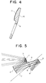
- FIG. 4 is a cross-sectional view, showing a portion of a wide-angle catoptric system in Third Embodiment.
- a substrate 10 of the primary reflecting mirror 1 is formed in one body with the diaphragm 4.
- a reflecting member 11 is the reflecting surface of the primary reflecting mirror 1.
- Other components are the same as those in First Embodiment.
- the number of components may be reduced and the manufacturing procedure as well as the assembling procedure of components may be simplified. Moreover, since there is no tolerance between integrated components during the assembling process, a wide-angle catoptric system may be easily assembled as a whole.
- the wide-angle catoptric system includes, successively from an object, a secondary reflecting mirror having a concave surface, a primary reflecting mirror having a convex surface and a tertiary reflecting mirror having a concave surface, and produces images by reflecting the luminous influx input from the object at the primary reflecting mirror, the secondary reflecting mirror and the tertiary reflecting mirror successively.
- the system also includes a diaphragm arranged in close proximity to the primary reflecting mirror so as to have an optical axis pass through the center of the diaphragm; the optical axis is a straight line connecting the curvature center of the primary reflecting mirror to the curvature center of the secondary reflecting mirror.
- the tertiary reflecting mirror has its center of curvature decentered from the optical axis in the direction of lesser astigmatism. Accordingly, the system can reduce astigmatism and will not deteriorate the picture quality of images.
- the tertiary reflecting mirror may be moved in parallel to a surface which is orthogonal to the optical axis, thus decentering the center of curvature thereof from the optical axis. Therefore, the system can reduce astigmatism and will not deteriorate the picture quality of images.
- the tertiary reflecting mirror is preferably arranged with its reflecting surface tilted from a surface which is orthogonal to the optical axis, in the direction of lesser astigmatism.
- the system can further reduce astigmatism and will not deteriorate the picture quality of images.
- the wide-angle catoptric system includes, successively from an object, a secondary reflecting mirror having a concave surface, a primary reflecting mirror having a convex surface and a tertiary reflecting mirror having a concave surface, and produces images by reflecting the luminous flux input from the object at the primary reflecting mirror, the secondary reflecting mirror and the tertiary reflecting mirror successively.
- the system also includes a diaphragm arranged in close proximity to the primary reflecting mirror so as to have an optical axis pass through the center of the diaphragm; as the optical axis is a straight line connecting the curvature center of the primary reflecting mirror to the curvature center of the secondary reflecting mirror.
- the tertiary reflecting mirror has its curvature center on the optical axis, and the reflecting surface thereof is tilted from a surface which is orthogonal to the optical axis, in the direction of lesser astigmatism.
- the system can reduce astigmatism and will not deteriorate the picture quality of images.
- At least one of the primary reflecting mirror, the secondary reflecting mirror and the tertiary reflecting mirror may have an aspherical surface. Accordingly, the spherical aberration generated by brightening the optical system can be corrected with high precision.
- the system may further include an aberration correction plate in close proximity to the diaphragm so as to reduce spherical aberration.
- an aberration correction plate in close proximity to the diaphragm so as to reduce spherical aberration.
- the spherical aberration can be corrected with high precision.
- the diaphragm may be non-circular. Therefore, a luminous flux can be broadened, and a bright optical system can be provided without shading.
- the diaphragm may be in one body with the primary reflecting mirror. Accordingly, the number of components may be reduced, and the manufacturing procedure and the assembling procedure of components may be simplified. In addition, since there is no tolerance for integrated components during the assembling process, the wide-angle catoptric system may be easily assembled as a whole.
Landscapes
- Physics & Mathematics (AREA)
- General Physics & Mathematics (AREA)
- Optics & Photonics (AREA)
- Lenses (AREA)
- Stereoscopic And Panoramic Photography (AREA)
Abstract
Description
Claims (8)
- A wide-angle catoptric system comprising, successively from an object, a secondary reflecting mirror (2) having a concave surface, a primary reflecting mirror (1) having a convex surface and a tertiary reflecting mirror (3) having a concave surface wherein images are formed by reflecting a luminous flux incident from the object at said primary reflecting mirror (1), said secondary reflecting mirror (2) and said tertiary reflecting mirror (3) successively; and a diaphragm (4) arranged in close proximity to said primary reflecting mirror (1) so as to have an optical axis (7), which is a straight line connecting a curvature center of said primary reflecting mirror (1) to a curvature center of said secondary reflecting mirror (2), pass through a center of the diaphragm (4); wherein said tertiary reflecting mirror (3) has a center of curvature thereof decentered from said optical axis (7) in a direction of lesser astigmatism.
- The wide-angle catoptric system according to Claim 1, wherein said tertiary reflecting mirror (3) is moved in parallel to a surface which is orthogonal to said optical axis (7) so as to decenter a center of curvature thereof from said optical axis (7).
- The wide-angle catoptric system according to one of Claim 1 and Claim 2, wherein said tertiary reflecting mirror (3) is arranged with a reflecting surface thereof tilted from a surface which is orthogonal to said optical axis (7), in a direction of lesser astigmatism.
- A wide-angle catoptric system comprising, successively from an object, a secondary reflecting mirror (2) having a concave surface, a primary reflecting mirror (1) having a convex surface and a tertiary reflecting mirror (3) having a concave surface wherein images are formed by reflecting a luminous flux incident from the object at said primary reflecting mirror (1), said secondary reflecting mirror (2) and said tertiary reflecting mirror (3) successively; and a diaphragm (4) arranged in close proximity to said primary reflecting mirror (1) so as to have an optical axis (7), which is a straight line connecting a curvature center of said primary reflecting mirror (1) to a curvature center of said secondary reflecting mirror (2), pass through a center of the diaphragm (4); wherein said tertiary reflecting mirror (3) has a center of curvature thereof on said optical axis (7) and a reflecting surface thereof is tilted from a surface which is orthogonal to said optical axis (7) in a direction of lesser astigmatism.
- The wide-angle catoptric system according to one of Claim 1, 2, 3, and 4, wherein at least one of said primary reflecting mirror (1), said secondary reflecting mirror (2) and said tertiary reflecting mirror (3) has an aspherical surface.
- The wide-angle catoptric system according to one of Claim 1, 2, 3, 4, and 5, further comprising an aberration correction plate (9) in close proximity to said diaphragm (4) so as to reduce spherical aberration.
- The wide-angle catoptric system according to one of Claim 1, 2, 3, 4, 5, and 6, wherein said diaphragm (4) is non-circular.
- The wide-angle catoptric system according to one of Claim 1, 2, 3, 4, 5, 6, and 7, wherein said diaphragm (4) is in one body with said primary reflecting mirror (1).
Applications Claiming Priority (2)
| Application Number | Priority Date | Filing Date | Title |
|---|---|---|---|
| JP16381399A JP4212721B2 (en) | 1999-06-10 | 1999-06-10 | Wide-angle reflective optics |
| JP16381399 | 1999-06-10 |
Publications (3)
| Publication Number | Publication Date |
|---|---|
| EP1061397A2 true EP1061397A2 (en) | 2000-12-20 |
| EP1061397A3 EP1061397A3 (en) | 2001-08-08 |
| EP1061397B1 EP1061397B1 (en) | 2006-01-25 |
Family
ID=15781214
Family Applications (1)
| Application Number | Title | Priority Date | Filing Date |
|---|---|---|---|
| EP00112162A Expired - Lifetime EP1061397B1 (en) | 1999-06-10 | 2000-06-06 | Wide-angle catoptric system |
Country Status (4)
| Country | Link |
|---|---|
| US (1) | US6850361B1 (en) |
| EP (1) | EP1061397B1 (en) |
| JP (1) | JP4212721B2 (en) |
| DE (1) | DE60025661T2 (en) |
Cited By (1)
| Publication number | Priority date | Publication date | Assignee | Title |
|---|---|---|---|---|
| WO2002093230A1 (en) * | 2001-05-15 | 2002-11-21 | Industrial Research Limited | High etendue optical imaging system |
Families Citing this family (11)
| Publication number | Priority date | Publication date | Assignee | Title |
|---|---|---|---|---|
| US6648483B1 (en) * | 2000-07-07 | 2003-11-18 | Umax Data Systems, Inc. | Concave mirror optical system for scanner |
| JP2006138882A (en) * | 2004-11-10 | 2006-06-01 | Konica Minolta Opto Inc | Oblique projection optical system |
| JP2006178406A (en) * | 2004-11-25 | 2006-07-06 | Konica Minolta Opto Inc | Projection optical system |
| JP2009508150A (en) * | 2005-09-13 | 2009-02-26 | カール・ツァイス・エスエムティー・アーゲー | Microlithography projection optics, method for manufacturing an instrument, method for designing an optical surface |
| DE102006014380A1 (en) | 2006-03-27 | 2007-10-11 | Carl Zeiss Smt Ag | Microlithography projection objective for imaging radiation from object plane to image plane, has mirrored entry pupil in mirrored entry pupil plane obtained by mirroring entry pupil at object plane |
| EP2005250B1 (en) * | 2006-04-07 | 2012-11-07 | Carl Zeiss SMT GmbH | Microlithography projection optical system, tool and method of production |
| RU2424541C2 (en) * | 2009-10-08 | 2011-07-20 | Михаил Абрамович Ган | Device for displaying visual information on vehicle windscreen |
| WO2012128656A1 (en) * | 2011-03-22 | 2012-09-27 | Gan Mikhail Abramovich | Device for displaying visual information on the windshield of a vehicle |
| CN103809278B (en) * | 2012-11-06 | 2016-09-14 | 清华大学 | Off-axis three anti-mirrors |
| CN104898262B (en) * | 2014-03-05 | 2017-05-17 | 清华大学 | Free-form surface off-axis three-mirror optical system |
| CN114035309B (en) * | 2021-11-30 | 2022-07-05 | 东北大学 | Wide-view-field long-wave-band off-axis three-mirror optical system based on free-form surface |
Family Cites Families (13)
| Publication number | Priority date | Publication date | Assignee | Title |
|---|---|---|---|---|
| US3811749A (en) * | 1972-10-12 | 1974-05-21 | Honeywell Inc | Wide field reflective optical apparatus |
| US4130757A (en) * | 1977-06-28 | 1978-12-19 | University Of Southern California | Apparatus for microscopically viewing a specimen while detecting radiation particles therefrom |
| US4135787A (en) * | 1977-07-27 | 1979-01-23 | United Technologies Corporation | Unstable ring resonator with cylindrical mirrors |
| US4101195A (en) * | 1977-07-29 | 1978-07-18 | Nasa | Anastigmatic three-mirror telescope |
| US4598981A (en) * | 1985-02-05 | 1986-07-08 | The United States Of America As Represented By The Administrator Of The National Aeronautics And Space Administration | Wide-angle flat field telescope |
| US4804258A (en) * | 1986-05-05 | 1989-02-14 | Hughes Aircraft Company | Four mirror afocal wide field of view optical system |
| US4964706A (en) * | 1988-10-17 | 1990-10-23 | Hughes Aircraft Company | Multi-focal length, multi-field of view three mirror anastrigmat |
| US5063586A (en) * | 1989-10-13 | 1991-11-05 | At&T Bell Laboratories | Apparatus for semiconductor lithography |
| US5414555A (en) * | 1992-01-13 | 1995-05-09 | Aerojet-General Corporation | Method for the manufacture of a three-mirror optical system and the optical system resulting therefrom |
| US5331470A (en) * | 1992-12-11 | 1994-07-19 | Hughes Aircraft Company | Fast folded wide angle large reflective unobscured system |
| JPH075363A (en) | 1993-06-16 | 1995-01-10 | Tech Res & Dev Inst Of Japan Def Agency | Non-coaxial confocal polyhedral reflection optical system |
| JPH10111458A (en) | 1996-10-03 | 1998-04-28 | Nissho Giken Kk | Reflection type image-formation optical system |
| US5847879A (en) * | 1997-02-26 | 1998-12-08 | Raytheon Company | Dual wavelength wide angle large reflective unobscured system |
-
1999
- 1999-06-10 JP JP16381399A patent/JP4212721B2/en not_active Expired - Lifetime
-
2000
- 2000-06-06 EP EP00112162A patent/EP1061397B1/en not_active Expired - Lifetime
- 2000-06-06 DE DE60025661T patent/DE60025661T2/en not_active Expired - Lifetime
- 2000-06-09 US US09/591,661 patent/US6850361B1/en not_active Expired - Lifetime
Cited By (1)
| Publication number | Priority date | Publication date | Assignee | Title |
|---|---|---|---|---|
| WO2002093230A1 (en) * | 2001-05-15 | 2002-11-21 | Industrial Research Limited | High etendue optical imaging system |
Also Published As
| Publication number | Publication date |
|---|---|
| JP4212721B2 (en) | 2009-01-21 |
| EP1061397A3 (en) | 2001-08-08 |
| US6850361B1 (en) | 2005-02-01 |
| EP1061397B1 (en) | 2006-01-25 |
| DE60025661D1 (en) | 2006-04-13 |
| DE60025661T2 (en) | 2006-11-23 |
| JP2000352668A (en) | 2000-12-19 |
Similar Documents
| Publication | Publication Date | Title |
|---|---|---|
| JP7730481B2 (en) | Optical Lenses | |
| JP6255268B2 (en) | Catadioptric optical system with multiple reflection elements for imaging with a large numerical aperture | |
| CN110794556B (en) | Wide-angle lens and panoramic camera system | |
| JP4516114B2 (en) | Imaging optical system | |
| US7001031B2 (en) | Image-forming optical system, projection type image display apparatus and image pickup apparatus | |
| US6850361B1 (en) | Wide-angle catoptric system | |
| CN116990942B (en) | Optical lens | |
| CN120802476B (en) | Optical lens | |
| CN119065094B (en) | Optical lens | |
| JP2846821B2 (en) | Imaging optical system | |
| CN117369100B (en) | Optical lens | |
| CN116990943B (en) | Optical lens | |
| JP2002277741A (en) | Catoptric Macro Projection Optical System | |
| CN116381897B (en) | A wide-angle projection lens and its system | |
| CN117270171A (en) | optical lens | |
| CN115128771B (en) | Optical lens | |
| CN115128770B (en) | Optical lens | |
| CN115079384A (en) | Optical lens | |
| JPH10111458A (en) | Reflection type image-formation optical system | |
| JP2008298866A (en) | Imaging optical system | |
| CN117348215B (en) | Optical lens | |
| CN117215040B (en) | Optical lens | |
| CN117270172B (en) | Optical lens | |
| JP2002287032A (en) | Reflective imaging device | |
| CN121410953B (en) | Total internal reflection panoramic optical system consisting of coaxial mirror group and off-axis mirror group |
Legal Events
| Date | Code | Title | Description |
|---|---|---|---|
| PUAI | Public reference made under article 153(3) epc to a published international application that has entered the european phase |
Free format text: ORIGINAL CODE: 0009012 |
|
| AK | Designated contracting states |
Kind code of ref document: A2 Designated state(s): DE FR GB |
|
| AX | Request for extension of the european patent |
Free format text: AL;LT;LV;MK;RO;SI |
|
| PUAL | Search report despatched |
Free format text: ORIGINAL CODE: 0009013 |
|
| AK | Designated contracting states |
Kind code of ref document: A3 Designated state(s): AT BE CH CY DE DK ES FI FR GB GR IE IT LI LU MC NL PT SE |
|
| AX | Request for extension of the european patent |
Free format text: AL;LT;LV;MK;RO;SI |
|
| 17P | Request for examination filed |
Effective date: 20010818 |
|
| AKX | Designation fees paid |
Free format text: DE FR GB |
|
| 17Q | First examination report despatched |
Effective date: 20040223 |
|
| GRAP | Despatch of communication of intention to grant a patent |
Free format text: ORIGINAL CODE: EPIDOSNIGR1 |
|
| GRAS | Grant fee paid |
Free format text: ORIGINAL CODE: EPIDOSNIGR3 |
|
| GRAA | (expected) grant |
Free format text: ORIGINAL CODE: 0009210 |
|
| AK | Designated contracting states |
Kind code of ref document: B1 Designated state(s): DE FR GB |
|
| REG | Reference to a national code |
Ref country code: GB Ref legal event code: FG4D |
|
| REF | Corresponds to: |
Ref document number: 60025661 Country of ref document: DE Date of ref document: 20060413 Kind code of ref document: P |
|
| RAP2 | Party data changed (patent owner data changed or rights of a patent transferred) |
Owner name: MITSUBISHI DENKI KABUSHIKI KAISHA |
|
| ET | Fr: translation filed | ||
| PLBE | No opposition filed within time limit |
Free format text: ORIGINAL CODE: 0009261 |
|
| STAA | Information on the status of an ep patent application or granted ep patent |
Free format text: STATUS: NO OPPOSITION FILED WITHIN TIME LIMIT |
|
| 26N | No opposition filed |
Effective date: 20061026 |
|
| REG | Reference to a national code |
Ref country code: GB Ref legal event code: 746 Effective date: 20070417 |
|
| PGFP | Annual fee paid to national office [announced via postgrant information from national office to epo] |
Ref country code: FR Payment date: 20110621 Year of fee payment: 12 |
|
| PGFP | Annual fee paid to national office [announced via postgrant information from national office to epo] |
Ref country code: GB Payment date: 20110601 Year of fee payment: 12 |
|
| PGFP | Annual fee paid to national office [announced via postgrant information from national office to epo] |
Ref country code: DE Payment date: 20110601 Year of fee payment: 12 |
|
| GBPC | Gb: european patent ceased through non-payment of renewal fee |
Effective date: 20120606 |
|
| REG | Reference to a national code |
Ref country code: FR Ref legal event code: ST Effective date: 20130228 |
|
| REG | Reference to a national code |
Ref country code: DE Ref legal event code: R119 Ref document number: 60025661 Country of ref document: DE Effective date: 20130101 |
|
| PG25 | Lapsed in a contracting state [announced via postgrant information from national office to epo] |
Ref country code: DE Free format text: LAPSE BECAUSE OF NON-PAYMENT OF DUE FEES Effective date: 20130101 Ref country code: GB Free format text: LAPSE BECAUSE OF NON-PAYMENT OF DUE FEES Effective date: 20120606 Ref country code: FR Free format text: LAPSE BECAUSE OF NON-PAYMENT OF DUE FEES Effective date: 20120702 |