EP1061245A2 - Exhaust gas purifying system of internal combustion engine - Google Patents
Exhaust gas purifying system of internal combustion engine Download PDFInfo
- Publication number
- EP1061245A2 EP1061245A2 EP00112088A EP00112088A EP1061245A2 EP 1061245 A2 EP1061245 A2 EP 1061245A2 EP 00112088 A EP00112088 A EP 00112088A EP 00112088 A EP00112088 A EP 00112088A EP 1061245 A2 EP1061245 A2 EP 1061245A2
- Authority
- EP
- European Patent Office
- Prior art keywords
- nox
- exhaust gas
- catalyst
- amount
- fuel ratio
- Prior art date
- Legal status (The legal status is an assumption and is not a legal conclusion. Google has not performed a legal analysis and makes no representation as to the accuracy of the status listed.)
- Granted
Links
Images


Classifications
-
- F—MECHANICAL ENGINEERING; LIGHTING; HEATING; WEAPONS; BLASTING
- F01—MACHINES OR ENGINES IN GENERAL; ENGINE PLANTS IN GENERAL; STEAM ENGINES
- F01N—GAS-FLOW SILENCERS OR EXHAUST APPARATUS FOR MACHINES OR ENGINES IN GENERAL; GAS-FLOW SILENCERS OR EXHAUST APPARATUS FOR INTERNAL COMBUSTION ENGINES
- F01N3/00—Exhaust or silencing apparatus having means for purifying, rendering innocuous, or otherwise treating exhaust
- F01N3/08—Exhaust or silencing apparatus having means for purifying, rendering innocuous, or otherwise treating exhaust for rendering innocuous
- F01N3/0807—Exhaust or silencing apparatus having means for purifying, rendering innocuous, or otherwise treating exhaust for rendering innocuous by using absorbents or adsorbents
- F01N3/0828—Exhaust or silencing apparatus having means for purifying, rendering innocuous, or otherwise treating exhaust for rendering innocuous by using absorbents or adsorbents characterised by the absorbed or adsorbed substances
- F01N3/0842—Nitrogen oxides
-
- F—MECHANICAL ENGINEERING; LIGHTING; HEATING; WEAPONS; BLASTING
- F02—COMBUSTION ENGINES; HOT-GAS OR COMBUSTION-PRODUCT ENGINE PLANTS
- F02D—CONTROLLING COMBUSTION ENGINES
- F02D41/00—Electrical control of supply of combustible mixture or its constituents
- F02D41/02—Circuit arrangements for generating control signals
- F02D41/021—Introducing corrections for particular conditions exterior to the engine
- F02D41/0235—Introducing corrections for particular conditions exterior to the engine in relation with the state of the exhaust gas treating apparatus
- F02D41/027—Introducing corrections for particular conditions exterior to the engine in relation with the state of the exhaust gas treating apparatus to purge or regenerate the exhaust gas treating apparatus
- F02D41/0275—Introducing corrections for particular conditions exterior to the engine in relation with the state of the exhaust gas treating apparatus to purge or regenerate the exhaust gas treating apparatus the exhaust gas treating apparatus being a NOx trap or adsorbent
-
- F—MECHANICAL ENGINEERING; LIGHTING; HEATING; WEAPONS; BLASTING
- F02—COMBUSTION ENGINES; HOT-GAS OR COMBUSTION-PRODUCT ENGINE PLANTS
- F02D—CONTROLLING COMBUSTION ENGINES
- F02D2200/00—Input parameters for engine control
- F02D2200/02—Input parameters for engine control the parameters being related to the engine
- F02D2200/08—Exhaust gas treatment apparatus parameters
- F02D2200/0806—NOx storage amount, i.e. amount of NOx stored on NOx trap
-
- F—MECHANICAL ENGINEERING; LIGHTING; HEATING; WEAPONS; BLASTING
- F02—COMBUSTION ENGINES; HOT-GAS OR COMBUSTION-PRODUCT ENGINE PLANTS
- F02D—CONTROLLING COMBUSTION ENGINES
- F02D2200/00—Input parameters for engine control
- F02D2200/02—Input parameters for engine control the parameters being related to the engine
- F02D2200/08—Exhaust gas treatment apparatus parameters
- F02D2200/0811—NOx storage efficiency
Definitions
- the present invention relates in general to exhaust gas purifying systems of an internal combustion engine and more particularly to exhaust gas purifying systems of a type that has a NOx-storable type three-way catalytic converter installed in an exhaust passage extending from the engine. More specifically, the present invention is concerned with the exhaust gas purifying systems of a type that needs the internal combustion engine to operate on a leaner air/fuel mixture.
- NOx-storable type three-way catalytic converter that has such a performance that when the exhaust gas from the engine shows a higher air/fuel ratio (viz., leaner mixture), the converter (more specifically, the catalyst of the converter) traps and stores NOx in the exhaust gas, while when the exhaust gas shows a stoichiometric or lower air/fuel ratio (viz., richer mixture), the catalyst releases NOx allowing reduction of the same in the exhaust gas with the aid of HC and CO contained in the exhaust gas. That is, the released NOx is purified by using unburned HC and CO as reducing agents.
- the converter more specifically, the catalyst of the converter
- the catalyst of the NOx-storable catalyst converter traps and stores NOx thereby to reduce NOx in the exhaust gas actually disposed to the open air.
- NOx in the exhaust gas from the engine can not be trapped and stored by the catalyst any longer.
- the NOx in the exhaust gas would be discharged to the open air directly without being trapped by the converter.
- the rich spike action is conducted on the assumption that entirety of NOx stored by the catalyst of the converter should be released and reduced. This means that the rich spike action is inevitably carried out irrespective of the engine load at the time when the rich spike action becomes needed under the engine operation on a lean air/fuel ratio range. In view of this control, there is much room for improving fuel consumption of the engine in the systems of the references.
- one of the performance characteristics of the NOx-storable catalyst is the "NOx-storing rate” that is defined by dividing the amount of NOx stored by the catalyst per unit time by the amount of NOx led into the catalyst per unit time.
- NOx-storing rate lowers as stored amount of NOx increases.
- NOx-storing rate is kept high, the NOx storing action by the catalyst is carried out irrespective of the amount of NOx left in the catalyst.
- an exhaust gas purifying system of an engine comprising a catalyst installed in an exhaust passage of the engine, the catalyst being of a type that traps and stores NOx in the exhaust gas when the air/fuel ratio of the exhaust gas is higher than the stoichiometric ratio and reduces stored NOx with the aid of reducing components in the exhaust gas when the air/fuel ratio of the exhaust gas is equal to or lower than the stoichiometric ratio; a detector that detects operation load of the engine; and a control unit including a microprocessor that is programmed to carry out calculating the amount of stored NOx when the air/fuel ratio of the exhaust gas is higher than the stoichiometric ratio; judging whether or not the catalyst needs recovering of the NOx-storing ability thereof in accordance with the calculated amount of the stored NOx; determining the amount of NOx to be reduced in accordance with the engine load detected by the-detector; and carrying out a catalyst recovering control when the need of recovering the NOx
- an exhaust gas purifying method carried out in a system that includes an engine and a catalyst installed in an exhaust passage of the engine, the catalyst being of a type that traps and stores NOx in the exhaust gas when the air/fuel ratio of the exhaust gas is higher than the stoichiometric ratio and reduces the stored NOx with the aid of reducing components in the exhaust gas when the air/fuel ratio of the exhaust gas is equal to or lower than the stoichiometric ratio.
- the method comprises detecting operation load of the engine; calculating the amount of stored NOx when the air/fuel ratio of the exhaust gas is higher than the stoichiometric ratio; judging whether or not the catalyst needs recovering of the NOx-storing ability thereof in accordance with the calculated amount of the stored NOx; determining the amount of NOx to be reduced in accordance with the engine load; and carrying out a catalyst recovering control when the need of recovering said NOx-storing ability is judged, the catalyst recovering control being a control to keep the air/fuel ratio of the exhaust gas at a predetermined lower ratio for a predetermined period, thereby to reduce the determined amount of NOx.
- FIG. 1 there is schematically shown an internal combustion engine 10 to which an exhaust gas purifying system of the present invention is practically applied.
- Designated by numeral 12 is an induction passage that leads to intake ports of the engine 10.
- a throttle device 14 is mounted in the induction passage 12 to feed each combustion chamber of the engine 10 with a metered air.
- the throttle device 14 is powered by a throttle actuator 14A such as a DC motor or the like.
- a fuel injector 16 is exposed to each combustion chamber of the engine 10. That is, the engine shown in Fig. 1 is of a gasoline direct injection (viz., GDI) type.
- an electronic control unit (ECU) 18 For operating the fuel injector 16 in such a manner that the combustion chamber receives a mixture of desired air/fuel ratio, an electronic control unit (ECU) 18 feeds the injector 16 with an instruction signal in accordance with operating conditions of the associated motor vehicle and the engine 10.
- Each combustion chamber has an ignition plug 20.
- the engine 10 shown is of the gasoline direct injection type, a normal type engine wherein the fuel injector is exposed to the induction passage 12 may be used in the present invention.
- various information signals which are a reference position signal and a unit angle signal which are issued from a crank angle sensor 22, an intake air flow rate signal which is issued from an air flow meter 24 (viz., engine load detecting means), an accelerator open degree signal which is issued from an accelerator sensor 26, an engine cooling water temperature signal which is issued from an engine cooling water temperature sensor 28, a gear position signal which is issued from a gear position sensor (not shown) of an associated transmission and a vehicle speed signal which is issued from a vehicle speed sensor (not shown).
- control unit 18 controls the engine 10 to operate on a mixture of lean air/fuel ratio (viz., higher air/fuel ratio) when the engine load is not so high, and controls the engine 10 to operate on a mixture of stoichiometric air/fuel ratio or rich ratio when the engine load is relatively high.
- a NOx-storable catalytic converter 32 is installed on an exhaust passage 30.
- the catalyst of the NOx-storable catalytic converter 32 has such a performance that when the exhaust gas from the engine 10 shows a leaner air/fuel ratio (viz., higher ratio than stoichiometric), the catalyst traps and stores NOx in the exhaust gas, while when the exhaust gas shows a stoichiometric or richer air/fuel ratio (viz., lower ratio than stoichiometric), the catalyst releases NOx and purifies the same with the aid of reducing agents, such as HC and CO contained in the exhaust gas.
- reducing agents such as HC and CO contained in the exhaust gas.
- the converter 32 comprises a honeycomb carrier coated with aluminum (Pt), a base catalyst of a noble metal such as platinum (Pt), palladium (PD), rhodium (rh) or the like carried on the aluminum-coated surface of the honeycomb carrier and an extra substance such as barium (Ba) (alkali earth metal), cesium (Cs) (alkali metal) or the like added to the base catalyst.
- a noble metal such as platinum (Pt), palladium (PD), rhodium (rh) or the like carried on the aluminum-coated surface of the honeycomb carrier and an extra substance such as barium (Ba) (alkali earth metal), cesium (Cs) (alkali metal) or the like added to the base catalyst.
- the NOx-storing ability of the catalyst of the converter 32 lowers with increase of NOx stored by the same, and thus, the amount of NOx released from the catalyst increases gradually with passage of time.
- a predetermined reference level in the lean air/fuel ratio range of the engine it is necessary to carry out the rich spike action for recovering the NOx-storing ability of the catalyst of the converter 32 at the time when the amount of NOx stored by the catalyst increases to a given level.
- This given level is so determined that the amount of NOx actually discharged to the open air is kept below the predetermined reference level during a lean combustion operation period from one rich spike action to a subsequent rich spike action.
- the "NOx-storing rate" is defined by dividing the amount of NOx stored by the catalyst per unit time by the amount of NOx led into the catalyst per unit time. That is, as is seen from this graph, in the lean air/fuel ratio range, the lowering tendency of the NOx-storing rate relative to increase of the amount of NOx stored by the catalyst shows a difference between a high load operation and a low and medium load operation. That is, regarding the lowering tendency of the NOx-storing rate, the low and medium load operation shows a less degree than the high load operation. This fact has been revealed by the experiments made by the inventors.
- the averaged NOx-storing rate (indicated by two-dot chain line) in the low load operation on the lean air/fuel ratio range becomes higher than that (indicated by a broken line) of the high load operation on the lean air/fuel ratio range.
- the averaged NOx-storing rate in the high load operation on lean air/fuel ratio range shows an appropriate value
- the averaged NOx-storing rate in the low load operation on the lean air/fuel ratio range inevitably shows a very high value, and thus, in a low load operation of the engine on the lean air/fuel ratio, range, a satisfied NOx-storing rate can be kept by releasing only a part of stored NOx from the catalyst.
- the amount of fuel needed to effect such a "partial rich spike action" for releasing and reducing a part of stored NOx is smaller than that need to effect a full rich spike action for releasing and reducing the entirety of stored NOx. Accordingly, it becomes known that operation of the engine with the rich spike action applied to a part of stored NOx brings about an improved fuel consumption of the engine.
- control unit 18 is so arranged and programmed that when, under the low load operation on the lean air/fuel ratio range, the engine load shows a lower level at times "t2" and "t3" when stored NOx has increased to the predetermined amount, a partial rich spike action for releasing and reducing a part of stored NOx is carried out as is indicated by RICH-2' and RITC-3' in Fig. 2.
- the catalyst temperature "Tcat”, engine speed “Ne” and intake air flow rate “Qa” are read.
- the catalyst temperature “Tcat” is obtained by effecting an A/D (viz., analogue/digital) conversion to an output issued from a temperature sensor 34 (see Fig. 1) fixed to the converter 32.
- the engine speed "Ne” is calculated from the interval at which the reference position signal is issued from the crank angle sensor 22. In case of four-cylinder engines, such reference position signal is issued every 180 degrees.
- a target equivalent ratio "TFBYA” is compared with 1 (one). It is to be noted that the target equivalent ratio is provided by dividing the stoichiometric air/fuel ratio by a target air/fuel ratio. Thus, when the target air/fuel ratio is the stoichiometric one, the target equivalent ratio "TFBYA" is 1 (one).
- the target equivalent ratio "TFBYA" shows a value smaller than 1 (one)
- the target equivalent ratio "TFBYA” shows a value greater than 1 (one)
- the target equivalent ratio "TFBYA” is looked up from a map that carries the engine speed "Ne” and the intake air flow rate "Qa" as parameters.
- step S-2 if at step S-2 the target equivalent ratio "TFBYA" is smaller than 1 (one), that is, when leaner air/fuel condition is detected, the operation flow goes to steps S-3, S-4, S-5, S-6 and S-7.
- the stored amount of NOx in a lean air/fuel ratio range is calculated and a judgement is carried out as to whether stored NOx has increased to a predetermined amount or not, that is, whether a rich spike action has become needed or not.
- the weighted means "QaH” represents the historical data of the engine load. That is, when the weighted means “QaH” shows a small value, it represents that a low load operation on a lean air/fuel ratio range has been continuously carried out and thus there is a high possibility of continuing such low load operation on the lean air/fuel ratio range from now on.
- the following method may be used for obtaining the value "QaH". That is, the data on the intake air flow rate "Qa” obtained at each calculation of the routine is memorized using time series and by practically applying a statistic treatment to the memorized data, tendency of transition of the engine load is obtained to predict coming engine load on average, and the predicted engine load is used as the value "QaH". Furthermore, in a simpler way, only the latest value "Qa” may be memorized as the value "QaH".
- ⁇ NOX ⁇ NOXeo x (NOx-storing rate)
- the value " ⁇ NOXeo” can be estimated from parameters of engine operation condition, such as, engine speed "Ne”, intake air flow rate “Qa”, target equivalent ratio "TFBYA” and the like. This estimation method is well known.
- the NOx-storing rate is obtained by dividing the amount of NOx stored by the catalyst per unit time by the amount of NOx fed to the catalyst per unit time.
- the NOx-storing rate is calculated from the value "TNOXz" (viz., the last value of "TNOX") and the engine load in the lean air/fuel ratio range (for example, intake air flow rate "Qa") with reference to the map of Fig. 5.
- TNOXz the last value of "TNOX”
- Qa intake air flow rate
- the NOx-storing rate shows a higher value in the low load operation than in the high load operation. This fact has been revealed by the inventors.
- the map of Fig. 5 shows only the values for two load conditions, that is, the high load operation and low load operation, more than two load conditions may be used for improving the precision of the calculation.
- the NOx-storing rate is affected by the catalyst temperature "Tcat" and thus the temperature "Tcat" may be used as a parameter of the NOx-storing rate.
- the NOx-storing rate shows such a temperature characteristic that when the load is kept constant the NOx-storing rate shows a maximum value at a predetermined temperature of the catalyst. That is, the NOx-storing rate tends to lower when the temperature of the catalyst becomes higher or lower than the predetermined temperature.
- a judgment reference value "NOXth” (viz., predetermined value) for a subsequent judging step is calculated, and at step S-6, the reference value "NOXth” is compared with the amount "TNOX” of NOx presently stored.
- the judgement reference value "NOXth” is a value affected by the catalyst temperature "Tcat".
- the value “NOXth” is calculated in accordance with the catalyst temperature "Tcat". That is, the judgement reference value “NOXth” has such a temperature characteristic that it shows the maximum value when the catalyst temperature “Tcat” is at the predetermined temperature and lowers when the catalyst temperature “Tcat” becomes higher or lower than the predetermined temperature.
- the temperature characteristic of the judgment reference value "NOXth” changes depending on the type of the catalyst. If the affection of the catalyst temperature is negligibly small, the judgement reference value "NOXth" can be a fixed value.
- the flag "Fnox” is read or used also in an arithmetic routine that calculates a pulse width "Ti" for a fuel injection. Accordingly, in the routine, upon setting of 1 (one) of the flag "Fnox", the rich spike action starts causing the target equivalent ratio "TFBYA" to be greater than 1. Thus, in the routine of Fig. 3, just after the flag "Fnox" becomes 1 (one), the operation flow goes from step S-2 to step S-8.
- step S-2 While, if, at step S-2, "TFBYA ⁇ 1" is established, the operation flow goes from step S-2 to step S-8 to judge whether or not the target equivalent ratio "TFBYA" has changed from a value smaller than 1 (one) to a value larger than 1 (one) (viz., whether or not the engine operation has changed from a lean air/fuel ratio range to a stoichiometric range or to a richer range) or to judge whether the flag "Fnox" has changed from 0 (zero) to 1 (one) or not.
- the judgement as to whether the flag "Fnox” has changed from 0 to 1 can be known when looking up the last value of the flag "Fnox". If the last value of the flag is 0 (zero), it becomes known that in the current flow, the flag "Fnox” has changed from 0 (zero) to 1 (one). Thus, also in this case, the operation flow goes to step S-9 to reset the timer for measuring an elapsed time from the time when the flag "Fnox" has changed from 0 (zero) to 1 (one).
- step S-10 a judgement is carried out as to whether the flag "Fnox” is 1 (one) or not. If NO, that is, when the flag "Fnox” is 0 (zero), that is, when, due to change of operation condition, the engine operation has changed from the lean air/fuel ratio range to the stoichiometric range or to the rich range, the operation flow goes to step S-15.
- a time “RTbase” needed for releasing and reducing the entirety of NOx left in the catalyst by carrying out the engine operation on a stoichiometric air/fuel mixture is set as a rich spike action time "RT". It is to be noted that the stored amount of NOx is about the same as the amount corresponding to the judgement reference value "NOXth”. Then, the operation flow goes to "RETURN".
- step S-10 While, if YES at step S-10, that is, when the flag "Fnox” is 1 (one), that is, when the engine operation on the lean air/fuel ratio range has been kept, the operation flow goes to steps S-11, S-12, S-13 and S-14 to carry out a rich spike action for enforcedly effecting the engine operation on the rich air/fuel ratio range and thus releasing and reducing a predetermined amount of NOx stored by the catalyst.
- the steps S-11, S-12, S-13 and S-14 are steps for calculating controlled values (viz., an enriching rate "RICH” and the above-mentioned rich spike action time "RT") used for a rich spike action which will be described in the following.
- the amount of NOx released from the catalyst can be controlled by allowing one of the enriching rate "RICH” and the rich spike action time "RT” to have a fixed value and allowing the other to have a variable value.
- the catalyst used is of a type that releases stored NOx in accordance with lowering of oxygen concentration in the exhaust gas fed thereto, it is necessary to make such a control that the amount of reducing components (viz., HC and CO) fed to the catalyst per unit time is constantly greater than that of NOx released from the catalyst per unit time.
- the amount of the reducing components fed to the catalyst per unit time is proportional to a product of the enriching rate "RICH” and the exhaust gas flow rate (which is substantially equal to the intake air flow rate "Qa").
- step S-11 in accordance with the existing intake air flow rate "Qa” and the existing stored amount “TNOX” of NOx, basic controlled values "R0" and “RT0” used for a rich spike action are calculated.
- the basic controlled value “R0” is for the enriching rate “RUCH” and has a unit corresponding to an equivalent ratio
- the basic controlled value "RT0” is for the rich spike action time “RT” and has a unit corresponding to a time.
- the basic controlled value "R0" is a value of enriching rate (R0 ⁇ 1) that assures feeding of sufficient amount of reducing components (viz., HC and CO) to the catalyst under the existing intake air flow rate "Qa". This means that the amount of reducing components fed to the catalyst per unit time is greater than that of NOx released from the catalyst per unit time.
- the basic controlled value "RT0" is the time (RT0 > 0) when the total amount of NOx released from the catalyst becomes greater than that of NOx presently stored by the catalyst. Accordingly, if, during the time of the basic controlled value "RT0", the rich spike action is carried-out with the enriching rate "R0", the entirety of NOx stored by the catalyst is released and reduced like in the conventional exhaust gas purifying system.
- the amount “TNOX " of stored NOx shows a value generally equal to the judgment reference value "NOXth".
- the judgement reference value "NOXth” may be used.
- the basic controlled values "R0" and “RT0" are calculated from only the intake air flow rate "Qa”.
- the NOx-releasing rate "K” is reduced. With this, in place of reducing the amount of NOx released from the catalyst, fuel increase induced by the rich spike action is controlled. That is, when the low load operation is being kept, sufficient NOx-storing rate of the catalyst is assured without releasing and reducing the entirety of stored NOx.
- the weighted means "QaH" of the intake air flow rate "Qa” is large, that is, in case wherein a possibility of continuing the high load operation on the lean air/fuel ratio range is high, it becomes necessary to release and reduce the entirety of stored NOx in order to obtain a sufficient NOx-storing rate of the catalyst.
- the NOx-releasing rate "K" is set to about 100%.
- the weighted means "QaH” of the intake air flow rate "Qa” indicates an averaged engine load condition that will continue on the lean air/fuel ratio range to a time when a subsequent rich spike action takes place. Accordingly, usage of the weighted means "QaH” is preferable rather than usage of the intake air flow rate "Qa”. Furthermore, it is much desirable to use a predicted value as the value "QaH", that is provided by practically applying a statistic treatment to memorized data.
- the throttle opening degree, the intake vacuum, a basic pulse width "Tp" for fuel injection and their weighted means may be used in place of the values "Qa” and "QaH".
- correction values "R1" and “RT1" for the basic controlled values "R0" and “RT0” are calculated. That is, if the above-mentioned basic controlled values “R0” and “RT0” are subjected to a reduction correction (viz., correction by reducing the enriching rate or correction by shortening the rich spike action time), the amount of NOx released from the catalyst is decreased. Thus, the correction values "R1” (0 ⁇ R1 ⁇ 1) and "RT1" (0 ⁇ RT1 ⁇ 1) are so calculated that the amount of NOx released from the catalyst shows "K%" of the amount of NOx stored by the catalyst.
- the enriching rate "RICH” and the rich spike action time “RT” obtained in the above-mentioned manner are stored in the memory (RAM) of the control unit 18 (see Fig. 1).
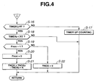
- the rich spike action time "RT” is read or used in both a judgement (viz., step S-16 of Fig. 4) as to whether the rich spike action has finished or not and a judgement (viz., step S-18 of Fig. 4) as to whether the existing condition takes place just after the rich spike action has finished or not, and the enriching rate "RICH” is read or used in an arithmetic routine that calculates a pulse width "Ti" for a fuel injection.
- step S-8 If NO at step S-8, that is, when thereafter the engine operation is kept carried out on the stoichiometric air/fuel ratio range (or rich air/fuel ratio range), the operation flow goes to step S-16 of the flowchart of Fig. 4.
- the elapsed time "TIMER” measured by the timer is compared with the rich spike action time "RT" stored in the memory.
- the elapsed time "TIMER” is smaller than the rich spike action time "RT”, and thus, in such stage, the step S-16 issues NO answer and thus the operation flow goes to step S-17.
- step S-17 up-counting of the timer is carried out.
- step S-16 issues YES answer and thus the operation flow goes to step S-18.
- step S-18 a last value "TIMERz” of the counted time is compared with the rich spike action time "RT”. If YES, that is, "TIMERz ⁇ RT" is established, the operation flow goes to step S-19 considering that the existing condition takes place just after the counted time has exceeded the rich spike action time "RT”.
- step S-19 the flag "Fnox" is checked.
- the purpose of this step S-19 is the same as that of the above-mentioned step S-10.
- the amount "TNOXz x K" of NOx released by the current rich spike action is obtained by subtracting the amount "TNOXz x K" of NOx released by the current rich spike action from the amount “TNOXz” of NOx that has been stored just before starting of the rich spike action. Since the rich spike action for releasing "K%" of the amount TNOXz" of NOx that has been stored by the catalyst just before starting of the rich spike action must be done, the value "TNOXz x K" corresponds to the amount of NOx that is presently released.
- Fig. 6 there is shown a flowchart that shows programmed operation steps for calculating the pulse width "Ti" for fuel injection applied to the fuel injector 16 (see Fig. 1). It is to be noted that routine of these steps is executed every given period, for example every 10ms independently of the above-mentioned routines of Figs. 3 and 4.
- the basic pulse width "Tp" represents the amount of fuel needed for one rotation of the engine 10. By practically using the pulse width "Tp", a mixture of stoichiometric air/fuel ratio is obtained.
- step S-35 by looking up a map of Fig. 7 showing a relation between the engine speed "Ne” and the intake air flow rate "Qa", the target equivalent ratio "TFBYA" is obtained. That is, as shown by the map of Fig. 7, in the three engine operation ranges, there are contained different values of the ratio "TFBYA".
- the range occupied by "TFBYA ⁇ 1" is a range (viz., lean air/fuel ratio range) wherein the target air/fuel ratio is a lean air/fuel ratio
- the range occupied by "TFBYA > 1" is a range (viz., rich air/fuel ratio range) wherein the target air/fuel ratio is a rich air/fuel ratio.
- step S-34 the enriching rate "RICH” stored in the memory is set as the target equivalent ratio "TFBYA".
- the pulse width "Ti" calculated in the above-mentioned manner is stored in the memory of the control unit 18 and practically read or used in a fuel injection execution routine that is executed in synchronization with the rotation of the engine 10. In a sequential fuel injection, each fuel injector 16 is opened for the period of the pulse width "Ti" once for each rotation of the engine 10.
- the NOx-releasing rate "K” is calculated using the weighted means “QaH” of the intake air flow rate "Qa” that represents the historical data of engine load. Based on this NOx-releasing rate "K”, the reduction correction values "R1" and “RT1” for a rich spike action are so calculated that the rich spike action would induce releasement of K% of stored NOx from the catalyst. Based on these correction values "R1” and “RT1”, the basic controlled values "R0" and “RT0" for the rich spike action are corrected to calculate the enriching rate "RICH” and the rich spike action time "RT”. By using these controlled values, the rich spike action is carried out pactically.
- the rich spike action that takes place when, under engine operation on a lean air/fuel ratio range, NOx stored by the catalyst increases to a predetermined amount can bring about both recovering of NOx-storing ability of the catalyst and improvement in fuel consumption.
- the judgement as to whether a rich spike action becomes needed or not is carried out in the following-manner. That is, by multiply the amount ( ⁇ NOXeo) of NOx exhausted from the engine to the exhaust passage at each calculation interval by the NOx-storing rate, the amount " ⁇ NOX” of NOx stored at each calculation interval is obtained, and by integrating the amount “ ⁇ NOX” at each calculation interval, the amount “TNOX” of NOx presently left in the catalyst is estimated, and then by comparing the amount "TNOX” with the judgement reference value "NOXth", the judgement is made.
Landscapes
- Engineering & Computer Science (AREA)
- Chemical & Material Sciences (AREA)
- Combustion & Propulsion (AREA)
- Mechanical Engineering (AREA)
- General Engineering & Computer Science (AREA)
- Exhaust Gas After Treatment (AREA)
- Electrical Control Of Air Or Fuel Supplied To Internal-Combustion Engine (AREA)
Abstract
Description
- The present invention relates in general to exhaust gas purifying systems of an internal combustion engine and more particularly to exhaust gas purifying systems of a type that has a NOx-storable type three-way catalytic converter installed in an exhaust passage extending from the engine. More specifically, the present invention is concerned with the exhaust gas purifying systems of a type that needs the internal combustion engine to operate on a leaner air/fuel mixture.
- Hitherto, a so-called NOx-storable type three-way catalytic converter has been proposed, that has such a performance that when the exhaust gas from the engine shows a higher air/fuel ratio (viz., leaner mixture), the converter (more specifically, the catalyst of the converter) traps and stores NOx in the exhaust gas, while when the exhaust gas shows a stoichiometric or lower air/fuel ratio (viz., richer mixture), the catalyst releases NOx allowing reduction of the same in the exhaust gas with the aid of HC and CO contained in the exhaust gas. That is, the released NOx is purified by using unburned HC and CO as reducing agents.
- As has been mentioned hereinabove, under engine operation on a lean air/fuel ratio range, the catalyst of the NOx-storable catalyst converter traps and stores NOx thereby to reduce NOx in the exhaust gas actually disposed to the open air. However, when the amount of NOx stored by the catalyst comes up to a maximum storing capacity thereof, NOx in the exhaust gas from the engine can not be trapped and stored by the catalyst any longer. Thus, in this condition, the NOx in the exhaust gas would be discharged to the open air directly without being trapped by the converter.
- For dealing with this undesirable phenomenon, a so-called "rich spike control" has been proposed wherein upon occurrence of the maximum storing of NOx by the catalyst of the converter, the target air/fuel ratio of the mixture fed to the engine is temporarily changed to a stoichiometric ratio or lower ratio (viz., richer mixture) to force the catalyst to release stored NOx for recovering the NOx-storing ability of the catalyst.
- In the exhaust gas purifying systems disclosed in Japanese Patent First Provisional Publications 6-10725 and 6-294319, there is employed a NOx absorbent in the exhaust passage. That is, when the air/fuel ratio of the exhaust gas is higher than the stoichiometric ratio, the NOx absorbent absorbs NOx in the exhaust gas, and when the oxygen concentration in the exhaust gas towers to a certain level, the NOx absorbent releases the absorbed NOx therefrom. In these disclosed systems, the temperature of the catalyst of the converter and/or the flow rate of exhaust gas led to the converter is used as a parameter of controlling operation of the system.
- In the exhaust gas purifying systems mentioned above, the rich spike action is conducted on the assumption that entirety of NOx stored by the catalyst of the converter should be released and reduced. This means that the rich spike action is inevitably carried out irrespective of the engine load at the time when the rich spike action becomes needed under the engine operation on a lean air/fuel ratio range. In view of this control, there is much room for improving fuel consumption of the engine in the systems of the references.
- That is, one of the performance characteristics of the NOx-storable catalyst is the "NOx-storing rate" that is defined by dividing the amount of NOx stored by the catalyst per unit time by the amount of NOx led into the catalyst per unit time. Usually, the NOx-storing rate lowers as stored amount of NOx increases. Furthermore, when the NOx-storing rate is kept high, the NOx storing action by the catalyst is carried out irrespective of the amount of NOx left in the catalyst.
- Experiments by the inventors have revealed that the phenomenon wherein the NOx-storing rate lowers as the amount of NOx left in the catalyst increases shows a less tendency in a lower load engine operation on the lean air/fuel ratio range than in a higher load engine operation. This means that since, in the lower load engine operation on a lean air/fuel ratio region, a higher NOx-storing rate can be kept even when the amount of NOx stored by the catalyst is marked, there is no need of releasing and reducing the entirety of NOx stored by the catalyst at the time of rich spike action. In other words, the amount of fuel used for the rich spike action can be reduced by controlling the rich spike action to reduce only a part of NOx stored by the catalyst of the converter.
- It is therefore an object of the present invention to provide an exhaust gas purifying system wherein when the engine operation shows a lower load when a rich spike action becomes needed under operation on a lean air/fuel ratio range, a so-called "partial rich spike action" is carried out for releasing and reducing a part of NOx stored by the catalyst, thereby to bring about both recovering of the NOx-storing ability of the catalyst and saving of fuel used for the rich spike action.
- According to a first aspect of the present invention, there is provided an exhaust gas purifying system of an engine. The system comprises a catalyst installed in an exhaust passage of the engine, the catalyst being of a type that traps and stores NOx in the exhaust gas when the air/fuel ratio of the exhaust gas is higher than the stoichiometric ratio and reduces stored NOx with the aid of reducing components in the exhaust gas when the air/fuel ratio of the exhaust gas is equal to or lower than the stoichiometric ratio; a detector that detects operation load of the engine; and a control unit including a microprocessor that is programmed to carry out calculating the amount of stored NOx when the air/fuel ratio of the exhaust gas is higher than the stoichiometric ratio; judging whether or not the catalyst needs recovering of the NOx-storing ability thereof in accordance with the calculated amount of the stored NOx; determining the amount of NOx to be reduced in accordance with the engine load detected by the-detector; and carrying out a catalyst recovering control when the need of recovering the NOx-storing ability is judged, the catalyst recovering control being a control to keep the air/fuel ratio of the exhaust gas at a predetermined lower ratio for a predetermined period, thereby to reduce the determined amount of NOx.
- According to a second aspect of the present invention, there is provided an exhaust gas purifying method carried out in a system that includes an engine and a catalyst installed in an exhaust passage of the engine, the catalyst being of a type that traps and stores NOx in the exhaust gas when the air/fuel ratio of the exhaust gas is higher than the stoichiometric ratio and reduces the stored NOx with the aid of reducing components in the exhaust gas when the air/fuel ratio of the exhaust gas is equal to or lower than the stoichiometric ratio. The method comprises detecting operation load of the engine; calculating the amount of stored NOx when the air/fuel ratio of the exhaust gas is higher than the stoichiometric ratio; judging whether or not the catalyst needs recovering of the NOx-storing ability thereof in accordance with the calculated amount of the stored NOx; determining the amount of NOx to be reduced in accordance with the engine load; and carrying out a catalyst recovering control when the need of recovering said NOx-storing ability is judged, the catalyst recovering control being a control to keep the air/fuel ratio of the exhaust gas at a predetermined lower ratio for a predetermined period, thereby to reduce the determined amount of NOx.
-
- Fig. 1 is a schematic view of an internal combustion engine to which the present invention is practically applied;
- Fig. 2 is a time chart depicting operation of the present invention;
- Figs. 3 and 4 are flowcharts showing programmed operation steps executed in a control unit for carrying out a rich spike action employed in the present invention;
- Fig. 5 is a graph showing a relationship between the amount of NOx stored and the NOx-storing rate with respect to an engine load;
- Fig. 6 is a flowchart showing programmed operation steps executed in the control unit for calculating a pulse width for fuel injection; and
- Fig. 7 is a graph showing the characteristic of a target equivalent ratio determined in accordance with an engine operating condition.
-
- In Fig. 1, there is schematically shown an
internal combustion engine 10 to which an exhaust gas purifying system of the present invention is practically applied. - Designated by
numeral 12 is an induction passage that leads to intake ports of theengine 10. Athrottle device 14 is mounted in theinduction passage 12 to feed each combustion chamber of theengine 10 with a metered air. Thethrottle device 14 is powered by athrottle actuator 14A such as a DC motor or the like. Afuel injector 16 is exposed to each combustion chamber of theengine 10. That is, the engine shown in Fig. 1 is of a gasoline direct injection (viz., GDI) type. - For operating the
fuel injector 16 in such a manner that the combustion chamber receives a mixture of desired air/fuel ratio, an electronic control unit (ECU) 18 feeds theinjector 16 with an instruction signal in accordance with operating conditions of the associated motor vehicle and theengine 10. Each combustion chamber has anignition plug 20. Although theengine 10 shown is of the gasoline direct injection type, a normal type engine wherein the fuel injector is exposed to theinduction passage 12 may be used in the present invention. - To the
electronic control unit 18, there are fed various information signals which are a reference position signal and a unit angle signal which are issued from acrank angle sensor 22, an intake air flow rate signal which is issued from an air flow meter 24 (viz., engine load detecting means), an accelerator open degree signal which is issued from anaccelerator sensor 26, an engine cooling water temperature signal which is issued from an engine coolingwater temperature sensor 28, a gear position signal which is issued from a gear position sensor (not shown) of an associated transmission and a vehicle speed signal which is issued from a vehicle speed sensor (not shown). By processing these information signals, thecontrol unit 18 controls theengine 10 to operate on a mixture of lean air/fuel ratio (viz., higher air/fuel ratio) when the engine load is not so high, and controls theengine 10 to operate on a mixture of stoichiometric air/fuel ratio or rich ratio when the engine load is relatively high. - As shown, a NOx-storable
catalytic converter 32 is installed on anexhaust passage 30. The catalyst of the NOx-storablecatalytic converter 32 has such a performance that when the exhaust gas from theengine 10 shows a leaner air/fuel ratio (viz., higher ratio than stoichiometric), the catalyst traps and stores NOx in the exhaust gas, while when the exhaust gas shows a stoichiometric or richer air/fuel ratio (viz., lower ratio than stoichiometric), the catalyst releases NOx and purifies the same with the aid of reducing agents, such as HC and CO contained in the exhaust gas. Theconverter 32 comprises a honeycomb carrier coated with aluminum (Pt), a base catalyst of a noble metal such as platinum (Pt), palladium (PD), rhodium (rh) or the like carried on the aluminum-coated surface of the honeycomb carrier and an extra substance such as barium (Ba) (alkali earth metal), cesium (Cs) (alkali metal) or the like added to the base catalyst. - For the reason as has been described hereinabove, in usage of the exhaust gas purifying system, it is necessary to carry out a rich spike action for recovering the NOx-storing ability of the catalyst of the
converter 32. - The rich spike action will be explained with reference to the time chart of Fig. 2. This time chart shows a case wherein, as is indicated by "LEAN-1", first a higher engine, load operation is carried out on a lean air/fuel ratio range, then, due to change of operation condition of the vehicle, as is indicated by "LEAN-2" and "LEAN-3", a lower engine load operation is carried out on the lean air/fuel ratio range.
- Under operation of the
engine 10, the NOx-storing ability of the catalyst of theconverter 32 lowers with increase of NOx stored by the same, and thus, the amount of NOx released from the catalyst increases gradually with passage of time. Thus, for keeping the amount of NOx actually discharged to the open air below a predetermined reference level in the lean air/fuel ratio range of the engine, it is necessary to carry out the rich spike action for recovering the NOx-storing ability of the catalyst of theconverter 32 at the time when the amount of NOx stored by the catalyst increases to a given level. This given level is so determined that the amount of NOx actually discharged to the open air is kept below the predetermined reference level during a lean combustion operation period from one rich spike action to a subsequent rich spike action. - When the "NOx-storing rate" is defined by dividing the amount of NOx stored by the catalyst per unit time by the amount of NOx led into the catalyst per unit time, an important fact as shown in the graph of Fig. 5 becomes revealed. That is, as is seen from this graph, in the lean air/fuel ratio range, the lowering tendency of the NOx-storing rate relative to increase of the amount of NOx stored by the catalyst shows a difference between a high load operation and a low and medium load operation. That is, regarding the lowering tendency of the NOx-storing rate, the low and medium load operation shows a less degree than the high load operation. This fact has been revealed by the experiments made by the inventors.
- From this revealed fact, the following consideration will be provided. That is, as is shown by a phantom line of the air/fuel ratio part of the time chart of Fig. 2, when the rich spike action takes place in the lean air/fuel ratio range irrespective of engine load at times "t1" and "t2" when the amount of NOx stored by the catalyst increases to a predetermined amount in the lean air/fuel ratio range and continues (viz., RICH-1 and RICH-2) until the time when NOx stored by the catalyst is entirely released and reduced, the tendency of lowering the NOx-storing rate in the low load operation (viz., LEAN-3) on the lean air/fuel ratio range becomes smaller than that of the NOx-storing rate of the high load operation (viz., LEAN-1) on the lean air/fuel ratio range. Accordingly, as is seen from the NOx-storing rate part of Fig. 2, the averaged NOx-storing rate (indicated by two-dot chain line) in the low load operation on the lean air/fuel ratio range becomes higher than that (indicated by a broken line) of the high load operation on the lean air/fuel ratio range. In other words, if the averaged NOx-storing rate in the high load operation on lean air/fuel ratio range shows an appropriate value, the averaged NOx-storing rate in the low load operation on the lean air/fuel ratio range inevitably shows a very high value, and thus, in a low load operation of the engine on the lean air/fuel ratio, range, a satisfied NOx-storing rate can be kept by releasing only a part of stored NOx from the catalyst. Of course, the amount of fuel needed to effect such a "partial rich spike action" for releasing and reducing a part of stored NOx is smaller than that need to effect a full rich spike action for releasing and reducing the entirety of stored NOx. Accordingly, it becomes known that operation of the engine with the rich spike action applied to a part of stored NOx brings about an improved fuel consumption of the engine.
- In view of the above, the
control unit 18 is so arranged and programmed that when, under the low load operation on the lean air/fuel ratio range, the engine load shows a lower level at times "t2" and "t3" when stored NOx has increased to the predetermined amount, a partial rich spike action for releasing and reducing a part of stored NOx is carried out as is indicated by RICH-2' and RITC-3' in Fig. 2. - This rich spike action will be described in detail in the following with reference to the flowcharts shown in Figs. 3 and 4. It is to be noted that the routine shown by these flowcharts is carried out every given period, for example, every 10ms.
- In the flowchart of Fig. 3, at step S-1, the catalyst temperature "Tcat", engine speed "Ne" and intake air flow rate "Qa" are read. The catalyst temperature "Tcat" is obtained by effecting an A/D (viz., analogue/digital) conversion to an output issued from a temperature sensor 34 (see Fig. 1) fixed to the
converter 32. The engine speed "Ne" is calculated from the interval at which the reference position signal is issued from thecrank angle sensor 22. In case of four-cylinder engines, such reference position signal is issued every 180 degrees. - Referring back to Fig. 3, at step S-2, a target equivalent ratio "TFBYA" is compared with 1 (one). It is to be noted that the target equivalent ratio is provided by dividing the stoichiometric air/fuel ratio by a target air/fuel ratio. Thus, when the target air/fuel ratio is the stoichiometric one, the target equivalent ratio "TFBYA" is 1 (one). When the target air/fuel ratio is greater than the stoichiometric one, that is, when the target air/fuel ratio shows a leaner condition, the target equivalent ratio "TFBYA" shows a value smaller than 1 (one), while when the target air/fuel ratio is smaller than the stoichiometric one, that is, when the target air/fuel ratio shows a richer condition, the target equivalent ratio "TFBYA" shows a value greater than 1 (one).
- As is seen from the graph of Fig. 7, the target equivalent ratio "TFBYA" is looked up from a map that carries the engine speed "Ne" and the intake air flow rate "Qa" as parameters.
- Referring back to the flowchart of Fig. 3, if at step S-2 the target equivalent ratio "TFBYA" is smaller than 1 (one), that is, when leaner air/fuel condition is detected, the operation flow goes to steps S-3, S-4, S-5, S-6 and S-7.
- As will become apparent as the description proceeds, at the steps S-3, S-4, S-5 and S-6, the stored amount of NOx in a lean air/fuel ratio range is calculated and a judgement is carried out as to whether stored NOx has increased to a predetermined amount or not, that is, whether a rich spike action has become needed or not.
- That is, at step S-3, a weighted mean "QaH" of the intake air flow rate "Qa" is calculated by using the following equation:
- k : coefficient of weighted mean
- QaHz : last value of QaH
-
- The weighted means "QaH" represents the historical data of the engine load. That is, when the weighted means "QaH" shows a small value, it represents that a low load operation on a lean air/fuel ratio range has been continuously carried out and thus there is a high possibility of continuing such low load operation on the lean air/fuel ratio range from now on.
- If desired, in place of the above-mentioned method, the following method may be used for obtaining the value "QaH". That is, the data on the intake air flow rate "Qa" obtained at each calculation of the routine is memorized using time series and by practically applying a statistic treatment to the memorized data, tendency of transition of the engine load is obtained to predict coming engine load on average, and the predicted engine load is used as the value "QaH". Furthermore, in a simpler way, only the latest value "Qa" may be memorized as the value "QaH".
- At step S-4, the amount "TNOX" of NOx presently left on the catalyst is calculated by using the following equation:
- TNOXz : last value of TNOX
- ΔNOX : amount of NOx stored at each calculation interval (viz., at each 10ms.)
-
- That is, by adding the amount "ΔNOX" of NOx stored at each calculation interval of the routine to the value "TMOXz" that is the amount of NOx that has been calculated at the last operation step flow, the amount "TNOX" of NOx presently stored is obtained.
- The amount "ΔNOX" of NOx stored at each calculation interval is calculated from the following equation:
- ΔNOXeo: amount of NOx exhausted by the engine to the exhaust passage at each calculation interval;
- NOx-storing rate: value obtained by dividing the amount of NOx stored per unit time by the amount of NOx fed to the catalyst per unit time.
-
- It is to be noted that the value "ΔNOXeo" can be estimated from parameters of engine operation condition, such as, engine speed "Ne", intake air flow rate "Qa", target equivalent ratio "TFBYA" and the like. This estimation method is well known.
- The NOx-storing rate is obtained by dividing the amount of NOx stored by the catalyst per unit time by the amount of NOx fed to the catalyst per unit time. In practice, the NOx-storing rate is calculated from the value "TNOXz" (viz., the last value of "TNOX") and the engine load in the lean air/fuel ratio range (for example, intake air flow rate "Qa") with reference to the map of Fig. 5. As has been mentioned hereinabove and as is seen from the map of Fig. 5, in the lean air/fuel ratio range, the NOx-storing rate shows a higher value in the low load operation than in the high load operation. This fact has been revealed by the inventors. Although the map of Fig. 5 shows only the values for two load conditions, that is, the high load operation and low load operation, more than two load conditions may be used for improving the precision of the calculation.
- The NOx-storing rate is affected by the catalyst temperature "Tcat" and thus the temperature "Tcat" may be used as a parameter of the NOx-storing rate. In this case, the NOx-storing rate shows such a temperature characteristic that when the load is kept constant the NOx-storing rate shows a maximum value at a predetermined temperature of the catalyst. That is, the NOx-storing rate tends to lower when the temperature of the catalyst becomes higher or lower than the predetermined temperature.
- Referring back to the flowchart of Fig. 3, at step S-5, a judgment reference value "NOXth" (viz., predetermined value) for a subsequent judging step is calculated, and at step S-6, the reference value "NOXth" is compared with the amount "TNOX" of NOx presently stored.
- The judgement reference value "NOXth" is a value affected by the catalyst temperature "Tcat". Thus, the value "NOXth" is calculated in accordance with the catalyst temperature "Tcat". That is, the judgement reference value "NOXth" has such a temperature characteristic that it shows the maximum value when the catalyst temperature "Tcat" is at the predetermined temperature and lowers when the catalyst temperature "Tcat" becomes higher or lower than the predetermined temperature.
- The temperature characteristic of the judgment reference value "NOXth" changes depending on the type of the catalyst. If the affection of the catalyst temperature is negligibly small, the judgement reference value "NOXth" can be a fixed value.
- If YES at step S-6, that is, when the value "TNOX" is greater than the reference value "NOXth", the operation flow goes to step S-7 realizing the necessity of a rich spike action. That is, at step S-7, a flag for rich spike action is raised, that is, "Fnox =1" is established and stored in the memory of the control unit 18 (see Fig. 1). While, if NO at step S-6, that is, when the value "TNOX" is smaller than the reference value "NOXth", the operation flow goes to RETURN realizing non-necessity of the rich spike action. That is, "Fnox = 0" is kept. It is to be noted that upon starting of the
engine 10, the flag "Fnox" is set to 0 (zero), that is, "Fnox = 0" is established. - As will be described hereinafter at the section of Fig. 6, the flag "Fnox" is read or used also in an arithmetic routine that calculates a pulse width "Ti" for a fuel injection. Accordingly, in the routine, upon setting of 1 (one) of the flag "Fnox", the rich spike action starts causing the target equivalent ratio "TFBYA" to be greater than 1. Thus, in the routine of Fig. 3, just after the flag "Fnox" becomes 1 (one), the operation flow goes from step S-2 to step S-8.
- While, if, at step S-2, "TFBYA ≥ 1" is established, the operation flow goes from step S-2 to step S-8 to judge whether or not the target equivalent ratio "TFBYA" has changed from a value smaller than 1 (one) to a value larger than 1 (one) (viz., whether or not the engine operation has changed from a lean air/fuel ratio range to a stoichiometric range or to a richer range) or to judge whether the flag "Fnox" has changed from 0 (zero) to 1 (one) or not.
- It is to be noted that the judgement as to whether or not the "TFBYA" has changed from under 1 to over 1 can be known when looking up a "TFBYAz" that is the last target equivalent ratio. If the last target equivalent ratio "TFBYAz" is smaller than 1 (one), it becomes known that the engine operation has changed from the lean air/fuel ratio range to the stoichiometric range or to the rich range. Thus, in this case, the operation flow goes to step S-9. At this step S-9, a timer for measuring an elapsed time from the time when the engine operation on the stoichiometric (or rich) air/fuel ratio range has started is reset to. 0 (zero), that is, "TIMER = 0" is established.
- The judgement as to whether the flag "Fnox" has changed from 0 to 1 can be known when looking up the last value of the flag "Fnox". If the last value of the flag is 0 (zero), it becomes known that in the current flow, the flag "Fnox" has changed from 0 (zero) to 1 (one). Thus, also in this case, the operation flow goes to step S-9 to reset the timer for measuring an elapsed time from the time when the flag "Fnox" has changed from 0 (zero) to 1 (one).
- Then, the operation flow goes to step S-10. At this step, a judgement is carried out as to whether the flag "Fnox" is 1 (one) or not. If NO, that is, when the flag "Fnox" is 0 (zero), that is, when, due to change of operation condition, the engine operation has changed from the lean air/fuel ratio range to the stoichiometric range or to the rich range, the operation flow goes to step S-15. At this step, a time "RTbase" needed for releasing and reducing the entirety of NOx left in the catalyst by carrying out the engine operation on a stoichiometric air/fuel mixture is set as a rich spike action time "RT". It is to be noted that the stored amount of NOx is about the same as the amount corresponding to the judgement reference value "NOXth". Then, the operation flow goes to "RETURN".
- Thus, when the time "RTbase" passes after changing of the engine operation from the lean air/fuel ratio range to the stoichiometric range or to the rich range, the entirety of NOx left in the catalyst is inevitably released and reduced.
- While, if YES at step S-10, that is, when the flag "Fnox" is 1 (one), that is, when the engine operation on the lean air/fuel ratio range has been kept, the operation flow goes to steps S-11, S-12, S-13 and S-14 to carry out a rich spike action for enforcedly effecting the engine operation on the rich air/fuel ratio range and thus releasing and reducing a predetermined amount of NOx stored by the catalyst. It is to be noted that the steps S-11, S-12, S-13 and S-14 are steps for calculating controlled values (viz., an enriching rate "RICH" and the above-mentioned rich spike action time "RT") used for a rich spike action which will be described in the following.
- It is to be noted that with increase of the enriching rate "RICH", the amount of NOx released from the catalyst per unit time increases, and with increase of the rich spike action time "RT", the total amount of NOx released from the catalyst increases.
- The amount of NOx released from the catalyst can be controlled by allowing one of the enriching rate "RICH" and the rich spike action time "RT" to have a fixed value and allowing the other to have a variable value. However, if the catalyst used is of a type that releases stored NOx in accordance with lowering of oxygen concentration in the exhaust gas fed thereto, it is necessary to make such a control that the amount of reducing components (viz., HC and CO) fed to the catalyst per unit time is constantly greater than that of NOx released from the catalyst per unit time. The amount of the reducing components fed to the catalyst per unit time is proportional to a product of the enriching rate "RICH" and the exhaust gas flow rate (which is substantially equal to the intake air flow rate "Qa"). Thus, in case of using the above-mentioned type catalyst, it is desirable to allow the enriching rate "RICH" to have a fixed value that constantly assures a sufficient feeding of the reducing components to the catalyst per unit time and to allow the rich spike action time "RT" to have a variable value.
- Referring back to the flowchart of Fig. 3, at step S-11, in accordance with the existing intake air flow rate "Qa" and the existing stored amount "TNOX" of NOx, basic controlled values "R0" and "RT0" used for a rich spike action are calculated. It is to be noted that the basic controlled value "R0" is for the enriching rate "RUCH" and has a unit corresponding to an equivalent ratio, and the basic controlled value "RT0" is for the rich spike action time "RT" and has a unit corresponding to a time. More specifically, the basic controlled value "R0" is a value of enriching rate (R0 ≥ 1) that assures feeding of sufficient amount of reducing components (viz., HC and CO) to the catalyst under the existing intake air flow rate "Qa". This means that the amount of reducing components fed to the catalyst per unit time is greater than that of NOx released from the catalyst per unit time. The basic controlled value "RT0" is the time (RT0 > 0) when the total amount of NOx released from the catalyst becomes greater than that of NOx presently stored by the catalyst. Accordingly, if, during the time of the basic controlled value "RT0", the rich spike action is carried-out with the enriching rate "R0", the entirety of NOx stored by the catalyst is released and reduced like in the conventional exhaust gas purifying system.
- Just after change of the flag "Fnox" from 0 (zero) to 1 (one), the amount "TNOX" of stored NOx shows a value generally equal to the judgment reference value "NOXth". Thus, in place of using the "TNOX", the judgement reference value "NOXth" may be used. In case wherein the judgment reference value "NOXth" is used as a single fixed value, the basic controlled values "R0" and "RT0" are calculated from only the intake air flow rate "Qa".
- At step S-12, a so-called NOx-releasing rate "K" is set. That is, with the aid of the weighted means "QaH" of the intake air flow rate "Qa", the NOx-releasing rate "K" represents how much percentage of stored NOx has been released and reduced just before starting of the rich spike action. For example, "K = 50%" means that 50% of NOx stored by the catalyst is released and reduced, and "K = 100%" means that all of NOx stored by the catalyst is released and reduced.
- With decrease of the weighted means "QaH" of the intake air flow rate "Qa", that is, with increase of possibility of continuing the low load operation on the lean air/fuel ratio range, the NOx-releasing rate "K" is reduced. With this, in place of reducing the amount of NOx released from the catalyst, fuel increase induced by the rich spike action is controlled. That is, when the low load operation is being kept, sufficient NOx-storing rate of the catalyst is assured without releasing and reducing the entirety of stored NOx.
- In case wherein the weighted means "QaH" of the intake air flow rate "Qa" is large, that is, in case wherein a possibility of continuing the high load operation on the lean air/fuel ratio range is high, it becomes necessary to release and reduce the entirety of stored NOx in order to obtain a sufficient NOx-storing rate of the catalyst. Thus, in this case, the NOx-releasing rate "K" is set to about 100%.
- It is desirable that the weighted means "QaH" of the intake air flow rate "Qa" indicates an averaged engine load condition that will continue on the lean air/fuel ratio range to a time when a subsequent rich spike action takes place. Accordingly, usage of the weighted means "QaH" is preferable rather than usage of the intake air flow rate "Qa". Furthermore, it is much desirable to use a predicted value as the value "QaH", that is provided by practically applying a statistic treatment to memorized data. Furthermore, if any parameters having a correlation with the engine load (for example, the exhaust gas flow rate) on the lean air/fuel ratio range are provided, the throttle opening degree, the intake vacuum, a basic pulse width "Tp" for fuel injection and their weighted means may be used in place of the values "Qa" and "QaH".
- Referring back to the flowchart of Fig. 3, at step S-13, correction values "R1" and "RT1" for the basic controlled values "R0" and "RT0" are calculated. That is, if the above-mentioned basic controlled values "R0" and "RT0" are subjected to a reduction correction (viz., correction by reducing the enriching rate or correction by shortening the rich spike action time), the amount of NOx released from the catalyst is decreased. Thus, the correction values "R1" (0 < R1 ≤ 1) and "RT1" (0 < RT1 ≤ 1) are so calculated that the amount of NOx released from the catalyst shows "K%" of the amount of NOx stored by the catalyst. Then at step S-14, using the correction values "R1" and "RT1" and the basic controlled values "R0" and "RT0", the enriching rate "RICH" and the rich spike action time "RT" are calculated by using the following equations:
- That is, the values obtained by subjecting the basic controlled values "R0" and "RT0" to the reduction correction are used as the enriching rate "RICH" and the rich spike action time "RT". Then, the operation flow goes to "RETURN" as shown. Of course, even though the basic controlled value "R0" of the enriching rate is corrected by using the correction value "R1", the NOx-releasing rate "K" is so set as to make the corrected enriching rate "RICH" greater than 1 (one).
- The enriching rate "RICH" and the rich spike action time "RT" obtained in the above-mentioned manner are stored in the memory (RAM) of the control unit 18 (see Fig. 1). As will be described in the following, the rich spike action time "RT" is read or used in both a judgement (viz., step S-16 of Fig. 4) as to whether the rich spike action has finished or not and a judgement (viz., step S-18 of Fig. 4) as to whether the existing condition takes place just after the rich spike action has finished or not, and the enriching rate "RICH" is read or used in an arithmetic routine that calculates a pulse width "Ti" for a fuel injection.
- If NO at step S-8, that is, when thereafter the engine operation is kept carried out on the stoichiometric air/fuel ratio range (or rich air/fuel ratio range), the operation flow goes to step S-16 of the flowchart of Fig. 4. At this step, the elapsed time "TIMER" measured by the timer is compared with the rich spike action time "RT" stored in the memory. At an initial stage of the time measuring by the timer, the elapsed time "TIMER" is smaller than the rich spike action time "RT", and thus, in such stage, the step S-16 issues NO answer and thus the operation flow goes to step S-17. At this step S-17, up-counting of the timer is carried out.
- When, after repeated up-counting by the timer, the elapsed time "TIMER" becomes equal to or greater than the rich spike action time "RT", the step S-16 issues YES answer and thus the operation flow goes to step S-18. At this step S-18, a last value "TIMERz" of the counted time is compared with the rich spike action time "RT". If YES, that is, "TIMERz < RT" is established, the operation flow goes to step S-19 considering that the existing condition takes place just after the counted time has exceeded the rich spike action time "RT". At step S-19, the flag "Fnox" is checked. The purpose of this step S-19 is the same as that of the above-mentioned step S-10. That is, when "Fnox = 0" is established, judgement is so made that a time "RTbase" has passed from the time when the engine operation has changed from the lean air/fuel ratio range to the stoichiometric range or to the rich range. In this case, the entirety of stored NOx is released and reduced, and thus the operation flow goes to step S-22 to reset the value of "TNOX" to 0 (zero).
- While, if YES at step S-19, that is, "Fnox = 1" is established, judgement is so made that a time "RT0 x RT1" (=RT) has passed from the time when a rich spike action started for enforcedly making the air/fuel mixture rich for the purpose of releasing and reducing a predetermined amount of NOx stored by the catalyst. Thus, in this case, the operation flow goes to step S-20 to reset the flag "Fnox" to 0 (zero).
- Then, the operation flow goes to step S-21. At this step, the amount "TNOX" of NOx presently stored by the catalyst is calculated by using the following equation:
- That is, by subtracting the amount "TNOXz x K" of NOx released by the current rich spike action from the amount "TNOXz" of NOx that has been stored just before starting of the rich spike action, the amount "TNOX" of NOx presently stored by the catalyst is obtained. Since the rich spike action for releasing "K%" of the amount TNOXz" of NOx that has been stored by the catalyst just before starting of the rich spike action must be done, the value "TNOXz x K" corresponds to the amount of NOx that is presently released.
- Referring to Fig. 6, there is shown a flowchart that shows programmed operation steps for calculating the pulse width "Ti" for fuel injection applied to the fuel injector 16 (see Fig. 1). It is to be noted that routine of these steps is executed every given period, for example every 10ms independently of the above-mentioned routines of Figs. 3 and 4.
- At step S-31, the engine speed "Ne" and the intake air flow rate "Qa" are read. Then, at step S-32, the basic pulse width "Tp" is calculated by using the following equation:
- K2 : constant
-
- The basic pulse width "Tp" represents the amount of fuel needed for one rotation of the
engine 10. By practically using the pulse width "Tp", a mixture of stoichiometric air/fuel ratio is obtained. - At step S-33, the flag "Fnox" stored in the memory is checked. If "Fnox = 0" is established, the operation flow goes to step S-35 because there is no need of effecting the rich spike action. At this step S-35, by looking up a map of Fig. 7 showing a relation between the engine speed "Ne" and the intake air flow rate "Qa", the target equivalent ratio "TFBYA" is obtained. That is, as shown by the map of Fig. 7, in the three engine operation ranges, there are contained different values of the ratio "TFBYA". The range occupied by "TFBYA = 1" is a range (viz., stoichiometric air/fuel ratio range) wherein the target air/fuel ratio is a stoichiometric ratio, the range occupied by "TFBYA < 1" is a range (viz., lean air/fuel ratio range) wherein the target air/fuel ratio is a lean air/fuel ratio, and the range occupied by "TFBYA > 1" is a range (viz., rich air/fuel ratio range) wherein the target air/fuel ratio is a rich air/fuel ratio.
- Referring back to the flowchart of Fig. 6, if YES at step S-33, that is, when "Fnox = 1" is established, the operation flow goes to step S-34 to carry out a rich spike action for enforcedly making the air/fuel mixture rich for the purpose of releasing and reducing a predetermined amount of NOx stored by the catalyst. For this operation, at step S-34, the enriching rate "RICH" stored in the memory is set as the target equivalent ratio "TFBYA". In this case, the target equivalent ratio "TFBYA" (= RICH) shows a value equal to or greater than 1 (one), and thus, the engine operation is carried out on a stoichiometric air/fuel ratio range or on a richer air/fuel ratio range.
- At step S-36, the pulse width "Ti" for a sequential fuel injection is calculated by using the following equation:
- α: air/fuel ratio feedback correction factor
- Ts: invalid fuel injection by fuel injector
-
- When the target equivalent ratio "TFBYA" is not 1 (one), the value of "α" is fixed to 1.0.
- The pulse width "Ti" calculated in the above-mentioned manner is stored in the memory of the
control unit 18 and practically read or used in a fuel injection execution routine that is executed in synchronization with the rotation of theengine 10. In a sequential fuel injection, eachfuel injector 16 is opened for the period of the pulse width "Ti" once for each rotation of theengine 10. - In operation, when, under a low load operation on a lean air/fuel ratio range, the amount of NOx stored by the catalyst increases to a predetermined amount, the NOx-releasing rate "K" is calculated using the weighted means "QaH" of the intake air flow rate "Qa" that represents the historical data of engine load. Based on this NOx-releasing rate "K", the reduction correction values "R1" and "RT1" for a rich spike action are so calculated that the rich spike action would induce releasement of K% of stored NOx from the catalyst. Based on these correction values "R1" and "RT1", the basic controlled values "R0" and "RT0" for the rich spike action are corrected to calculate the enriching rate "RICH" and the rich spike action time "RT". By using these controlled values, the rich spike action is carried out pactically.
- The operation will be described with reference to the time chart of Fig. 2.
- At the time "t2" or "t3" that shows a low load engine operation taken when stored NOx has increased to the predetermined amount, a so-called "partial rich spike action" (see RICH-2' of RICH-3') is carried out that aims to release and reduce K% of NOx stored by the catalyst, not to release and reduce the entirety of stored NOx. That is, at that time "t2" or "t3", the NOx-releasing rate "K" is calculated to have a value smaller than 100%. Even though the averaged NOx-storing rate (see the two-dot chain line "X" of the "NOx STORING RATE" part of the time chart) taken in the low load operation (see LEAN-3') on the lean air/fuel ratio range after the partial rich spike action shows a value somewhat lower than that expected when a conventional rich spike action is carried out, it is easy to keep the averaged NOx-storing rate above an averaged NOx-storing rate (see the broken line "Y" of the "NOx STORING RATE" part of the time chart) that is taken in the high load operation on the lean air/fuel ratio range. Furthermore, because of need of only a partial releasement and reduction of stored NOx, the amount of fuel used for the rich spike action is greatly saved.
- That is, the rich spike action that takes place when, under engine operation on a lean air/fuel ratio range, NOx stored by the catalyst increases to a predetermined amount can bring about both recovering of NOx-storing ability of the catalyst and improvement in fuel consumption.
- Referring back to the time chart of Fig. 2, at the time "t1" that shows a high load engine operation taken when stored NOx has increased to the predetermined amount, a so-called "full rich spike action" (see RICH-1) is carried out that aims to release and reduce the entirety of stored NOx. That is, at the time "t1", the NOx-releasing rate "K" is calculated to have a value of about 100%.
- In the above-mentioned embodiment, the judgement as to whether a rich spike action becomes needed or not is carried out in the following-manner. That is, by multiply the amount (ΔNOXeo) of NOx exhausted from the engine to the exhaust passage at each calculation interval by the NOx-storing rate, the amount "ΔNOX" of NOx stored at each calculation interval is obtained, and by integrating the amount "ΔNOX" at each calculation interval, the amount "TNOX" of NOx presently left in the catalyst is estimated, and then by comparing the amount "TNOX" with the judgement reference value "NOXth", the judgement is made.
- However, if desired, for simplification, one of the following values may be used in place of the value "TNOX":
- 1. Integrated value "SumNe" of engine speed in an engine operation on lean air/fuel ratio range,
- 2. Integrated value "SumTh" of throttle opening degree in an engine operation on lean air/fuel ratio range, and
- 3. Integrated value "SumQa" of intake air flow rate in an engine operation on lean air/fuel ratio range.
-
- In using these values, when the value "SumNe", "SumTh" or "SumQa" exceeds a corresponding judgement reference value, the above-mentioned rich spike flag "Fnox" is turned to 1 (one).
- Although the invention has been described above with reference to the embodiment of the present invention, the invention is not limited to the embodiment described above. Various modifications and variations of the embodiment described above will occur to those skilled in the art, in light of the above teachings.
Claims (7)
- An exhaust gas purifying system of an engine, comprising:a catalyst installed in an exhaust passage of the engine, the catalyst being of a type that traps and stores NOx in the exhaust gas when the air/fuel ratio of the exhaust gas is higher than the stoichiometric ratio and reduces the stored NOx with the aid of reducing components in the exhaust gas when the air/fuel ratio of the exhaust gas is equal to or lower than the stoichiometric ratio;a detector that detects operation load of said engine; anda control unit including a microprocessor that is programmed to carry out:calculating the amount of the stored NOx when the air/fuel ratio of the exhaust gas is higher than the stoichiometric ratio;judging whether or not the catalyst needs recovering of the NOx-storing ability thereof in accordance with the calculated amount of the stored NOx;determining the amount of NOx to be reduced in accordance with the engine load detected by said detector; andcarrying out a catalyst recovering control when the need of recovering said NOx-storing ability is judged, said catalyst recovering control being a control to keep the air/fuel ratio of the exhaust gas at a predetermined lower ratio for a predetermined period, thereby to reduce the determined amount of NOx.
- An exhaust gas purifying system as claimed in Claim 1, in which said microprocessor is further programmed to determine both said predetermined period and said predetermined lower air/fuel ratio in accordance with the determined amount of NOx to be reduced.
- An exhaust gas purifying system as claimed in Claim 1, in which said microprocessor is further programmed to decrease the amount of NOx to be reduced as the engine load lowers.
- An exhaust gas purifying system as claimed in Claim 1, in which said microprocessor is further programmed to determine the amount of NOx to be reduced in accordance with the engine load that is detected when the need of recovering the NOx-storing ability of the catalyst is judged.
- An exhaust gas purifying system as claimed in Claim 1, in which said microprocessor is further programmed to determine the amount of NOx to be reduced in accordance with a historical data of the engine load that has been collected by said detector.
- An exhaust gas purifying system as claimed in Claim 1, in which said microprocessor is further programmed to judge the need of recovering the NOx-storing ability of the catalyst when the calculated amount of stored NOx increases to a predetermined amount.
- In a system including an engine and a catalyst installed in an exhaust passage of the engine, said catalyst being of a type that traps and stores NOx in the exhaust gas when the air/fuel ratio of the exhaust gas is higher than the stoichiometric ratio and reduces the stored NOx with the aid of reducing components in the exhaust gas when the air/fuel ratio of the exhaust gas is equal to or lower than the stoichiometric ratio,a method of purifying the exhaust gas comprising:detecting operation load of the engine;calculating the amount of stored NOx when the air/fuel ratio of the exhaust gas is higher than the stoichiometric ratio;judging whether or not the catalyst needs recovering of the NOx-storing ability thereof in accordance with the calculated amount of the stored NOx;determining the amount of NOx to be reduced in accordance with the engine load; andcarrying out a catalyst recovering control when the need of recovering said NOx-storing ability is judged, said catalyst recovering control being a control to keep the air/fuel ratio of the exhaust gas at a predetermined lower ratio for a predetermined period, thereby-to reduce the determined amount of NOx.
Applications Claiming Priority (2)
| Application Number | Priority Date | Filing Date | Title |
|---|---|---|---|
| JP16670199 | 1999-06-14 | ||
| JP16670199A JP3812223B2 (en) | 1999-06-14 | 1999-06-14 | Engine exhaust purification system |
Publications (3)
| Publication Number | Publication Date |
|---|---|
| EP1061245A2 true EP1061245A2 (en) | 2000-12-20 |
| EP1061245A3 EP1061245A3 (en) | 2001-11-28 |
| EP1061245B1 EP1061245B1 (en) | 2003-09-17 |
Family
ID=15836162
Family Applications (1)
| Application Number | Title | Priority Date | Filing Date |
|---|---|---|---|
| EP20000112088 Expired - Lifetime EP1061245B1 (en) | 1999-06-14 | 2000-06-05 | Exhaust gas purifying system of internal combustion engine |
Country Status (3)
| Country | Link |
|---|---|
| EP (1) | EP1061245B1 (en) |
| JP (1) | JP3812223B2 (en) |
| DE (1) | DE60005251T2 (en) |
Cited By (11)
| Publication number | Priority date | Publication date | Assignee | Title |
|---|---|---|---|---|
| WO2001061162A1 (en) * | 2000-02-17 | 2001-08-23 | Volkswagen Aktiengesellschaft | Device and method for determining the need for regeneration in a nox storage catalyst |
| GB2380434A (en) * | 2001-06-20 | 2003-04-09 | Ford Global Tech Inc | A method for estimating a change in the amount of oxidants stored in the catalyst of an exhaust system. |
| WO2003031782A1 (en) * | 2001-10-08 | 2003-04-17 | Orbital Engine Company (Australia) Pty Ltd | Nox control for an internal combustion engine |
| US6629409B2 (en) | 2001-06-20 | 2003-10-07 | Ford Global Technologies, Llc | System and method for determining set point location for oxidant-based engine air/fuel control strategy |
| WO2004022952A1 (en) * | 2002-09-07 | 2004-03-18 | Audi Ag | Method for operating a nitrogen oxide storage-type catalytic converter of an internal combustion engine, particularly of a motor vehicle |
| US6769243B2 (en) | 2001-06-20 | 2004-08-03 | Ford Global Technologies, Llc | System and method for determining target oxygen storage in an automotive catalyst |
| EP1503053A1 (en) * | 2003-07-29 | 2005-02-02 | Nissan Motor Co., Ltd. | Engine exhaust gas cleaning apparatus |
| US6964159B2 (en) | 2001-06-20 | 2005-11-15 | Ford Global Technologies, Llc | System and method for adjusting air/fuel ratio |
| US6993899B2 (en) | 2001-06-20 | 2006-02-07 | Ford Global Technologies, Llc | System and method for controlling catalyst storage capacity |
| RU2468218C2 (en) * | 2007-10-31 | 2012-11-27 | Пежо Ситроен Отомобиль Са | Method of defining vehicle maintenance rate |
| EP2792863A4 (en) * | 2013-02-20 | 2016-11-02 | Toyota Motor Co Ltd | Exhaust purification device of internal combustion engine |
Families Citing this family (1)
| Publication number | Priority date | Publication date | Assignee | Title |
|---|---|---|---|---|
| JP4363433B2 (en) | 2006-09-29 | 2009-11-11 | 株式会社デンソー | Exhaust purification equipment |
Citations (2)
| Publication number | Priority date | Publication date | Assignee | Title |
|---|---|---|---|---|
| JPH0610725A (en) | 1992-06-25 | 1994-01-18 | Toyota Motor Corp | Exhaust emission control device for internal combustion engine |
| JPH06294319A (en) | 1993-03-16 | 1994-10-21 | Toyota Motor Corp | Exhaust purifying device for internal combustion engine |
Family Cites Families (3)
| Publication number | Priority date | Publication date | Assignee | Title |
|---|---|---|---|---|
| JPH0797957A (en) * | 1993-09-30 | 1995-04-11 | Honda Motor Co Ltd | Exhaust gas purifying device of internal combustion engine |
| WO1998055742A1 (en) * | 1997-06-03 | 1998-12-10 | Siemens Aktiengesellschaft | PROCESS FOR REGENERATING AN NOx ACCUMULATOR CATALYTIC CONVERTER |
| DE69822382T2 (en) * | 1997-08-21 | 2004-07-29 | Nissan Motor Co., Ltd., Yokohama | Emission control system for an internal combustion engine |
-
1999
- 1999-06-14 JP JP16670199A patent/JP3812223B2/en not_active Expired - Lifetime
-
2000
- 2000-06-05 EP EP20000112088 patent/EP1061245B1/en not_active Expired - Lifetime
- 2000-06-05 DE DE2000605251 patent/DE60005251T2/en not_active Expired - Lifetime
Patent Citations (2)
| Publication number | Priority date | Publication date | Assignee | Title |
|---|---|---|---|---|
| JPH0610725A (en) | 1992-06-25 | 1994-01-18 | Toyota Motor Corp | Exhaust emission control device for internal combustion engine |
| JPH06294319A (en) | 1993-03-16 | 1994-10-21 | Toyota Motor Corp | Exhaust purifying device for internal combustion engine |
Cited By (18)
| Publication number | Priority date | Publication date | Assignee | Title |
|---|---|---|---|---|
| WO2001061162A1 (en) * | 2000-02-17 | 2001-08-23 | Volkswagen Aktiengesellschaft | Device and method for determining the need for regeneration in a nox storage catalyst |
| US6769243B2 (en) | 2001-06-20 | 2004-08-03 | Ford Global Technologies, Llc | System and method for determining target oxygen storage in an automotive catalyst |
| US6629409B2 (en) | 2001-06-20 | 2003-10-07 | Ford Global Technologies, Llc | System and method for determining set point location for oxidant-based engine air/fuel control strategy |
| GB2380434A (en) * | 2001-06-20 | 2003-04-09 | Ford Global Tech Inc | A method for estimating a change in the amount of oxidants stored in the catalyst of an exhaust system. |
| US6751947B2 (en) | 2001-06-20 | 2004-06-22 | Ford Global Technologies, Llc | System and method for estimating oxidant storage of a catalyst |
| US7007461B2 (en) | 2001-06-20 | 2006-03-07 | Ford Global Technologies, Llc | System and method for controlling catalyst storage capacity |
| GB2380434B (en) * | 2001-06-20 | 2004-11-24 | Ford Global Tech Inc | A system and method for estimating oxidant storage of a catalyst |
| US7143574B2 (en) | 2001-06-20 | 2006-12-05 | Ford Global Technologies, Llc | System and method for determining set point location for oxidant-based engine air/fuel control strategy |
| US6912844B2 (en) | 2001-06-20 | 2005-07-05 | Ford Global Technologies, Llc | System and method for determining set point location for oxidant-based engine air/fuel control strategy |
| US6964159B2 (en) | 2001-06-20 | 2005-11-15 | Ford Global Technologies, Llc | System and method for adjusting air/fuel ratio |
| US6964160B2 (en) | 2001-06-20 | 2005-11-15 | Ford Global Technologies, Llc | System and method for controlling catalyst storage capacity |
| US6993899B2 (en) | 2001-06-20 | 2006-02-07 | Ford Global Technologies, Llc | System and method for controlling catalyst storage capacity |
| WO2003031782A1 (en) * | 2001-10-08 | 2003-04-17 | Orbital Engine Company (Australia) Pty Ltd | Nox control for an internal combustion engine |
| WO2004022952A1 (en) * | 2002-09-07 | 2004-03-18 | Audi Ag | Method for operating a nitrogen oxide storage-type catalytic converter of an internal combustion engine, particularly of a motor vehicle |
| US7127881B2 (en) | 2002-09-07 | 2006-10-31 | Audi Ag | Method for operating a nitrogen oxide storage-type catalytic converter of an internal combustion engine, particularly of a motor vehicle |
| EP1503053A1 (en) * | 2003-07-29 | 2005-02-02 | Nissan Motor Co., Ltd. | Engine exhaust gas cleaning apparatus |
| RU2468218C2 (en) * | 2007-10-31 | 2012-11-27 | Пежо Ситроен Отомобиль Са | Method of defining vehicle maintenance rate |
| EP2792863A4 (en) * | 2013-02-20 | 2016-11-02 | Toyota Motor Co Ltd | Exhaust purification device of internal combustion engine |
Also Published As
| Publication number | Publication date |
|---|---|
| EP1061245B1 (en) | 2003-09-17 |
| JP2000356124A (en) | 2000-12-26 |
| EP1061245A3 (en) | 2001-11-28 |
| DE60005251T2 (en) | 2004-04-08 |
| DE60005251D1 (en) | 2003-10-23 |
| JP3812223B2 (en) | 2006-08-23 |
Similar Documents
| Publication | Publication Date | Title |
|---|---|---|
| US6679050B1 (en) | Exhaust emission control device for internal combustion engine | |
| US6263666B1 (en) | Exhaust emission control device for internal combustion engine | |
| EP0972927B1 (en) | Engine exhaust purification system and method | |
| JP3674017B2 (en) | Catalyst degradation detection device for exhaust gas purification | |
| US6253547B1 (en) | Apparatus and method for determining amount of unburned fuel component adsorbed by an adsorbent in an internal combustion engine | |
| US6839637B2 (en) | Exhaust emission control system for internal combustion engine | |
| EP2151554B1 (en) | Deterioration determination device and method for exhaust emission reduction device | |
| EP1134378B1 (en) | Method for determining emission control system operability | |
| EP1061245B1 (en) | Exhaust gas purifying system of internal combustion engine | |
| EP1403479B1 (en) | Exhaust gas purifying catalyst for internal combustion engine | |
| US6484493B2 (en) | Exhaust emission control device for internal combustion engine | |
| US5848527A (en) | Apparatus for detecting deterioration of a three-way catalytic converter for an engine | |
| EP1134401A2 (en) | Method for improved performance of a vehicle having an internal combustion engine | |
| US6850165B2 (en) | Catalyst deterioration detecting system for an automobile | |
| EP1134375B1 (en) | Air/fuel ratio control method for a lean burn combustion engine | |
| EP1365130B1 (en) | Exhaust gas purifying apparatus and method for internal combustion engine | |
| EP1134376B1 (en) | Method for improved performance of an engine emission control system | |
| JP4761223B2 (en) | Catalyst deterioration detection device for internal combustion engine | |
| EP1134372A2 (en) | Method for improved performance of a vehicle | |
| EP1134394A2 (en) | Air/fuel ratio control method for a lean burn combustion engine | |
| US6601383B2 (en) | Emission control apparatus for engine and method for reducing emissions of engine | |
| JP2001074727A (en) | Device for estimating concentration of sulfur in fuel | |
| EP1134369A2 (en) | Method for improved vehicle performance | |
| US6453666B1 (en) | Method and system for reducing vehicle tailpipe emissions when operating lean | |
| JP3412216B2 (en) | Exhaust gas purification device for internal combustion engine |
Legal Events
| Date | Code | Title | Description |
|---|---|---|---|
| PUAI | Public reference made under article 153(3) epc to a published international application that has entered the european phase |
Free format text: ORIGINAL CODE: 0009012 |
|
| 17P | Request for examination filed |
Effective date: 20000605 |
|
| AK | Designated contracting states |
Kind code of ref document: A2 Designated state(s): DE FR GB Kind code of ref document: A2 Designated state(s): AT BE CH CY DE DK ES FI FR GB GR IE IT LI LU MC NL PT SE |
|
| AX | Request for extension of the european patent |
Free format text: AL;LT;LV;MK;RO;SI |
|
| PUAL | Search report despatched |
Free format text: ORIGINAL CODE: 0009013 |
|
| AK | Designated contracting states |
Kind code of ref document: A3 Designated state(s): AT BE CH CY DE DK ES FI FR GB GR IE IT LI LU MC NL PT SE |
|
| AX | Request for extension of the european patent |
Free format text: AL;LT;LV;MK;RO;SI |
|
| AKX | Designation fees paid |
Free format text: DE FR GB |
|
| GRAH | Despatch of communication of intention to grant a patent |
Free format text: ORIGINAL CODE: EPIDOS IGRA |
|
| GRAS | Grant fee paid |
Free format text: ORIGINAL CODE: EPIDOSNIGR3 |
|
| GRAA | (expected) grant |
Free format text: ORIGINAL CODE: 0009210 |
|
| AK | Designated contracting states |
Kind code of ref document: B1 Designated state(s): DE FR GB |
|
| REG | Reference to a national code |
Ref country code: GB Ref legal event code: FG4D |
|
| REF | Corresponds to: |
Ref document number: 60005251 Country of ref document: DE Date of ref document: 20031023 Kind code of ref document: P |
|
| ET | Fr: translation filed | ||
| PLBE | No opposition filed within time limit |
Free format text: ORIGINAL CODE: 0009261 |
|
| STAA | Information on the status of an ep patent application or granted ep patent |
Free format text: STATUS: NO OPPOSITION FILED WITHIN TIME LIMIT |
|
| 26N | No opposition filed |
Effective date: 20040618 |
|
| REG | Reference to a national code |
Ref country code: FR Ref legal event code: PLFP Year of fee payment: 17 |
|
| REG | Reference to a national code |
Ref country code: FR Ref legal event code: PLFP Year of fee payment: 18 |
|
| REG | Reference to a national code |
Ref country code: FR Ref legal event code: PLFP Year of fee payment: 19 |
|
| PGFP | Annual fee paid to national office [announced via postgrant information from national office to epo] |
Ref country code: DE Payment date: 20190521 Year of fee payment: 20 |
|
| PGFP | Annual fee paid to national office [announced via postgrant information from national office to epo] |
Ref country code: FR Payment date: 20190510 Year of fee payment: 20 |
|
| PGFP | Annual fee paid to national office [announced via postgrant information from national office to epo] |
Ref country code: GB Payment date: 20190605 Year of fee payment: 20 |
|
| REG | Reference to a national code |
Ref country code: DE Ref legal event code: R071 Ref document number: 60005251 Country of ref document: DE |
|
| REG | Reference to a national code |
Ref country code: GB Ref legal event code: PE20 Expiry date: 20200604 |
|
| PG25 | Lapsed in a contracting state [announced via postgrant information from national office to epo] |
Ref country code: GB Free format text: LAPSE BECAUSE OF EXPIRATION OF PROTECTION Effective date: 20200604 |