EP1061206A2 - Selbsttragende und formstabile Struktur - Google Patents
Selbsttragende und formstabile Struktur Download PDFInfo
- Publication number
- EP1061206A2 EP1061206A2 EP00305080A EP00305080A EP1061206A2 EP 1061206 A2 EP1061206 A2 EP 1061206A2 EP 00305080 A EP00305080 A EP 00305080A EP 00305080 A EP00305080 A EP 00305080A EP 1061206 A2 EP1061206 A2 EP 1061206A2
- Authority
- EP
- European Patent Office
- Prior art keywords
- loops
- self
- loop
- supporting structure
- stand
- Prior art date
- Legal status (The legal status is an assumption and is not a legal conclusion. Google has not performed a legal analysis and makes no representation as to the accuracy of the status listed.)
- Withdrawn
Links
- 230000002093 peripheral effect Effects 0.000 claims description 8
- 230000015572 biosynthetic process Effects 0.000 claims description 7
- 239000004744 fabric Substances 0.000 claims description 6
- 239000000463 material Substances 0.000 claims description 4
- 238000010276 construction Methods 0.000 description 5
- 239000002184 metal Substances 0.000 description 2
- 229910000831 Steel Inorganic materials 0.000 description 1
- 230000004075 alteration Effects 0.000 description 1
- 238000004519 manufacturing process Methods 0.000 description 1
- 230000004048 modification Effects 0.000 description 1
- 238000012986 modification Methods 0.000 description 1
- 239000012858 resilient material Substances 0.000 description 1
- 239000010959 steel Substances 0.000 description 1
Images



Classifications
-
- E—FIXED CONSTRUCTIONS
- E04—BUILDING
- E04H—BUILDINGS OR LIKE STRUCTURES FOR PARTICULAR PURPOSES; SWIMMING OR SPLASH BATHS OR POOLS; MASTS; FENCING; TENTS OR CANOPIES, IN GENERAL
- E04H15/00—Tents or canopies, in general
- E04H15/32—Parts, components, construction details, accessories, interior equipment, specially adapted for tents, e.g. guy-line equipment, skirts, thresholds
- E04H15/34—Supporting means, e.g. frames
- E04H15/36—Supporting means, e.g. frames arch-shaped type
- E04H15/40—Supporting means, e.g. frames arch-shaped type flexible
Definitions
- the present invention relates to a self-supporting self-standing structure which may be formed by resilient loops.
- Self-supporting structures formed by resilient loops are known, for example as disclosed in United States Patents Nos. 4,815,784, 4,825,892, 5,038,812 and 5,427,381.
- the present invention seeks to provide a novel or improved self-supporting structure of this type in general, which is sturdy and has different or simpler construction and or has flexibility to allow multiple applications and can suitably be adapted for use for various purposes.
- a self-supporting self-standing structure comprising a first loop which substantially defines a first plane and a second loop which substantially defines a second plane.
- the first and second loops are arranged in a cross configuration with the first and second planes intersecting each other and the first and second loops providing support for each other forming a stand-up frame for the structure.
- the first and second loops are fixed relative or with respect to each other. Further, in the stand-up frame formation, the first and second loops are also connected to or intersect each other at respective first locations on the first and second loops and at respective second locations on the first and second loops.
- first and second locations on each of the first and second loops are positioned symmetrically on opposite sides of each of the first and second loops.
- first and second locations on one of the first and second loops are positioned on an upper half portion of said one loop.
- Both the first and second loops can advantageously be made of resilient material, for example bendable steel or metal strip. Therefore, in one embodiment, the first and second loops are connected to each other with connecting member which may allow the stand-up frame to be collapsed into substantially a stack of loops.
- the stack of loops can be coiled into a pack.
- the connecting member comprises one or more side panels of fabric materials for the structure, and sleeves or tubes are formed or provided along peripheral parts of the panels for receiving the first and second loops thereby holding the first and second loops fixed relative or with respect to each other.
- the connecting member comprises one or more detachable connectors.
- the first and second loops can be of different shape.
- the first loop is substantially circular and the second loop is substantially oval.
- the first and second loops can also be of different size.
- a bottom curved portion of the first and or second loop is shaped into a substantially straight bottom portion to provide a more stable stand-up frame for the structure for use.
- a self-supporting structure comprising first and second resilient loops intersecting with each other at two positions and connecting member for the loops.
- Each of the loops is self-expanding by virtue of its resilience and the loops are connected to expand in space into a self-standing expanded configuration for use.
- the connecting member is provided to limit the extent to which the loops expand in space into the self-standing expanded configuration for use, and the loops are capable of being pivoted to lie substantially flat with each other and then coiled into a plurality of much smaller turns into a collapsed configuration for storage.
- the connecting member is provided in the form of flexible panel or panels extending across the loops for stretching to limit the extent to which the loops expand in space into the self-standing expanded configuration for use.
- first and second loops may be hinged together at the two positions at which they intersect with each other.
- first and second loops are held close together at the two positions at which they intersect with each other by means of peripheral parts of the panel or panels at the two positions.
- sleeves are provided to extend along the peripheral parts of the panel or adjoining peripheries of the panels, and the first and second loops are held within the sleeves.
- each loop has a central axis in the plane of the loop, and the two positions at which the loops intersect with each other are symmetrically on opposite sides of an imaginary vertical plane containing the central axes of the loops. More preferably, the central axis of each loop is an axis of symmetry for the loop.
- At least one of the loops has a substantially straight bottom portion for the structure to stand on a ground.
- a first self-supporting self-standing structure 50 which comprises a first loop 51 and a second loop 52.
- the loops 51 and 52 are substantially planar in configuration and define respective first and second planes 61 and 62.
- the loops 51 and 52 are arranged in a cross configuration to form a stand-up frame 60 for the structure 50. In the stand-up frame formation, the loops 51 and 52 provide support for each other and the planes 61 and 62 intersect with each other.
- the loops 51 and 52 are connected together and are fixed relative or with respect to each other by two side panels of fabric materials 82 and 81 located at the top and bottom of the structure 50 respectively. Peripheral parts of the panels 81 and 82 are formed by sleeves or tubes 91 and 92 for receiving the loops 51 and 52 thereby holding the loops fixed relative or with respect to each other. Alternatively, detachable connectors (not shown) may be used.
- the top and bottom panels 82 and 81 which are connecting member for loops 51 and 52, are flexible and the stand-up frame 60 may be collapsed into a stack of two loops which can further be coiled into a pack for storage and transportation.
- the loops 51 and 52 are bent into rectangular shape having straight top and bottom edges, and additional side panels 83, 84 and 85 are provided on the left, right and rear of the structure, leaving a front opening, which may be used as a goal for various sport games, such as soccer and hockey.
- the loops 51 and 52 also intersect each other at respective first locations 55A and 56A and at respective second locations 55B and 56B on the loops.
- the first and second locations 55A and 55B/56A and 56B are positioned symmetrically on opposite sides of each loops 51/52.
- the loops 51 and 52 are arranged in a cross configuration forming a stand-up frame 60 similar to the first structure of Figure 1.
- the first loop 51 is slightly smaller in size than the second loop 52.
- the two loops 51 and 52 are connected to each other and are fixed relative or with respect to each other at the two intersecting positions A and B by connecting pins or axles 57A and 57B.
- the connecting pins or axles allow the loops 51 and 52 to be freely pivotable in the direction towards each other into a stack of two loops which can further be re-coiled into a pack of smaller turns for storage and transportation.
- Figures 3A and 3B illustrates different manners of connecting the loops 51 and 52.
- the top and bottom panels 82 and 81 of the first structure of Figure 1 are extended to the intersecting positions A and B.
- the sleeves or tubes 91 and 92 are also extended and joined at the intersecting positions A and B.
- Figures 3A and 3B show the different ways in which the sleeves or tubes 91 and 92 may be joined and or sewed together at the intersecting position B on the right side of the structure.
- the loops 51 and 52 are received and held inside the sleeves or tubes 91 and 92 and are held close together at the intersecting position.
- the sleeves or tubes for receiving the first loop 51 are joined together separately from the sleeves or tubes for receiving the second loop 52, the respective sleeves or tubes forming a cross-over.
- the respective sleeves or tubes are joined together forming a 4-way junction.
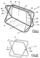
- a second self-supporting structure 100 embodying the invention which comprises first and second loops 110 and 120 intersecting with each other at two opposite positions A and B.
- the loops 110 and 120 are of similar shape and size and are formed by respective thin strips 130 of resilient and hence flexible material, such as metal.
- Each strip 130 is bent, without folding, to have opposite ends joint straight together, such that each loop 110/120 is self-expanding by virtue of its resilient nature. More specifically, each loop 110/120 is shaped to have a generally straight bottom portion 132 and a curved upper portion 134.
- positions A and B, at which the loops 110 and 120 intersect, are on the upper strip portions 134 and symmetrically on opposite sides of an imaginary vertical plane containing a central axis or axis of symmetry of and in the plane of each loop 110/120.
- the loops 110 and 120 are hinged together by means of respective pins 136A and 136B.
- the structure 100 also comprises connecting member for the loops 110 and 120.
- the connecting member is provided in the form of three flexible, fabric panels 140, 150 and 160 which connect the loops 110 and 120 together and extend across them, on their bottom, rear and top sides respectively, for stretching to limit the extent to which the loops 110 and 120 expand in space into a self-standing expanded configuration for use. While the structure 100 is standing on the ground, with the straight portions 132 of the strips 130 lowermost for stability, the first loop 110 leans backward and the second loop 120 is inclined forward. Each panel 140/150/160 closes the respective side of structure 100 between the parts of the loops 110 and 120 on that side from the hinges 136A and 136B. There is an additional flexible, fabric panel 170 which extends across the loop 110 alone and is formed with a central rectangular opening 172 on the front side of the structure 100. The opening 172 serves as an entrance for the structure 100 to be used as a play hut or tent.
- the panels 140, 150, 160 and 170 are sewed together along their adjoining peripheries in conjunction with a pair of separate loop-shaped fabric sleeves (not shown) which extend in the direction of the loops 110 and 120 along the panels' adjoining peripheries and the exposed front periphery of the top panel 160.
- the two sleeves are provided for holding the respective loops 110 and 120, thereby connecting the loops 110 and 120 and the panels 140, 150, 160 and 170 together.
- the loops 110 and 120 are held close together by means of peripheral parts of the panels.
- the panels 140, 150, 160 and 170 are sewed together with the two sleeves.
- the sleeves are left temporarily open at the two positions A and B, through which the two strips 130 are inserted into the sleeves and then joined end-to-end to form the respective loops 110 and 120.
- the loops 110 and 120 are subsequently hinged together by means of the pins 136A and 136B at positions A and B.
- the sleeves at positions A and B are sewed closed to complete the manufacture of the structure 100. It is appreciated that the pins 136A and 136B are optional since the top and bottom panels 160 and 140 connect and hold close together the loops 110 and 120.
- the loops 110 and 120 are pivotable to lie substantially flat with each other, with slight deformation as necessitated by the presence of the panels 140, 150, 160 and 170. subsequently, the loops 110 and 120 are capable of being simultaneously coiled into a plurality of much smaller turns, usually three turns for each loop 110/120, into a collapsed configuration for storage. Upon release, the structure 100 self-expands for use.
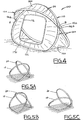
- Figures 5A to 5C show a pair of intersecting loops 10 and 20 similar to the aforesaid loops 110 and 120.
- the loops 10 and 20 may cross with each other at an intermediate position (Figure 5A) as in the case of the loops 110 and 120, or at an upper position (Figure 5B) or a lower position (Figure 5C). Further, the loops 10 and 20 may have different shapes and sizes (Figures 5D, 5E and 5F).
- FIG. 6A to 6I of the drawings there is shown a third self-supporting structure 200 embodying the invention, which has a construction in principle similar to that of the second structure 100.
- the third structure 200 is formed by a pair of oval resilient loops 210 and 220 intersecting symmetrically with each other at two opposite positions X and Y.
- the structure 200 includes top and bottom flexible panels 260 and 240 and a pair of opposite side flexible panels 270 and 250, extending across the loops 210 and 220.
- the top panel 260 has a wide central opening 262, which enables the structure 200, upon expansion and standing horizontally, to act as a basket for toys.
- the loops 210 and 220 are confined within sleeves co-extending with adjoining peripheries of the panels 240, 250, 260 and 270.
- the loops 210 and 220 are not directly hinged together at positions X and Y, but are held close together in a loose manner by reason of the parts of the sleeves there crossing with each other.
- Such an indirect connection is simpler in construction and allows the loops 210 and 220 to move more freely with respect to each other and to slide in their respective sleeves, thereby facilitating collapsing of the structure 200.
- the loops 210 and 220 are initially pivoted to lie flat with each other (Figure 6B), then squeezed to bring their opposite sides together (Figures 6C and 6D), and finally twisted and coiled into three much smaller turns ( Figures 6E, 6F, 6G, 6H and 6I) .
- the structure 200 springs open automatically for use.
- Figures 7 to 11 show fourth to eighth self-supporting structures 400, 500, 600, 700 and 800 embodying with the invention, which have a construction in principle similar to those of the first, second and third structures described above.
- the fourth structure 400 is similar to the second structure 100, except having an opening 402 which is defined by upper and lower straight portions of the two loops.
- the fifth structure 500 is also similar to the second structure 100, except having an opening 502 which is defined by an upturned round portion of one of the two loops.
- the sixth structure 600 is similar to the third structure 200, except having an asymmetrical shape.
- the two loops intersect with each other at a relatively higher position to form a pyramid-like tent having an open top end.
- an entrance 702 is formed at a near-rectangular side by making the panel there centrally openable.
- a similar entrance 802 is formed at a triangular side.
Landscapes
- Engineering & Computer Science (AREA)
- Architecture (AREA)
- Civil Engineering (AREA)
- Structural Engineering (AREA)
- Tents Or Canopies (AREA)
- Purses, Travelling Bags, Baskets, Or Suitcases (AREA)
Applications Claiming Priority (2)
| Application Number | Priority Date | Filing Date | Title |
|---|---|---|---|
| GB9914098 | 1999-06-17 | ||
| GB9914098A GB2351093A (en) | 1999-06-17 | 1999-06-17 | A portable self-erecting structure |
Publications (2)
| Publication Number | Publication Date |
|---|---|
| EP1061206A2 true EP1061206A2 (de) | 2000-12-20 |
| EP1061206A3 EP1061206A3 (de) | 2002-01-23 |
Family
ID=10855510
Family Applications (1)
| Application Number | Title | Priority Date | Filing Date |
|---|---|---|---|
| EP00305080A Withdrawn EP1061206A3 (de) | 1999-06-17 | 2000-06-15 | Selbsttragende und formstabile Struktur |
Country Status (3)
| Country | Link |
|---|---|
| EP (1) | EP1061206A3 (de) |
| AU (1) | AU4090900A (de) |
| GB (1) | GB2351093A (de) |
Cited By (4)
| Publication number | Priority date | Publication date | Assignee | Title |
|---|---|---|---|---|
| US7252107B2 (en) | 2003-03-27 | 2007-08-07 | Best Tide Mfg. Co., Ltd. | Pop up collapsible structures |
| ITUB20169874A1 (it) * | 2016-01-08 | 2017-07-08 | Pelleossa Srl | Involucro pieghevole utilizzabile come culla o tenda da campeggio. |
| CN107100422A (zh) * | 2017-05-17 | 2017-08-29 | 欧的珠 | 一种支撑架及使用该支撑架的蚊帐游戏蓬 |
| CN113982365A (zh) * | 2021-11-17 | 2022-01-28 | 南京国煜泰户外休闲用品有限公司 | 一种折叠帐篷 |
Families Citing this family (2)
| Publication number | Priority date | Publication date | Assignee | Title |
|---|---|---|---|---|
| DE20213664U1 (de) * | 2002-09-02 | 2002-11-07 | Tillmann, Marc, 10629 Berlin | Zusammenlegbares, wannenförmiges Behältnis |
| GB2460391A (en) * | 2008-02-28 | 2009-12-02 | Blacks Leisure Group Plc | Self erecting tent with integral canopy |
Citations (4)
| Publication number | Priority date | Publication date | Assignee | Title |
|---|---|---|---|---|
| US4815784A (en) | 1988-02-05 | 1989-03-28 | Yu Zheng | Automobile sunshield |
| US4825892A (en) | 1988-02-29 | 1989-05-02 | Pure Concepts, Inc. | Instantly stable, quickly erectable and quickly collapsible portable structure |
| US5038812A (en) | 1989-08-18 | 1991-08-13 | Spring Form, Inc. | Quickly erectable, quickly collapsible, self supporting portable structure |
| US5427381A (en) | 1994-09-29 | 1995-06-27 | Macaluso; Anthony G. | Sports net |
Family Cites Families (4)
| Publication number | Priority date | Publication date | Assignee | Title |
|---|---|---|---|---|
| US5137044A (en) * | 1990-10-12 | 1992-08-11 | Brady David S | Collapsible tent structure |
| EP0545637A1 (de) * | 1991-11-29 | 1993-06-09 | Gartin, Jack H. | Selbst-entfaltbare, tragbare Struktur und Methode |
| US5337772A (en) * | 1993-04-12 | 1994-08-16 | Habchi Elie E | Self-unfolding shelter |
| US5439017A (en) * | 1994-06-07 | 1995-08-08 | Blue Leaf Design, Inc. | Collapsible frame |
-
1999
- 1999-06-17 GB GB9914098A patent/GB2351093A/en not_active Withdrawn
-
2000
- 2000-06-15 EP EP00305080A patent/EP1061206A3/de not_active Withdrawn
- 2000-06-16 AU AU40909/00A patent/AU4090900A/en not_active Abandoned
Patent Citations (4)
| Publication number | Priority date | Publication date | Assignee | Title |
|---|---|---|---|---|
| US4815784A (en) | 1988-02-05 | 1989-03-28 | Yu Zheng | Automobile sunshield |
| US4825892A (en) | 1988-02-29 | 1989-05-02 | Pure Concepts, Inc. | Instantly stable, quickly erectable and quickly collapsible portable structure |
| US5038812A (en) | 1989-08-18 | 1991-08-13 | Spring Form, Inc. | Quickly erectable, quickly collapsible, self supporting portable structure |
| US5427381A (en) | 1994-09-29 | 1995-06-27 | Macaluso; Anthony G. | Sports net |
Cited By (5)
| Publication number | Priority date | Publication date | Assignee | Title |
|---|---|---|---|---|
| US7252107B2 (en) | 2003-03-27 | 2007-08-07 | Best Tide Mfg. Co., Ltd. | Pop up collapsible structures |
| ITUB20169874A1 (it) * | 2016-01-08 | 2017-07-08 | Pelleossa Srl | Involucro pieghevole utilizzabile come culla o tenda da campeggio. |
| CN107100422A (zh) * | 2017-05-17 | 2017-08-29 | 欧的珠 | 一种支撑架及使用该支撑架的蚊帐游戏蓬 |
| CN113982365A (zh) * | 2021-11-17 | 2022-01-28 | 南京国煜泰户外休闲用品有限公司 | 一种折叠帐篷 |
| CN113982365B (zh) * | 2021-11-17 | 2023-03-10 | 南京国煜泰户外休闲用品有限公司 | 一种折叠帐篷 |
Also Published As
| Publication number | Publication date |
|---|---|
| GB9914098D0 (en) | 1999-08-18 |
| EP1061206A3 (de) | 2002-01-23 |
| AU4090900A (en) | 2000-12-21 |
| GB2351093A (en) | 2000-12-20 |
Similar Documents
| Publication | Publication Date | Title |
|---|---|---|
| US6267128B1 (en) | Collapsible structures | |
| US7225822B1 (en) | Collapsible structures | |
| US7048654B2 (en) | Collapsible structures | |
| US6694994B1 (en) | Collapsible structures | |
| US6460556B2 (en) | Adjustable collapsible panels | |
| US6491052B1 (en) | Collapsible panels having multiple frame members | |
| US6668847B2 (en) | Collapsible structures | |
| US6267129B1 (en) | Collapsible frame assemblies | |
| JP2001140503A (ja) | コイル状に折り曲げ自在な支持部材を備えている折り畳み式布構造体及び該構造体を折り畳む方法 | |
| US8667626B2 (en) | Collapsible baby play station | |
| US6698441B1 (en) | Collapsible structures | |
| US20170114566A1 (en) | System of collapsible panels and structures | |
| US20100155397A1 (en) | Collapsible structures with liners | |
| JP2001050483A (ja) | 多角形リンクを有する可逆的に伸張可能な構造体 | |
| EP1559854A2 (de) | Zusammenlegbare Stoffstruktur | |
| US20070039640A1 (en) | Collapsible structures | |
| US6244011B1 (en) | Inverted V-shaped display framework | |
| GB2351093A (en) | A portable self-erecting structure | |
| US7987865B2 (en) | Collapsible panel assembly | |
| US20250205571A1 (en) | Portable multifunctional soccer goal | |
| GB2451651A (en) | Pop up structure | |
| KR200150040Y1 (ko) | 빠르게 펴고 접을 수 있는 레져용 휴대용 구조물 | |
| GB2355472A (en) | Collapsible fabric structures with coilable supports | |
| GB2221836A (en) | Collapsible support frame |
Legal Events
| Date | Code | Title | Description |
|---|---|---|---|
| PUAI | Public reference made under article 153(3) epc to a published international application that has entered the european phase |
Free format text: ORIGINAL CODE: 0009012 |
|
| AK | Designated contracting states |
Kind code of ref document: A2 Designated state(s): AT BE CH CY DE DK ES FI FR GB GR IE IT LI LU MC NL PT SE |
|
| AX | Request for extension of the european patent |
Free format text: AL;LT;LV;MK;RO;SI |
|
| RIN1 | Information on inventor provided before grant (corrected) |
Inventor name: YU, KING WAY SIDNEY Inventor name: YU, TERESA Inventor name: SU, SHI WEI |
|
| PUAL | Search report despatched |
Free format text: ORIGINAL CODE: 0009013 |
|
| AK | Designated contracting states |
Kind code of ref document: A3 Designated state(s): AT BE CH CY DE DK ES FI FR GB GR IE IT LI LU MC NL PT SE |
|
| AX | Request for extension of the european patent |
Free format text: AL;LT;LV;MK;RO;SI |
|
| AKX | Designation fees paid | ||
| REG | Reference to a national code |
Ref country code: DE Ref legal event code: 8566 |
|
| STAA | Information on the status of an ep patent application or granted ep patent |
Free format text: STATUS: THE APPLICATION IS DEEMED TO BE WITHDRAWN |
|
| 18D | Application deemed to be withdrawn |
Effective date: 20020724 |