EP1061115A1 - Improved fischer-tropsch process - Google Patents
Improved fischer-tropsch process Download PDFInfo
- Publication number
- EP1061115A1 EP1061115A1 EP00202032A EP00202032A EP1061115A1 EP 1061115 A1 EP1061115 A1 EP 1061115A1 EP 00202032 A EP00202032 A EP 00202032A EP 00202032 A EP00202032 A EP 00202032A EP 1061115 A1 EP1061115 A1 EP 1061115A1
- Authority
- EP
- European Patent Office
- Prior art keywords
- solid
- liquid
- particle
- particles
- column
- Prior art date
- Legal status (The legal status is an assumption and is not a legal conclusion. Google has not performed a legal analysis and makes no representation as to the accuracy of the status listed.)
- Granted
Links
- 238000000034 method Methods 0.000 title claims abstract description 38
- 239000007787 solid Substances 0.000 claims abstract description 119
- 239000002245 particle Substances 0.000 claims abstract description 111
- 239000007789 gas Substances 0.000 claims abstract description 39
- 238000006243 chemical reaction Methods 0.000 claims abstract description 37
- 238000000926 separation method Methods 0.000 claims abstract description 29
- 229930195733 hydrocarbon Natural products 0.000 claims abstract description 13
- 150000002430 hydrocarbons Chemical class 0.000 claims abstract description 13
- 239000003153 chemical reaction reagent Substances 0.000 claims abstract description 10
- 230000003197 catalytic effect Effects 0.000 claims abstract description 8
- 238000004519 manufacturing process Methods 0.000 claims abstract description 4
- 239000007788 liquid Substances 0.000 claims description 53
- 239000003054 catalyst Substances 0.000 claims description 39
- 239000006185 dispersion Substances 0.000 claims description 23
- 229910017052 cobalt Inorganic materials 0.000 claims description 13
- 239000010941 cobalt Substances 0.000 claims description 13
- GUTLYIVDDKVIGB-UHFFFAOYSA-N cobalt atom Chemical compound [Co] GUTLYIVDDKVIGB-UHFFFAOYSA-N 0.000 claims description 13
- 239000007791 liquid phase Substances 0.000 claims description 11
- 239000000203 mixture Substances 0.000 claims description 7
- 229910002091 carbon monoxide Inorganic materials 0.000 claims description 3
- PNEYBMLMFCGWSK-UHFFFAOYSA-N aluminium oxide Inorganic materials [O-2].[O-2].[O-2].[Al+3].[Al+3] PNEYBMLMFCGWSK-UHFFFAOYSA-N 0.000 claims description 2
- 230000001131 transforming effect Effects 0.000 claims description 2
- 238000013386 optimize process Methods 0.000 abstract 1
- 239000002002 slurry Substances 0.000 description 19
- 239000012071 phase Substances 0.000 description 15
- 239000001993 wax Substances 0.000 description 14
- 230000007423 decrease Effects 0.000 description 13
- 230000000694 effects Effects 0.000 description 13
- 238000002156 mixing Methods 0.000 description 10
- 238000009826 distribution Methods 0.000 description 9
- 238000005470 impregnation Methods 0.000 description 8
- 239000007790 solid phase Substances 0.000 description 8
- 239000012263 liquid product Substances 0.000 description 6
- 229910052751 metal Inorganic materials 0.000 description 6
- 239000002184 metal Substances 0.000 description 6
- 235000020030 perry Nutrition 0.000 description 6
- 230000001133 acceleration Effects 0.000 description 5
- 239000000725 suspension Substances 0.000 description 5
- IJGRMHOSHXDMSA-UHFFFAOYSA-N Atomic nitrogen Chemical compound N#N IJGRMHOSHXDMSA-UHFFFAOYSA-N 0.000 description 4
- GWEVSGVZZGPLCZ-UHFFFAOYSA-N Titan oxide Chemical compound O=[Ti]=O GWEVSGVZZGPLCZ-UHFFFAOYSA-N 0.000 description 4
- 230000015572 biosynthetic process Effects 0.000 description 4
- 238000009835 boiling Methods 0.000 description 4
- 238000001914 filtration Methods 0.000 description 4
- 238000005243 fluidization Methods 0.000 description 4
- 230000003068 static effect Effects 0.000 description 4
- 239000000126 substance Substances 0.000 description 4
- 238000003786 synthesis reaction Methods 0.000 description 4
- 241000209094 Oryza Species 0.000 description 3
- 235000007164 Oryza sativa Nutrition 0.000 description 3
- 150000004945 aromatic hydrocarbons Chemical class 0.000 description 3
- 238000005119 centrifugation Methods 0.000 description 3
- 150000001875 compounds Chemical class 0.000 description 3
- 239000001257 hydrogen Substances 0.000 description 3
- 229910052739 hydrogen Inorganic materials 0.000 description 3
- 150000002739 metals Chemical class 0.000 description 3
- 230000009467 reduction Effects 0.000 description 3
- 235000009566 rice Nutrition 0.000 description 3
- XKRFYHLGVUSROY-UHFFFAOYSA-N Argon Chemical compound [Ar] XKRFYHLGVUSROY-UHFFFAOYSA-N 0.000 description 2
- UGFAIRIUMAVXCW-UHFFFAOYSA-N Carbon monoxide Chemical compound [O+]#[C-] UGFAIRIUMAVXCW-UHFFFAOYSA-N 0.000 description 2
- UFHFLCQGNIYNRP-UHFFFAOYSA-N Hydrogen Chemical compound [H][H] UFHFLCQGNIYNRP-UHFFFAOYSA-N 0.000 description 2
- XEEYBQQBJWHFJM-UHFFFAOYSA-N Iron Chemical compound [Fe] XEEYBQQBJWHFJM-UHFFFAOYSA-N 0.000 description 2
- 150000001336 alkenes Chemical class 0.000 description 2
- 238000013459 approach Methods 0.000 description 2
- QVGXLLKOCUKJST-UHFFFAOYSA-N atomic oxygen Chemical compound [O] QVGXLLKOCUKJST-UHFFFAOYSA-N 0.000 description 2
- 229910052799 carbon Inorganic materials 0.000 description 2
- 239000000969 carrier Substances 0.000 description 2
- 230000003247 decreasing effect Effects 0.000 description 2
- 238000005516 engineering process Methods 0.000 description 2
- 238000000605 extraction Methods 0.000 description 2
- 239000012530 fluid Substances 0.000 description 2
- 230000005484 gravity Effects 0.000 description 2
- 238000010438 heat treatment Methods 0.000 description 2
- DCAYPVUWAIABOU-UHFFFAOYSA-N hexadecane Chemical compound CCCCCCCCCCCCCCCC DCAYPVUWAIABOU-UHFFFAOYSA-N 0.000 description 2
- 229910052809 inorganic oxide Inorganic materials 0.000 description 2
- 229910044991 metal oxide Inorganic materials 0.000 description 2
- 150000004706 metal oxides Chemical class 0.000 description 2
- VNWKTOKETHGBQD-UHFFFAOYSA-N methane Chemical compound C VNWKTOKETHGBQD-UHFFFAOYSA-N 0.000 description 2
- 229910052757 nitrogen Inorganic materials 0.000 description 2
- ZYURHZPYMFLWSH-UHFFFAOYSA-N octacosane Chemical group CCCCCCCCCCCCCCCCCCCCCCCCCCCC ZYURHZPYMFLWSH-UHFFFAOYSA-N 0.000 description 2
- 239000001301 oxygen Substances 0.000 description 2
- 229910052760 oxygen Inorganic materials 0.000 description 2
- 238000012856 packing Methods 0.000 description 2
- 230000008929 regeneration Effects 0.000 description 2
- 238000011069 regeneration method Methods 0.000 description 2
- 238000004062 sedimentation Methods 0.000 description 2
- 239000002904 solvent Substances 0.000 description 2
- POILWHVDKZOXJZ-ARJAWSKDSA-M (z)-4-oxopent-2-en-2-olate Chemical compound C\C([O-])=C\C(C)=O POILWHVDKZOXJZ-ARJAWSKDSA-M 0.000 description 1
- QTBSBXVTEAMEQO-UHFFFAOYSA-M Acetate Chemical compound CC([O-])=O QTBSBXVTEAMEQO-UHFFFAOYSA-M 0.000 description 1
- 239000004215 Carbon black (E152) Substances 0.000 description 1
- 229910002651 NO3 Inorganic materials 0.000 description 1
- NHNBFGGVMKEFGY-UHFFFAOYSA-N Nitrate Chemical compound [O-][N+]([O-])=O NHNBFGGVMKEFGY-UHFFFAOYSA-N 0.000 description 1
- KJTLSVCANCCWHF-UHFFFAOYSA-N Ruthenium Chemical compound [Ru] KJTLSVCANCCWHF-UHFFFAOYSA-N 0.000 description 1
- 229910052776 Thorium Inorganic materials 0.000 description 1
- 229910052782 aluminium Inorganic materials 0.000 description 1
- 150000001412 amines Chemical class 0.000 description 1
- 229910052786 argon Inorganic materials 0.000 description 1
- 238000001354 calcination Methods 0.000 description 1
- 125000004432 carbon atom Chemical group C* 0.000 description 1
- 239000012876 carrier material Substances 0.000 description 1
- 238000009903 catalytic hydrogenation reaction Methods 0.000 description 1
- 239000012295 chemical reaction liquid Substances 0.000 description 1
- 239000007795 chemical reaction product Substances 0.000 description 1
- 238000000975 co-precipitation Methods 0.000 description 1
- 238000011960 computer-aided design Methods 0.000 description 1
- 238000010276 construction Methods 0.000 description 1
- 238000013461 design Methods 0.000 description 1
- 238000009792 diffusion process Methods 0.000 description 1
- 150000002170 ethers Chemical class 0.000 description 1
- 230000002349 favourable effect Effects 0.000 description 1
- 238000001879 gelation Methods 0.000 description 1
- 238000001033 granulometry Methods 0.000 description 1
- 239000001307 helium Substances 0.000 description 1
- 229910052734 helium Inorganic materials 0.000 description 1
- SWQJXJOGLNCZEY-UHFFFAOYSA-N helium atom Chemical compound [He] SWQJXJOGLNCZEY-UHFFFAOYSA-N 0.000 description 1
- 150000002431 hydrogen Chemical class 0.000 description 1
- 239000011261 inert gas Substances 0.000 description 1
- 229910052742 iron Inorganic materials 0.000 description 1
- 229910052749 magnesium Inorganic materials 0.000 description 1
- 238000012423 maintenance Methods 0.000 description 1
- 239000000463 material Substances 0.000 description 1
- 150000002736 metal compounds Chemical class 0.000 description 1
- 229920013639 polyalphaolefin Polymers 0.000 description 1
- 238000001556 precipitation Methods 0.000 description 1
- 239000000047 product Substances 0.000 description 1
- 239000010453 quartz Substances 0.000 description 1
- 230000001105 regulatory effect Effects 0.000 description 1
- 230000006833 reintegration Effects 0.000 description 1
- 230000000630 rising effect Effects 0.000 description 1
- 229910052707 ruthenium Inorganic materials 0.000 description 1
- 229930195734 saturated hydrocarbon Natural products 0.000 description 1
- 238000007873 sieving Methods 0.000 description 1
- 229910052710 silicon Inorganic materials 0.000 description 1
- VYPSYNLAJGMNEJ-UHFFFAOYSA-N silicon dioxide Inorganic materials O=[Si]=O VYPSYNLAJGMNEJ-UHFFFAOYSA-N 0.000 description 1
- 239000011949 solid catalyst Substances 0.000 description 1
- 241000894007 species Species 0.000 description 1
- 238000009210 therapy by ultrasound Methods 0.000 description 1
- 229910052718 tin Inorganic materials 0.000 description 1
- 229910052719 titanium Inorganic materials 0.000 description 1
- 238000011144 upstream manufacturing Methods 0.000 description 1
- 229910052725 zinc Inorganic materials 0.000 description 1
Images



Classifications
-
- C—CHEMISTRY; METALLURGY
- C10—PETROLEUM, GAS OR COKE INDUSTRIES; TECHNICAL GASES CONTAINING CARBON MONOXIDE; FUELS; LUBRICANTS; PEAT
- C10G—CRACKING HYDROCARBON OILS; PRODUCTION OF LIQUID HYDROCARBON MIXTURES, e.g. BY DESTRUCTIVE HYDROGENATION, OLIGOMERISATION, POLYMERISATION; RECOVERY OF HYDROCARBON OILS FROM OIL-SHALE, OIL-SAND, OR GASES; REFINING MIXTURES MAINLY CONSISTING OF HYDROCARBONS; REFORMING OF NAPHTHA; MINERAL WAXES
- C10G2/00—Production of liquid hydrocarbon mixtures of undefined composition from oxides of carbon
- C10G2/30—Production of liquid hydrocarbon mixtures of undefined composition from oxides of carbon from carbon monoxide with hydrogen
- C10G2/32—Production of liquid hydrocarbon mixtures of undefined composition from oxides of carbon from carbon monoxide with hydrogen with the use of catalysts
- C10G2/34—Apparatus, reactors
- C10G2/342—Apparatus, reactors with moving solid catalysts
Definitions
- the present invention relates to an improved process for the Fischer-Tropsch reaction, which essentially consists in a first reaction phase in a gas-liquid-solid fluidized reactor and a second separation phase, at least partial, internal or external, of the solid suspension in the liquid.
- the Fischer-Tropsch reaction consists in the production of essentially linear and saturated hydrocarbons, preferably having at least 5 carbon atoms in the molecule, by means of the catalytic hydrogenation of CO, optionally diluted with CO 2 .
- the reaction between CO and H 2 is carried out in a gas-liquid-solid fluidized reactor in which the solid, prevalently consisting of particles of catalyst, is suspended by means of the gas stream and liquid stream.
- the former prevalently consists of reagent species, i.e. CO and H 2
- the latter consists of hydrocarbons produced by the Fischer-Tropsch reaction, optionally at least partially recycled, either from the material liquid under the process conditions, or the relative mixtures.
- the gas and liquid, optionally recycled, are fed from the bottom of the column by means of appropriate distributors and the flow-rates of the gas and liquid are such as to guarantee a turbulent flow regime in the column.
- the flow-rates of the fluids should be such as to guarantee a practically homogeneous suspension of the solid in the whole reaction volume and facilitate the removal of the heat produced by the exothermic reaction, improving the heat exchange between the reaction zone and a suitable exchanger device inserted in the column.
- the solid particles should have dimensions which are sufficiently large as to enable them to be easily separated from the liquid products, but sufficiently small as to render the diffusive intra-particle limitations negligible (unitary particle efficiency) and enable them to be easily fluidized.
- the average diameter of the solid particles used in slurry reactors can vary from 1 to 200 ⁇ m, although operating with dimensions of less than 10 ⁇ m makes the separation of the solid from the liquid products extremely expensive.
- d p is the average particle diameter
- ⁇ s is the density of the solid
- ⁇ l is the density of the liquid
- ⁇ the viscosity of the liquid
- g the gravity acceleration
- f(C p ) represents the hindering function due to the presence of other particles and depending on the volumetric concentration of the particles C p .
- EP'860 is very incomplete and discloses, moreover, the use of particles with very small dimensions, with obvious limits in the solid - liquid separation step.
- the technical problem of EP'860 relates only to the reaction phase and not to the whole process, comprising both the reaction and solid-liquid separation.
- EP'860 does not indicate any method or correlation for determining the axial dispersion coefficient of the solid, D (a fundamental parameter in verifying the constraint (1)), neither does it provide any experimental values of D for comparison.
- D a fundamental parameter in verifying the constraint (1)
- the concentration of the solid proves to decrease from the bottom to the top of the reaction volume by a factor of 7.4. If this height is halved, the reduction factor of the concentration of the solid decreases to 2.4 which however is very high.
- an optimum condition for a slurry reactor should comprise a uniform concentration profile in the whole catalyst volume.
- EP-A-450,860 also discloses operating according to Stokes' law: it is in fact known in literature that the term 1 18 . d 2 p ⁇ s - ⁇ l ⁇ L . g , introduced in the definition of U s of equation (2), represents the terminal settling velocity of the particle, U t , according to Stokes' law. This law (see Perry's Chemical Engineers' Handbook, 6 th Ed.) is valid in the laminar regime when the Reynolds' particle number Re p is less than 0.1.
- EP'860 discloses operating with particle dimensions of over 5 ⁇ m, but not exceeding the limit value of d p established by Stokes' law.
- the present invention relates to an optimized method for the production of heavy hydrocarbons according to the Fischer-Tropsch process and the relative separation of the above hydrocarbons, starting from mixtures of reagent gases, essentially consisting of CO and H 2 , optionally diluted with CO 2 , in the presence of supported catalysts, which comprises:
- the catalysts used in the process of the present invention generally comprise metals of Group VIII, such as Iron, Cobalt, Ruthenium or relative mixtures on carriers of inorganic oxides.
- the above catalysts may contain additional promoters comprising metals selected from those of Group I, Group II, Group V, Group VII, alone or in mixtures.
- the preferred catalysts which can be used in the process of the present invention comprise cobalt, optionally containing promoters, supported on inorganic oxides of at least one of the elements selected from Si, Ti, Al, Zn, Sn, Mg, Th.
- the surface area of the carrier is concerned, this is within the range of 20-300 m 2 /g, preferably 50-200 m 2 /g (BET).
- promoters When promoters are contained, these are present in such a quantity as to have a weight ratio between promoter and cobalt of 0.01/1 to 1/1, preferably from 0.025/1 to 0.1/1.
- the catalyst When the catalyst contains cobalt, it is present in a quantity ranging from 2 to 50% by weight, preferably from 5 to 20% by weight.
- the catalysts which can be used in the process of the present invention can be prepared with the known techniques, for examples by means of gelation, cogelation, impregnation, precipitation, dry impregnation, co-precipitation or mechanical mixing.
- the cobalt and optional promoters are linked to the carrier by putting the carrier itself in contact with a solution of a compound containing cobalt (or other possible promoters) by means of impregnation.
- the cobalt and possible promoters can be co-impregnated on the carrier itself.
- the compounds of Cobalt and optional promoters used in the impregnation can consist of any organic or inorganic metal compound susceptible to decomposing after heating in nitrogen, argon, helium or another inert gas, calcination in a gas containing oxygen, or treatment with hydrogen, at high temperatures, to give the corresponding metal, metal oxide, or mixtures of the metal or metal oxide phases.
- Cobalt and possible promoters
- Compounds of Cobalt can be used, such as nitrate, acetate, acetylacetonate, carbonyl naphthenate and the like.
- the quantity of impregnation solution should be sufficient to completely wet the carrier, usually within a range of about 1 to 20 times the carrier by volume, depending on the concentration of metal (or metals) in the impregnation solution.
- the impregnation treatment can be carried out within a wide range of temperature conditions.
- the catalyst is dried by heating to a temperature of over 30°C, preferably from 30°C to 125°C, in the presence of nitrogen or oxygen, or both or air, in a gas stream or under partial vacuum.
- the catalyst particle distribution is obtained within the desired dimensional range by the use of preformed carriers or with the usual techniques such as crushing, ultrasonic treatment or other procedures.
- the catalyst particles are treated to obtain the desired dimensions using known techniques such as, for example, sieving.
- the liquid phase necessary for fluidizing the catalyst can be any substance liquid under the reaction pressure and temperature conditions, capable of maintaining the catalyst under suspension, relatively inert under the reaction conditions, and of being a good solvent for carbon monoxide and hydrogen.
- Typical examples of organic liquids which can be used in the present process are paraffins, olefins, aromatic hydrocarbons, ethers, amines and relative mixtures, provided they are high-boiling.
- High-boiling paraffins comprise C 10 -C 50 linear or branched paraffins;
- high-boiling olefins comprise liquid polyalpha-olefins;
- high-boiling aromatic hydrocarbons comprise single, multiple or condensed ring aromatic hydrocarbons.
- the preferred liquid hydrocarbon solvent is octacosane or hexadecane; n-paraffinic wax, i.e. the Fischer-Tropsch reaction product, is even more preferable.
- the reaction conditions for the Fischer-Tropsch process are generally known to experts in the field.
- the temperature normally ranges from 160°C to 360°C, preferably from 190°C to 230°C, even more preferably from 190 to 220°C.
- the pressures are usually higher than 6 bars, preferably from 6 to 60 bars, more preferably from 10 to 30 bars.
- the ratios between carbon monoxide and hydrogen can vary within a wide range.
- the stoichiometric ratio H 2 /CO in the Fischer-Tropsch process is 2.1/1, in most cases a lower H 2 /CO ratio is used.
- H 2 /CO ratios ranging from 1/2 to 1/1.4.
- the process of the present invention is not limited to low H 2 /CO ratios.
- H 2 /CO ratios ranging from about 1.5/1 to about 2.5/1, preferably from about 1.2/1 to about 2.2/1, can be used.
- the catalyst is suspended and mixed prevalently by the movement induced by the bubbles of gas which rise along the column.
- the present invention refers to a gas-liquid-solid system in which the gas flow-rate is such as to have a turbulent flow regime, characterized by a wide distribution of the bubble diameters (3-80 mm approx.) which rise through the column.
- the mixing and distribution of the catalyst inside the bubble column reactor prevalently derives from the fraction of gas which runs through the column in the form of large bubbles (about 20-80 mm), and drags in its upward motion, at a rising rate of the large bubbles in the order of 1-2 m/s approximately, both the liquid and solid suspended in the liquid.
- the gas therefore causes macro-vortexes of the continuous phase (liquid) in which the solid is suspended, increasing the dispersion degree of the solid and consequently the uniformity of the axial concentration profile of the solid, with respect to operating in a homogeneous flow regime (low gas flow-rates, gas bubbles uniformly distributed and with small dimensions, 3-6 mm).
- the process of the present invention comprises operating, in the reaction step (a), with a Reynolds ' number of the catalytic particle Re p > 0.1, preferably from 0.11 to 50.
- the Reynolds' number is a function of the density and viscosity of the liquid phase and also of the density of the catalyst particle and its dimensions.
- the Reynolds' number may only vary in relation to the density and dimensions of the catalytic particles.
- the expert in the field who knows the density of the catalytic particles he intends to use (normally similar to the density of the inert carrier material), can obtain the average diameter of particles which are such as to have a Reynolds' number greater than 0.1, preferably from 0.11 to 50, even more preferably from 0.2 to 25.
- Step (b) of the process of the present invention comprises recovering, at least partially, the liquid products generated by the Fischer-Tropsch reaction by means of extraction from the reaction zone of a certain amount of slurry (liquid + solid).
- the separation of the desired quantity of liquid products is effected using equipment such as for example hydrocyclones or filters (tangential or frontal) or, preferably, static decanters.
- the separation step also generates a more concentrated slurry which can be recycled directly to the Fischer-Tropsch reactor, or it can be treated in a regeneration step of the catalyst or it can be partially removed to introduce fresh catalyst.
- the whole extraction process of the slurry for the separation of the liquid products and reintegration of the more concentrated slurry, partially regenerated and/or substituted, is regulated so as to keep the reaction volume and average concentration of the catalyst constant.
- step (b) of the process of the present invention is carried out under favourable conditions. It is known, in fact, that for a certain flow-rate of slurry (liquid + solid), with an increase in the particle diameter, not only are the volumes of the separation section reduced, but the type of equipment necessary for separating the liquid products from the concentrated slurry is simplified. When particles having an average diameter of 150 ⁇ m rather than 5 ⁇ m are adopted, and with the use of hydrocyclones as separation devices, the unit number is drastically reduced; at the same time the dimensions of the single unit can be increased, thus facilitating the construction of the hydrocyclones themselves (see example 8 for further details). For particles having an average diameter higher than 100-150 ⁇ m it is possible to substitute the hydrocyclones with static separators (decanters), making the separation step easier and less expensive.
- the process of the present invention is characterized in that it is effected not only within a certain Reynolds' number range, but also under such conditions as to have a reasonably uniform concentration profile of the solid, C p (x), along the reaction column; for example a profile C p (x) which varies by a maximum value of ⁇ 20% with respect to the average concentration value of the solid (catalyst), C p .
- This is equivalent to having a Bodenstein number (Bo s ) less than or equal to 0.4.
- the concentration profile of the solid with respect to the axial co-ordinate of the bubble column reactor is thus expressed as a function of the Bodenstein number, Bo s , which among other parameters, is a function of the diameter of the column.
- Bo s which among other parameters, is a function of the diameter of the column.
- the minimum diameter of the column sufficient to respect the constraint set for obtaining an optimum distribution of the solid.
- the value of this diameter is also a function of the solid particle dimensions. With an increase in the average diameter of the particles, the minimum diameter of the column increases: it is therefore possible to obtain an excellent dispersion of the solid phase by suitably dimensioning the reactor.
- figure 1 represents the trend of the average diameter of the particles of solid catalyst in relation to the density of the above solid for a given liquid phase, discriminating the validity zone of Stokes' law (Re p ⁇ 0.1).
- Figure 2 represents the trend of U t (terminal settling velocity of the solid) and Re p as a function of d p (average diameter of the solid) for the liquid-solid system of example 3, discriminating the validity zone of Stokes' law.
- Figure 3 represents the normalized axial concentration profile of the solid (C p (x)/ C p ) for various values of the Bo s parameter, precisely 0.4, 1 and 2.
- Figure 4 indicates the trend of the column diameter as a function of the average particle diameter with variations in the average concentration of solid in the column to satisfy the requirement of example 7.
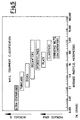
- Figure 5 shows a classification of the solid-liquid separation equipment, of the wall solid type, as a function of the particle size.
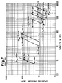
- Figure 6 shows a classification of the solid-liquid separation equipment, of the filtration type, as a function of the particle size.
- Figure 7 indicates the utilization fields of commercial hydrocyclones having various dimensions in relation to the GPM (gallons per minute) capacity, of the operating pressure loss and particle dimension.
- the patent EP'860 describes a method for optimizing the operating conditions of a slurry bubble column, in which the dimensions of the solid particles to be introduced into the column must be greater than 5 ⁇ m.
- U s 1 18 . d p 2 ⁇ s - ⁇ l ⁇ . g . f(C p )
- the above formula for U s mainly consists of two terms:
- EP'860 discloses operating with a system wherein Stokes' law is valid.
- Example 8 of EP'860 gives the properties of the solid and liquid useful for determining U s , which are:
- the limit value of d p changes, i.e. with an increase in the density of the particle, the average particle dimension at which Re p is less than 0.1, decreases.
- Figure 1 shows the effect of the particle density on the limit value of d p so that Stokes' law is valid, when the properties of the liquid are the same as those described in example 1, whereas ⁇ s varies from 1 to 3 g/cm 3 .
- the particles must have average dimensions d p ⁇ 38 ⁇ m.
- Figure 2 indicates the value of U t as a function of d p (within the range 5 ⁇ m ⁇ d p ⁇ 1000 ⁇ m) when the following are valid for the system:
- Figure 2 also shows the corresponding value of Re p ; as can be observed, for particles with an average diameter higher than 38 ⁇ m, the Reynolds' number Re p is greater than 0.1 and U t is determined by means of the Eq. (E.5).
- f(C p ) (1-C p ) n and is practically equal to 1 for very dilute slurry (liquid-solid) systems (C p -> 0), whereas it monotonically decreases with an increase in C p , until it tends towards values close to 0 for very concentrated slurry systems (maximum packing).
- n 4.1721.Re p -0.0658
- the dispersion coefficient of the solid, D ax,s , along the axial co-ordinate of the three-phase column reactor is a parameter which is difficult to determine.
- Figure 3 shows the normalized concentration profile (C p (x)/ C p ) for various values of the Bo s parameter.
- Figure 4 indicates the example relating to the following system:
- the curves, parametric in the average volumetric concentration of the solid, C p ( or C p,average ), indicate the minimum column diameter to satisfy the constraint (E.11) as a function of the average particle diameter.
- the volumetric concentration of the solid varies from 5 to 30% v/v.
- Curves analogous to those of figure 4 can be drawn for different particle densities, varying H and U g .
- the selection of U g 0.08 m/s made in this example, refers to a minimum gas rate for having a completely developed churn-turbulent flow regime. By increasing the gas rate, the dispersion of the solid increases, and therefore the minimum diameter for verifying the constraint (E.11) is reduced; the same thing occurs when the dispersion height is reduced.
- the relative Bo s value is equal to 0.26 ⁇ 0.4
- the constraint (E.11) is thus respected and the concentration profile of the solid, expressed by the Eq. (E.9) proves to be within the range of ⁇ 13% of the average concentration of the solid, C p , which in this example is equal to 20% v/v.
- Figure 5 shows a classification of solid-liquid separation equipment, of the solid wall type, as a function of the particle size.
- the equipment is classified according to two different functioning principles: for dynamic decanting (in which the acceleration induced on the particles is important) and for static decanting (in which the surface characteristic of the decanter is important) From figure 5 it can be observed that, with an increase in the particle dimension, the gravitational acceleration required (G number) or surface desired, respectively decrease. Reducing the G number means decreasing the rotation rate, and therefore saving energy. Reducing the surface means reducing the size of the equipment.
- Figure 6 shows a classification of solid-liquid separation equipment, of the filtration type, as a function of the particle size.
- the equipment is classified according to two different functioning principles: for filtration under pressure (in which the difference in pressure exerted between upstream and downstream of the filter, is important) and for filtrating centrifugation (in which the acceleration induced on the particles is important).
- G number gravitational acceleration required
- Figure 7 shows the utilization fields of commercial hydrocyclones of various sizes as a function of the GPM capacity, operating pressure loss and particle size.
- a hydrocyclone is a static apparatus which exploits the difference in density between solid and liquid and the centrifugal power induced, for separating the solid particles from the fluid in which they are suspended. For example, assuming a capacity of 680 m 3 /h of liquid-solid suspension to be treated, equal to about 3000 GPM (specific gravity of the solid 2.7, concentration of the solid of 25% by weight, and separation efficiency of 95%), it can be observed that increasing the granulometry of the solid particles, it is possible to use a smaller number of hydrocyclones, but with a larger diameter, according to the following table: Particle Diameter Diameter hydrocyc. Total capacity/Single hydrocycl. Capacity Number hydrocycl.
- the examples also describe a possible approach for estimating "a priori" the axial dispersion coefficient of the solid, D ax,s , for a gas-liquid-solid fluidized reactor of a commercial size (diameter > 1 m).
Landscapes
- Chemical & Material Sciences (AREA)
- Oil, Petroleum & Natural Gas (AREA)
- Engineering & Computer Science (AREA)
- Chemical Kinetics & Catalysis (AREA)
- General Chemical & Material Sciences (AREA)
- Organic Chemistry (AREA)
- Devices And Processes Conducted In The Presence Of Fluids And Solid Particles (AREA)
- Organic Low-Molecular-Weight Compounds And Preparation Thereof (AREA)
- Transition And Organic Metals Composition Catalysts For Addition Polymerization (AREA)
- Catalysts (AREA)
- Production Of Liquid Hydrocarbon Mixture For Refining Petroleum (AREA)
- Epoxy Resins (AREA)
- Organic Insulating Materials (AREA)
- Solid-Sorbent Or Filter-Aiding Compositions (AREA)
Abstract
Description
the above process being characterized in that in step (a) the reaction takes place:
-
- f(Cp) which represents the hindering effect due to the presence of other particles, i.e. to the concentration of the solid, and which is practically equal to 1 for extremely dilute slurry systems (liquid-solid), and tends towards 0 for very concentrated slurry systems (maximum packing).
- density of the wax, ρl = 0.7 g/cm3,
- viscosity of the wax, µ = 0.01 gr/cm/sec
- density of the catalyst particle, ρs = 2.7 g/cm3.
- when 0.1 < Rep <1000(intermediate region):
- when 1000 < Rep < 350000 (Newton region) : C ≅ 0.445;
- when Rep > 106:
- density of the wax, ρl = 0.7 g/cm3,
- viscosity of the wax, µ = 0.005 gr/cm/sec,
- density of the catalyst particles, ρs = 1.9 g/cm3.
- dispersion height (gas-liquid-solid), H = 30 m;
- gas surface rate at reactor inlet, Ug, = 0.08 m/s
- liquid density (wax), ρl = 0.7 g/cm3,
- liquid viscosity (wax), µ = 0.5 cP,
- particle density, ρs = 1.9 g/cm3.
- dispersion height (gas-liquid-solid), H = 30 m;
- gas surface rate at the reactor inlet, Ug = 0.08 m/s,
- liquid density (wax), ), ρl = 0.7 g/cm3,
- liquid viscosity (wax), µ = 0.5 cP,
- particle density, ρs = 1.9 g/cm3
- average concentration of the solid,
| Particle Diameter | Diameter hydrocyc. | Total capacity/Single hydrocycl. Capacity | Number hydrocycl. required | Pressure drop (psig) |
| 5 µm | 10 mm | 3000/0.9 | 3333 | 40 |
| 44 µm | 3 inch. (76mm) | 3000/20 | 150 | 10 |
| 100 µm | 24 inch. (610mm) | 3000/700 | 4 | 5 |
| 150 µm | 48 inch. (1219mm) | 3000/3000 | 1 | 5 |
- by operating within the validity regime of Stokes' law, i.e. Rep < 0.1 (as disclosed by patent Exxon EP'860), it is necessary to limit the average diameter of the particles with which the slurry reactor operates.
- The Reynolds' particle number, Rep, depends on the properties of the system and density of the solid, therefore the limit of dp to enable Stokes' law to be valid, also depends on the properties of the system.
- As it is preferable to operate with solid particles having a larger average diameter (compatible with a negligible decrease in the efficiency of the catalyst), for example 100-200 µm, in order to favour the liquid/solid separation unit, it is no longer possible to operate within the validity regime of Stokes' law. To determine the settling velocity of the particle, it is necessary to use correlations different from Stokes' law as described in the above examples.
- Increasing the dimensions of solid particles means increasing the settling velocity of the solid with all the other parameters of the systems remaining unchanged. In order to have an optimum distribution of the solid inside the bubble column reactor, it is preferable to size the reactor (and in particular the diameter of the column) to be such as to respect the Bos limit ≤ 1, preferably Bos ≤ 0.4.
- For a reactor of a commercial size and a system representative of the Fischer-Tropsch synthesis reaction, the value of Bos is less than 0.4, i.e. there is an optimum dispersion of the solid phase even when operating with particle diameters which are such that Rep >> 0.1 (outside the validity limits of Stokes' law), at the same time favouring the liquid-solid separation. With an increase, in fact, of the particle diameter, the volume required by the separation step decreases, and also the constructive difficulty, with the same concentration of solid.
Claims (5)
- A process for optimizing the production of heavy hydrocarbons according to the Fischer-Tropsch process and the relative separation of the above hydrocarbons, starting from mixtures of reagent gases, essentially consisting of CO and H2, optionally diluted with CO2, in the presence of supported catalysts, which comprises:(a) feeding the reagent gases into a reactor, preferably from the bottom, so as to obtain a good dispersion of the solid in the liquid phase, in this way at least partially transforming the reagent gases into heavy hydrocarbons, the gas flow-rates being such as to operate under heterogeneous or churn-turbulent flow conditions;(b) at least partially recovering the heavy hydrocarbons formed in step (a) by their external or internal separation from the catalytic particles;
the above process being characterized in that in step (a) the reaction takes place:(1) in the presence of solid particles so that the particle Reynolds' number (Rep) is greater than 0.1, wherein(2) maintaining the solid particles suspended at a height H, with such Us, Ul and Ug values as to have a Bodenstein number Bos ≤ 1. - The process according to claim 1, wherein Rep is from 0.11 to 50.
- The process according to claim 2, wherein Rep is from 0.2 to 25.
- The process according to claim 1, wherein Bos ≤ 0.4.
- The process according to claim 1, characterized in that the solid catalytic particles consist of cobalt supported on alumina.
Applications Claiming Priority (2)
| Application Number | Priority Date | Filing Date | Title |
|---|---|---|---|
| IT1999MI001348A IT1312356B1 (en) | 1999-06-17 | 1999-06-17 | IMPROVED FISCHER-TROPSCH PROCEDURE |
| ITMI991348 | 1999-06-17 |
Publications (2)
| Publication Number | Publication Date |
|---|---|
| EP1061115A1 true EP1061115A1 (en) | 2000-12-20 |
| EP1061115B1 EP1061115B1 (en) | 2004-12-29 |
Family
ID=11383184
Family Applications (1)
| Application Number | Title | Priority Date | Filing Date |
|---|---|---|---|
| EP00202032A Revoked EP1061115B1 (en) | 1999-06-17 | 2000-06-08 | Improved fischer-tropsch process |
Country Status (13)
| Country | Link |
|---|---|
| US (1) | US6348510B1 (en) |
| EP (1) | EP1061115B1 (en) |
| CN (1) | CN1188373C (en) |
| AT (1) | ATE286106T1 (en) |
| CA (1) | CA2311034C (en) |
| DE (1) | DE60017015T2 (en) |
| ES (1) | ES2234510T3 (en) |
| ID (1) | ID26388A (en) |
| IT (1) | IT1312356B1 (en) |
| MY (1) | MY124190A (en) |
| NO (1) | NO20003090L (en) |
| RU (1) | RU2195476C2 (en) |
| ZA (1) | ZA200002995B (en) |
Cited By (2)
| Publication number | Priority date | Publication date | Assignee | Title |
|---|---|---|---|---|
| SG126749A1 (en) * | 2003-03-08 | 2006-11-29 | Degussa | Selective hydrogenation of cyclododecatriene to cyclododecene |
| RU2294913C2 (en) * | 2001-11-20 | 2007-03-10 | Энститю Франсэ Дю Петроль | Synthesis gas conversion process in sequentially connected reactors |
Families Citing this family (11)
| Publication number | Priority date | Publication date | Assignee | Title |
|---|---|---|---|---|
| RU2342355C2 (en) * | 2003-05-16 | 2008-12-27 | Сэсол Текнолоджи (Проприетери) Лимитед | Method of obtaining liquid and gaseous products from gaseous reagents |
| US6800664B1 (en) | 2003-05-23 | 2004-10-05 | Conocophillips Company | Conjoined reactor system |
| US7241393B2 (en) * | 2003-11-24 | 2007-07-10 | Texaco Inc. | Method and apparatus for separating solids from a slurry |
| US7183327B2 (en) | 2004-03-18 | 2007-02-27 | Conocophillips Company | Optimized particle distribution for slurry bubble column reactors |
| AU2005339076B2 (en) | 2005-12-14 | 2010-02-18 | Cosmo Oil Co., Ltd. | Bubble column-type Fischer-Tropsch synthesis slurry bed reaction system |
| IT1392392B1 (en) | 2008-12-19 | 2012-03-02 | Eni Spa | PROCESS FOR THE PURIFICATION OF AN AQUEOUS CURRENT COMING FROM THE FISCHER-TROPSCH REACTION |
| IT1392803B1 (en) * | 2009-01-30 | 2012-03-23 | Eni Spa | PROCESS FOR THE PURIFICATION OF AN AQUEOUS CURRENT COMING FROM THE FISCHER-TROPSCH REACTION |
| IT1393126B1 (en) | 2009-03-05 | 2012-04-11 | Eni Spa | PROCESS FOR THE PURIFICATION OF AN AQUEOUS CURRENT COMING FROM THE FISCHER-TROPSCH REACTION |
| IT1396196B1 (en) | 2009-10-08 | 2012-11-16 | Eni Spa | PROCESS FOR THE PURIFICATION OF AN AQUEOUS CURRENT COMING FROM THE FISCHER-TROPSCH REACTION |
| CN102234212B (en) * | 2010-04-20 | 2014-02-05 | 中国石油化工股份有限公司 | Method for directly converting synthetic gas into low-carbon olefins |
| WO2019235165A1 (en) * | 2018-06-08 | 2019-12-12 | 住友精化株式会社 | Composition for inflammatory gastrointestinal disorders |
Citations (1)
| Publication number | Priority date | Publication date | Assignee | Title |
|---|---|---|---|---|
| EP0450860A2 (en) * | 1990-04-04 | 1991-10-09 | Exxon Research And Engineering Company | Method of operating a slurry bubble column |
Family Cites Families (3)
| Publication number | Priority date | Publication date | Assignee | Title |
|---|---|---|---|---|
| US5348982A (en) * | 1990-04-04 | 1994-09-20 | Exxon Research & Engineering Co. | Slurry bubble column (C-2391) |
| GB9203959D0 (en) * | 1992-02-25 | 1992-04-08 | Norske Stats Oljeselskap | Method of conducting catalytic converter multi-phase reaction |
| IT1283774B1 (en) | 1996-08-07 | 1998-04-30 | Agip Petroli | FISCHER-TROPSCH PROCESS WITH MULTISTAGE BUBBLE COLUMN REACTOR |
-
1999
- 1999-06-17 IT IT1999MI001348A patent/IT1312356B1/en active
-
2000
- 2000-06-08 DE DE60017015T patent/DE60017015T2/en not_active Expired - Lifetime
- 2000-06-08 ES ES00202032T patent/ES2234510T3/en not_active Expired - Lifetime
- 2000-06-08 AT AT00202032T patent/ATE286106T1/en not_active IP Right Cessation
- 2000-06-08 EP EP00202032A patent/EP1061115B1/en not_active Revoked
- 2000-06-12 CA CA002311034A patent/CA2311034C/en not_active Expired - Fee Related
- 2000-06-14 ZA ZA200002995A patent/ZA200002995B/en unknown
- 2000-06-14 MY MYPI20002693 patent/MY124190A/en unknown
- 2000-06-15 NO NO20003090A patent/NO20003090L/en not_active Application Discontinuation
- 2000-06-16 US US09/595,031 patent/US6348510B1/en not_active Expired - Lifetime
- 2000-06-16 ID IDP20000493A patent/ID26388A/en unknown
- 2000-06-16 RU RU2000115272/04A patent/RU2195476C2/en not_active IP Right Cessation
- 2000-06-16 CN CNB00122588XA patent/CN1188373C/en not_active Expired - Fee Related
Patent Citations (1)
| Publication number | Priority date | Publication date | Assignee | Title |
|---|---|---|---|---|
| EP0450860A2 (en) * | 1990-04-04 | 1991-10-09 | Exxon Research And Engineering Company | Method of operating a slurry bubble column |
Cited By (2)
| Publication number | Priority date | Publication date | Assignee | Title |
|---|---|---|---|---|
| RU2294913C2 (en) * | 2001-11-20 | 2007-03-10 | Энститю Франсэ Дю Петроль | Synthesis gas conversion process in sequentially connected reactors |
| SG126749A1 (en) * | 2003-03-08 | 2006-11-29 | Degussa | Selective hydrogenation of cyclododecatriene to cyclododecene |
Also Published As
| Publication number | Publication date |
|---|---|
| CA2311034C (en) | 2009-11-03 |
| RU2195476C2 (en) | 2002-12-27 |
| US6348510B1 (en) | 2002-02-19 |
| MY124190A (en) | 2006-06-30 |
| ATE286106T1 (en) | 2005-01-15 |
| NO20003090L (en) | 2000-12-18 |
| CN1286240A (en) | 2001-03-07 |
| ZA200002995B (en) | 2001-01-08 |
| DE60017015T2 (en) | 2006-05-04 |
| NO20003090D0 (en) | 2000-06-15 |
| CN1188373C (en) | 2005-02-09 |
| EP1061115B1 (en) | 2004-12-29 |
| ITMI991348A1 (en) | 2000-12-17 |
| ES2234510T3 (en) | 2005-07-01 |
| ITMI991348A0 (en) | 1999-06-17 |
| ID26388A (en) | 2000-12-21 |
| IT1312356B1 (en) | 2002-04-15 |
| DE60017015D1 (en) | 2005-02-03 |
| CA2311034A1 (en) | 2000-12-17 |
Similar Documents
| Publication | Publication Date | Title |
|---|---|---|
| EP0450860B2 (en) | Method of operating a slurry bubble column | |
| CA2210691C (en) | Fischer-tropsch process with a multistage bubble column reactor | |
| EP1061115B1 (en) | Improved fischer-tropsch process | |
| US5348982A (en) | Slurry bubble column (C-2391) | |
| SA97170707B1 (en) | Method for separating a liquid from a slurry | |
| CA2439507C (en) | Solid-liquid separation system | |
| US6689819B2 (en) | Supported cobalt-based catalyst | |
| EP1723093A1 (en) | Cyclone reactor and associated methods | |
| EP1636151B1 (en) | Process for producing liquid and, optionally, gaseous products from gaseous reactants | |
| US20030114543A1 (en) | Slurry bed reactor | |
| CA2038772C (en) | Catalyst fluidization improvements | |
| US8389585B2 (en) | Slurry reactor fines segregation and removal | |
| EP2379215B1 (en) | Method for fines management in slurry processes |
Legal Events
| Date | Code | Title | Description |
|---|---|---|---|
| PUAI | Public reference made under article 153(3) epc to a published international application that has entered the european phase |
Free format text: ORIGINAL CODE: 0009012 |
|
| AK | Designated contracting states |
Kind code of ref document: A1 Designated state(s): AT BE CH CY DE DK ES FI FR GB GR IE IT LI LU MC NL PT SE |
|
| AX | Request for extension of the european patent |
Free format text: AL;LT;LV;MK;RO;SI |
|
| RAP3 | Party data changed (applicant data changed or rights of an application transferred) |
Owner name: ENITECNOLOGIE S.P.A. Owner name: AGIP PETROLI S.P.A. Owner name: INSTITUT FRANCAIS DU PETROLE Owner name: ENI S.P.A. |
|
| 17P | Request for examination filed |
Effective date: 20010420 |
|
| AKX | Designation fees paid |
Free format text: AT BE CH CY DE DK ES FI FR GB GR IE IT LI LU MC NL PT SE |
|
| GRAP | Despatch of communication of intention to grant a patent |
Free format text: ORIGINAL CODE: EPIDOSNIGR1 |
|
| GRAS | Grant fee paid |
Free format text: ORIGINAL CODE: EPIDOSNIGR3 |
|
| RAP1 | Party data changed (applicant data changed or rights of an application transferred) |
Owner name: INSTITUT FRANEAIS DU PETROLE Owner name: ENI S.P.A. Owner name: ENITECNOLOGIE S.P.A. |
|
| RAP1 | Party data changed (applicant data changed or rights of an application transferred) |
Owner name: INSTITUT FRANEAIS DU PETROLE Owner name: ENI S.P.A. Owner name: ENITECNOLOGIE S.P.A. |
|
| GRAA | (expected) grant |
Free format text: ORIGINAL CODE: 0009210 |
|
| AK | Designated contracting states |
Kind code of ref document: B1 Designated state(s): AT BE CH CY DE DK ES FI FR GB GR IE IT LI LU MC NL PT SE |
|
| PG25 | Lapsed in a contracting state [announced via postgrant information from national office to epo] |
Ref country code: BE Free format text: LAPSE BECAUSE OF FAILURE TO SUBMIT A TRANSLATION OF THE DESCRIPTION OR TO PAY THE FEE WITHIN THE PRESCRIBED TIME-LIMIT Effective date: 20041229 Ref country code: AT Free format text: LAPSE BECAUSE OF FAILURE TO SUBMIT A TRANSLATION OF THE DESCRIPTION OR TO PAY THE FEE WITHIN THE PRESCRIBED TIME-LIMIT Effective date: 20041229 Ref country code: FI Free format text: LAPSE BECAUSE OF FAILURE TO SUBMIT A TRANSLATION OF THE DESCRIPTION OR TO PAY THE FEE WITHIN THE PRESCRIBED TIME-LIMIT Effective date: 20041229 Ref country code: LI Free format text: LAPSE BECAUSE OF FAILURE TO SUBMIT A TRANSLATION OF THE DESCRIPTION OR TO PAY THE FEE WITHIN THE PRESCRIBED TIME-LIMIT Effective date: 20041229 Ref country code: CH Free format text: LAPSE BECAUSE OF FAILURE TO SUBMIT A TRANSLATION OF THE DESCRIPTION OR TO PAY THE FEE WITHIN THE PRESCRIBED TIME-LIMIT Effective date: 20041229 |
|
| REG | Reference to a national code |
Ref country code: GB Ref legal event code: FG4D |
|
| REG | Reference to a national code |
Ref country code: CH Ref legal event code: EP |
|
| REG | Reference to a national code |
Ref country code: IE Ref legal event code: FG4D |
|
| REF | Corresponds to: |
Ref document number: 60017015 Country of ref document: DE Date of ref document: 20050203 Kind code of ref document: P |
|
| PG25 | Lapsed in a contracting state [announced via postgrant information from national office to epo] |
Ref country code: DK Free format text: LAPSE BECAUSE OF FAILURE TO SUBMIT A TRANSLATION OF THE DESCRIPTION OR TO PAY THE FEE WITHIN THE PRESCRIBED TIME-LIMIT Effective date: 20050329 Ref country code: GR Free format text: LAPSE BECAUSE OF FAILURE TO SUBMIT A TRANSLATION OF THE DESCRIPTION OR TO PAY THE FEE WITHIN THE PRESCRIBED TIME-LIMIT Effective date: 20050329 |
|
| REG | Reference to a national code |
Ref country code: SE Ref legal event code: TRGR |
|
| PG25 | Lapsed in a contracting state [announced via postgrant information from national office to epo] |
Ref country code: IE Free format text: LAPSE BECAUSE OF NON-PAYMENT OF DUE FEES Effective date: 20050608 Ref country code: LU Free format text: LAPSE BECAUSE OF NON-PAYMENT OF DUE FEES Effective date: 20050608 Ref country code: CY Free format text: LAPSE BECAUSE OF FAILURE TO SUBMIT A TRANSLATION OF THE DESCRIPTION OR TO PAY THE FEE WITHIN THE PRESCRIBED TIME-LIMIT Effective date: 20050608 |
|
| PG25 | Lapsed in a contracting state [announced via postgrant information from national office to epo] |
Ref country code: MC Free format text: LAPSE BECAUSE OF NON-PAYMENT OF DUE FEES Effective date: 20050630 |
|
| REG | Reference to a national code |
Ref country code: ES Ref legal event code: FG2A Ref document number: 2234510 Country of ref document: ES Kind code of ref document: T3 |
|
| REG | Reference to a national code |
Ref country code: CH Ref legal event code: PL |
|
| PLBI | Opposition filed |
Free format text: ORIGINAL CODE: 0009260 |
|
| PLAX | Notice of opposition and request to file observation + time limit sent |
Free format text: ORIGINAL CODE: EPIDOSNOBS2 |
|
| 26 | Opposition filed |
Opponent name: SASOL TECHNOLOGY LTD. Effective date: 20050929 Opponent name: EXXONMOBIL RESEARCH AND ENGINEERING COMPANY Effective date: 20050928 |
|
| ET | Fr: translation filed | ||
| NLR1 | Nl: opposition has been filed with the epo |
Opponent name: SASOL TECHNOLOGY LTD. Opponent name: EXXONMOBIL RESEARCH AND ENGINEERING COMPANY |
|
| REG | Reference to a national code |
Ref country code: IE Ref legal event code: MM4A |
|
| PLAF | Information modified related to communication of a notice of opposition and request to file observations + time limit |
Free format text: ORIGINAL CODE: EPIDOSCOBS2 |
|
| PLBB | Reply of patent proprietor to notice(s) of opposition received |
Free format text: ORIGINAL CODE: EPIDOSNOBS3 |
|
| PG25 | Lapsed in a contracting state [announced via postgrant information from national office to epo] |
Ref country code: PT Free format text: LAPSE BECAUSE OF NON-PAYMENT OF DUE FEES Effective date: 20050529 |
|
| RDAF | Communication despatched that patent is revoked |
Free format text: ORIGINAL CODE: EPIDOSNREV1 |
|
| APBP | Date of receipt of notice of appeal recorded |
Free format text: ORIGINAL CODE: EPIDOSNNOA2O |
|
| APAH | Appeal reference modified |
Free format text: ORIGINAL CODE: EPIDOSCREFNO |
|
| APBQ | Date of receipt of statement of grounds of appeal recorded |
Free format text: ORIGINAL CODE: EPIDOSNNOA3O |
|
| PGFP | Annual fee paid to national office [announced via postgrant information from national office to epo] |
Ref country code: ES Payment date: 20100628 Year of fee payment: 11 Ref country code: FR Payment date: 20100630 Year of fee payment: 11 |
|
| PGFP | Annual fee paid to national office [announced via postgrant information from national office to epo] |
Ref country code: IT Payment date: 20100625 Year of fee payment: 11 |
|
| PGFP | Annual fee paid to national office [announced via postgrant information from national office to epo] |
Ref country code: NL Payment date: 20100624 Year of fee payment: 11 |
|
| PGFP | Annual fee paid to national office [announced via postgrant information from national office to epo] |
Ref country code: DE Payment date: 20100629 Year of fee payment: 11 Ref country code: GB Payment date: 20100625 Year of fee payment: 11 Ref country code: SE Payment date: 20100629 Year of fee payment: 11 |
|
| APBU | Appeal procedure closed |
Free format text: ORIGINAL CODE: EPIDOSNNOA9O |
|
| RDAG | Patent revoked |
Free format text: ORIGINAL CODE: 0009271 |
|
| STAA | Information on the status of an ep patent application or granted ep patent |
Free format text: STATUS: PATENT REVOKED |
|
| 27W | Patent revoked |
Effective date: 20110119 |
|
| GBPR | Gb: patent revoked under art. 102 of the ep convention designating the uk as contracting state |
Effective date: 20110119 |
|
| REG | Reference to a national code |
Ref country code: DE Ref legal event code: R081 Ref document number: 60017015 Country of ref document: DE Owner name: IFP ENERGIES NOUVELLES, FR Free format text: FORMER OWNER: ENI S.P.A., ENITECNOLOGIE S.P.A., INSTITUT FRANCAIS DU PETROLE, , FR Effective date: 20110329 Ref country code: DE Ref legal event code: R081 Ref document number: 60017015 Country of ref document: DE Owner name: ENI S.P.A., IT Free format text: FORMER OWNER: ENI S.P.A., ENITECNOLOGIE S.P.A., INSTITUT FRANCAIS DU PETROLE, , FR Effective date: 20110329 Ref country code: DE Ref legal event code: R081 Ref document number: 60017015 Country of ref document: DE Owner name: ENITECNOLOGIE S.P.A., IT Free format text: FORMER OWNER: ENI S.P.A., ENITECNOLOGIE S.P.A., INSTITUT FRANCAIS DU PETROLE, , FR Effective date: 20110329 Ref country code: DE Ref legal event code: R081 Ref document number: 60017015 Country of ref document: DE Owner name: ENITECNOLOGIE S.P.A., SAN DONATO MILANESE, IT Free format text: FORMER OWNERS: ENI S.P.A., ROM/ROMA, IT; ENITECNOLOGIE S.P.A., SAN DONATO MILANESE, MAILAND/MILANO, IT; INSTITUT FRANCAIS DU PETROLE, RUEIL-MALMAISON, HAUTS-DE-SEINE, FR Effective date: 20110329 Ref country code: DE Ref legal event code: R081 Ref document number: 60017015 Country of ref document: DE Owner name: ENI S.P.A., IT Free format text: FORMER OWNERS: ENI S.P.A., ROM/ROMA, IT; ENITECNOLOGIE S.P.A., SAN DONATO MILANESE, MAILAND/MILANO, IT; INSTITUT FRANCAIS DU PETROLE, RUEIL-MALMAISON, HAUTS-DE-SEINE, FR Effective date: 20110329 Ref country code: DE Ref legal event code: R081 Ref document number: 60017015 Country of ref document: DE Owner name: IFP ENERGIES NOUVELLES, FR Free format text: FORMER OWNERS: ENI S.P.A., ROM/ROMA, IT; ENITECNOLOGIE S.P.A., SAN DONATO MILANESE, MAILAND/MILANO, IT; INSTITUT FRANCAIS DU PETROLE, RUEIL-MALMAISON, HAUTS-DE-SEINE, FR Effective date: 20110329 |
|
| REG | Reference to a national code |
Ref country code: SE Ref legal event code: ECNC |