EP0450860A2 - Method of operating a slurry bubble column - Google Patents
Method of operating a slurry bubble column Download PDFInfo
- Publication number
- EP0450860A2 EP0450860A2 EP91302710A EP91302710A EP0450860A2 EP 0450860 A2 EP0450860 A2 EP 0450860A2 EP 91302710 A EP91302710 A EP 91302710A EP 91302710 A EP91302710 A EP 91302710A EP 0450860 A2 EP0450860 A2 EP 0450860A2
- Authority
- EP
- European Patent Office
- Prior art keywords
- reactor
- liquid
- catalyst
- gas
- phase
- Prior art date
- Legal status (The legal status is an assumption and is not a legal conclusion. Google has not performed a legal analysis and makes no representation as to the accuracy of the status listed.)
- Granted
Links
Images


Classifications
-
- C—CHEMISTRY; METALLURGY
- C10—PETROLEUM, GAS OR COKE INDUSTRIES; TECHNICAL GASES CONTAINING CARBON MONOXIDE; FUELS; LUBRICANTS; PEAT
- C10G—CRACKING HYDROCARBON OILS; PRODUCTION OF LIQUID HYDROCARBON MIXTURES, e.g. BY DESTRUCTIVE HYDROGENATION, OLIGOMERISATION, POLYMERISATION; RECOVERY OF HYDROCARBON OILS FROM OIL-SHALE, OIL-SAND, OR GASES; REFINING MIXTURES MAINLY CONSISTING OF HYDROCARBONS; REFORMING OF NAPHTHA; MINERAL WAXES
- C10G2/00—Production of liquid hydrocarbon mixtures of undefined composition from oxides of carbon
- C10G2/30—Production of liquid hydrocarbon mixtures of undefined composition from oxides of carbon from carbon monoxide with hydrogen
- C10G2/32—Production of liquid hydrocarbon mixtures of undefined composition from oxides of carbon from carbon monoxide with hydrogen with the use of catalysts
- C10G2/34—Apparatus, reactors
- C10G2/342—Apparatus, reactors with moving solid catalysts
-
- B—PERFORMING OPERATIONS; TRANSPORTING
- B01—PHYSICAL OR CHEMICAL PROCESSES OR APPARATUS IN GENERAL
- B01J—CHEMICAL OR PHYSICAL PROCESSES, e.g. CATALYSIS OR COLLOID CHEMISTRY; THEIR RELEVANT APPARATUS
- B01J8/00—Chemical or physical processes in general, conducted in the presence of fluids and solid particles; Apparatus for such processes
- B01J8/18—Chemical or physical processes in general, conducted in the presence of fluids and solid particles; Apparatus for such processes with fluidised particles
- B01J8/20—Chemical or physical processes in general, conducted in the presence of fluids and solid particles; Apparatus for such processes with fluidised particles with liquid as a fluidising medium
- B01J8/22—Chemical or physical processes in general, conducted in the presence of fluids and solid particles; Apparatus for such processes with fluidised particles with liquid as a fluidising medium gas being introduced into the liquid
-
- B—PERFORMING OPERATIONS; TRANSPORTING
- B01—PHYSICAL OR CHEMICAL PROCESSES OR APPARATUS IN GENERAL
- B01J—CHEMICAL OR PHYSICAL PROCESSES, e.g. CATALYSIS OR COLLOID CHEMISTRY; THEIR RELEVANT APPARATUS
- B01J2208/00—Processes carried out in the presence of solid particles; Reactors therefor
- B01J2208/00008—Controlling the process
- B01J2208/00725—Mathematical modelling
-
- Y—GENERAL TAGGING OF NEW TECHNOLOGICAL DEVELOPMENTS; GENERAL TAGGING OF CROSS-SECTIONAL TECHNOLOGIES SPANNING OVER SEVERAL SECTIONS OF THE IPC; TECHNICAL SUBJECTS COVERED BY FORMER USPC CROSS-REFERENCE ART COLLECTIONS [XRACs] AND DIGESTS
- Y02—TECHNOLOGIES OR APPLICATIONS FOR MITIGATION OR ADAPTATION AGAINST CLIMATE CHANGE
- Y02P—CLIMATE CHANGE MITIGATION TECHNOLOGIES IN THE PRODUCTION OR PROCESSING OF GOODS
- Y02P20/00—Technologies relating to chemical industry
- Y02P20/50—Improvements relating to the production of bulk chemicals
- Y02P20/582—Recycling of unreacted starting or intermediate materials
Definitions
- the present invention relates to the optimal operation of a slurry bubble column reactor.
- Such columns have three phases in which solid catalyst particles are held in suspension in a liquid phase by bubbling gas phase reactants.
- Slurry bubble column reactors operate by suspending catalytic particles in a liquid and feeding gas phase reactants into the bottom of the reactor through a gas distributor which produces small gas bubbles. As the gas bubbles rise through the reactor, the reactants are absorbed into the liquid and diffuse to the catalyst where, depending on the catalytic system, they can be converted to both liquid and gaseous products. If gaseous products are formed, they enter the gas bubbles and are collected at the top of the reactor. Liquid products are recovered by passing the slurry through a filter which separates the liquid from the catalytic solids.
- a principal advantage of slurry reactors over fixed bed reactors is that the presence of a circulating/agitated slurry phase greatly increases the transfer rate of heat to cooling surfaces built into the reactor.
- a distinct advantage of bubble columns over mechanically stirred reactors is that the required mixing is effected by the action of rising bubbles, a process significantly more energy-efficient than mechanical stirring.
- the rate of conversion of reactants to products and the product selectivity depend on the partial pressure of the reactants in contact with the catalyst.
- the mixing characteristics of the reactor become critical in determining catalyst performance because they will determine the gas phase composition (and therefore, the partial pressure of the reactants) at any particular axial position in the reactor.
- CSTR fully backmixed reactors
- the reactant concentration controls catalyst performance by providing the driving force for the reaction and determines the conversion occurring in the reactor.
- catalyst performance is driven by the uniform reactant gas phase concentration present throughout the reactor and equal to the reactant gas phase concentration exiting the reactor.
- the other extreme in reactor mixing occurs in plug flow reactors where the catalyst is stationary relative to the flow of reactants and products (liquids and gases).
- the feed undergoes reaction as it enters the reactor and the reaction continues as the unreacted feed proceeds through the reactor.
- the concentration and partial pressure of reactants decrease along the path of the reactor; therefore, the driving force of the reaction also decreases as the concentration of liquid and gaseous products increase.
- the catalyst at the exit portion of the plug flow reactor never sees fresh feed.
- the plug flow system provides maximum productivity for a given reactor volume for any reactions showing positive pressure order kinetics.
- the important difference between the CSTR and plug flow reactor systems is that the gas phase reactant concentrations that provide the kinetic driving force for the reaction differ significantly.
- the reactant concentration is the same at every point in the reactor; in the plug flow system, the reactant concentration steadily decreases along the path of the catalyst bed from inlet to outlet and the reaction rate is obtained by integrating the rate function from inlet to outlet. Because the reactant concentration at any point in a CSTR system always corresponds to outlet conditions, the productivity in a fully backmixed system will always be lower than the productivity in a plug-flow system for reactions with positive pressure order kinetics.
- Reactor systems exhibiting plug-flow and well stirred characteristics represent extremes in reactor performance.
- plug-flow reactors may exhibit some backmixed traits and backmixed reactors may exhibit some plug-flow traits. Deviations from the ideal systems are due to the dispersion of the reactant gases in the reactor. Extent of backmixing is a function of the mechanical energy imparted to the system.
- the reactor geometry also affects backmixing and small L/d (i.e., reactor length to reactor diameter) ratios, less than 3, favor complete backmixing. However, higher energy input reactors with greater L/d can also achieve complete backmixing. Conversely, plug-flow behavior is favored by high L/d ratios.
- the degree of backmixing that can occur in a plug-flow reactor can be represented by the Peclet number, Pe, which is equal to LU g /D, where L is the reactor length, U g is the average gas velocity along the reactor, and D is the dispersion coefficient for a given reactor configuration and operating conditions.
- Pe Peclet number
- L the reactor length
- U g the average gas velocity along the reactor
- D the dispersion coefficient for a given reactor configuration and operating conditions.
- Peclet numbers e.g., greater than 10
- low Peclet numbers e.g., less than 1
- the dispersion coefficient for an ideal CSTR is infinity and the Peclet number approaches zero.
- Optimum performance of slurry bubble column reactors requires adequate fluidization of the catalyst particles while minimizing backmixing of the reactants in the gas phase. If the conditions in the reactor are such that the particles settle, difficulties arise because the reaction zone is short. Then in order to achieve high conversions, the reaction rate per volume must be very high and the catalyst can easily become starved of reactants because of limitations in the rate at which reactants can be transferred from the gas bubbles to the particles suspended in the liquid. This condition results in poor catalyst utilization, poor reaction selectivity, and eventually to catalyst deactivation. Also, for exothermic reactions, the heat release takes place in the short reaction zone, imposing severe requirements on the heat transfer equipment.
- the tendency of the particles to settle can be overcome, however, by maximizing the dispersion effects resulting from the rising gas bubbles and from the mixing patterns that they induce. These dispersion effects can be enhanced by increasing either the effective reactor diameter or the flow rate of gas through the reactor. If the dispersion is increased too much, however, the gas phase will also become well mixed and the reactor performance will change from that of a plug flow reactor to that of a backmixed reactor.
- the preferred embodiment of the present invention is the Fischer-Tropsch synthesis of hydrocarbons using CO catalysts.
- the Fischer-Tropsch reaction involves the catalytic hydrogenation of carbon monoxide to produce a variety of products ranging from methane to higher aliphatic alcohols.
- the methanation reaction was first described by Sabatier and Senderens in 1902. The later work by Fischer and Tropsch dealing with higher hydrocarbon synthesis was described in Brennstoff-Chem, 7 , 97 (1926).
- the reaction is highly exothermic and care must be taken to design reactors for adequate heat exchange capacity as well as for their the ability to continuously produce and remove the desired range of hydrocarbon products.
- the process has been considered for the conversion of carbonaceous feedstocks, e.g., coal or natural gas, to higher value liquid fuel or petrochemicals.
- the first major commercial use of the Fischer-Tropsch process was in Germany during the 1930's. More than 10,000 B/D of products were manufactured with a cobalt based catalyst in a fixed-bed reactor. This work has been described by Fischer and Pichler in Ger. Pat. No. 731,295 issued August 2, 1936.
- the present invention is a method for optimally designing and operating a three-phase slurry bubble column reactor.
- the constituents of the three phases, gas, liquid, and solids, are defined by the desired chemical reaction.
- the method includes injecting the gas phase into a column of a given diameter in such a way as to provide the substantial absence of slug flow and with an appropriate velocity so that the solid phase is fluidized while still maintaining "plug flow" reactor behavior over the column length.
- Figure 1 shows a comparison of the volume needed for plug-flow and well-mixed reactors in order to achieve a given conversion.
- Figure 2 shows a comparison of the reactor volume required to achieve different degrees of conversion of reactant to product as a function of degree of backmixing.
- Figure 3A shows a schematic diagram of a tracer test configuration designed to determine the extent of backmixing in a bubble column reactor.
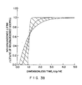
- Figure 3B shows the acceptable range for the tracer response in the effluent to guarantee Pe greater than 1 (i.e., plug flow behavior).
- Figure 4 shows D/U as a function of gas velocity for a 15 cm diameter by 5 meter tall non-reactive bubble column operating with HCS wax and titania particles.
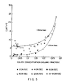
- Figure 5 shows D/U as a function of solids concentration for a 15 cm diameter non-reactive bubble column.
- Figure 6 shows the acceptable operating range in a slurry bubble column in D/U g L vs. (U s -U L )/U g parameter space.
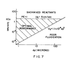
- Figure 7 shows the acceptable operating range for the Fischer-Tropsch catalyst/wax system in a slurry bubble column in D/U vs. catalyst diameter parameter space.
- the optimal operation of a slurry bubble column reactor requires that the solid phase be fluidized in the liquid phase over the entire height of the column.
- the solid phase is fluidized by upward forces caused by rising gas bubbles and acting against the tendency of the particles to settle under the downward gravitational force.
- the catalyst powders employed in this invention comprise a Group VIII metal such as iron, cobalt or ruthenium or mixtures thereof on an inorganic oxide support. These catalysts may contain additional promoters comprising Group I, Group II, Group V, or Group VII metals alone or in combination.
- the preferred catalyst powders of this invention comprise cobalt or cobalt and thoria on an inorganic oxide support containing a major amount of titania, silica or alumina.
- the catalyst may also contain a promoter metal, preferably rhenium, in an amount sufficient to provide a catalyst having a rhenium:cobalt weight ratio greater than about 0.01 to 1, preferably 0.025:1 to about 0.1 to 1.
- the catalyst contains about 2 to 50 wt% cobalt, preferably 5 to 20 wt% cobalt.
- the catalyst metals are supported on an inorganic refractory oxide comprising titania, silica or alumina.
- the support material is comprised of major amounts of titania and more preferably the titania has a rutile:anatase ratio of at least about 2:3 as determined by x-ray diffraction (ASTM D2730-78), preferably about 2:3 to about 100:1 or higher, more preferably about 4:1 to 100:1 or higher, e.g., 100% rutile.
- the surface area of the preferred support is, generally, less than about 50 m2/gm (BET).
- Cobalt-rhenium/titania catalysts exhibit high selectivity in the synthesis of hydrocarbon liquids from carbon monoxide and hydrogen.
- the catalysts employed in the practice of this invention may be prepared by techniques known in the art for the preparation of other catalysts.
- the catalyst powder can, e.g., be prepared by gellation, or cogellation techniques.
- the metals can be deposited on a previously pilled, pelleted, beaded, extruded, or sieved support material by the impregnation method.
- the metals are deposited from solution on the support in preselected amounts to provide the desired absolute amounts, and weight ratio of the respective metals, cobalt and rhenium.
- the cobalt and rhenium are composited with the support by contacting the support with a solution of a cobalt containing compound, or salt, or a rhenium-containing compound, or salt, e.g., a nitrate, carbonate or the like.
- a cobalt containing compound, or salt or a rhenium-containing compound, or salt, e.g., a nitrate, carbonate or the like.
- the cobalt and rhenium can be coimpregnated on the support.
- the cobalt and rhenium compounds used in the impregnation can be any organometallic or inorganic compounds which decompose upon heating in nitrogen, argon, helium or other inert gas, calcination in an oxygen containing gas, or treatment with hydrogen at elevated temperatures to give the corresponding metal, metal oxide, or mixtures of the metal and metal oxide phases, of cobalt and rhenium.
- Cobalt and rhenium compounds such as the nitrate, acetate, acetylacetonate, naphthenate, carbonyl, or the like can be used.
- the amount of impregnation solution should be sufficient to completely wet the carrier, usually within the range from about 1 to 20 times of the carrier by volume, depending on the metal, or metals, concentration in the impregnation solution.
- the impregnation treatment can be carried out under a wide range of conditions including ambient or elevated temperatures.
- the catalyst after impregnation, is dried by heating at a temperature above 30°C, preferably between 30°C and 125°C, in the presence of nitrogen, or oxygen, or both, or air, in a gas stream or under partial vacuum.
- the catalyst particles are converted to the desired particle size range of nominally 1-200 microns average diameter by crushing, ultrasonic treatment, or other methods known to those skilled in the art.
- the material can then be sieved, if necessary, to produce a powder that is predominantly within the desired particle size range.
- the slurry liquid used in the process is a liquid at the reaction temperature, must be relatively or largely or significantly chemically inert under the reaction conditions and must be a relatively good solvent for CO/hydrogen and possess good slurrying and dispersing properties for the finely divided catalyst.
- Representative classes of organic liquids which can be utilized are high boiling paraffins, olefins, aromatic hydrocarbons, alcohols, ethers, amines, or mixtures thereof.
- the high boiling paraffins include C10-C50 linear or branched paraffinic hydrocarbons; the olefins include poly ⁇ -olefin liquids; the aromatic hydrocarbons include C2-C20 single ring and multi and fused ring aromatic hydrocarbons; the ethers include aromatic ethers and substituted aromatic ethers where the ether oxygen is sterically hindered from being hydrogenated; the amines include long chain amines which can be primary, secondary, and tertiary amines, wherein primary amines preferably contain at least a C12 alkyl group in length, secondary amines preferably contain at least two alkyl groups being C7 or greater in length, and tertiary amines preferably contain at least three alkyl groups being C6 or higher in length.
- the slurry liquid can contain N and O in the molecular structure but not S, P, As or Sb, since these are poisons in the slurry process.
- Representative examples of specific liquid slurry solvents useful are dodecane, tetradecane, hexadecane, octadecane, cosane, tetracosane, octacosane, dotriacontane, hexatriacontane, tetracontane, tetratetracontane, toluene, o-, m-, and p-xylene, mesitylene, C1-C12 mono- and multi-alkyl substituted benzenes, dodecylbenzene, naphthalene, anthracene, biphenyl, diphenylether, dodecylamine, dinonylamine, trioctylamine, and the like.
- the improved process of the present invention can be applied to hydrogenation, aromatization, hydrodesulfurization, hydrodenitrogenation, resid hydroprocessing, hydroformylation and related reactions. These are described in more detail in "Applied Heterogenerous Catalysis", J. F. LePage et al, Editions Tecnip Paris (1987).
- the height to which the catalyst can be fluidized is given by D/(U s -U L ) where D is the dispersion coefficient for the particles, U s is the particle settling velocity (see Example 2) and U L is the liquid velocity along the column.
- D the dispersion coefficient for the particles
- U s the particle settling velocity (see Example 2)
- U L the liquid velocity along the column.
- the total reactor volume must be controlled to yield the desired conversion rate of reactants to products for the intrinsic catalyst activity. This normally sets a minimum height for the reaction zone (i.e., minimum liquid and fluidization height) for economic reactor operation. Also, while making the catalyst particles smaller improves the fluidization it also greatly increases the difficulty in separating them from the liquid product stream. Hence, catalyst particle diameters of less than 5 microns should be avoided. A more preferred diameter is greater than 30 microns.
- the required reactor volume is much less for the plug flow system at moderate or high conversions.
- a detailed model is available for calculating the effects of non-uniform catalyst distribution at intermediate mixing conditions for arbitrary kinetic expressions in specific applications.
- a given reactor generally exhibits behavior intermediate between plug-flow and well-mixed.
- U g is the average velocity of the gas along the reactor
- D the gas phase dispersion coefficient
- k the reaction rate constant.
- Example 3 Experimental Procedure to Determine the Dispersion in a Given Reactor
- Example 2 demonstrates the importance of the Peclet number in determining the reactor performance. While calculating or measuring the reaction zone height and the gas velocity is relatively straightforward, it is difficult to know a priori the dispersion coefficient. The dispersion coefficient depends on the gas throughput velocity as well as on the reactor geometry. As the reactor diameter is increased, the dispersion increases rapidly. The problem is complicated by the need to provide internal reactor structures within the reactor in order to improve heat removal. A general correlation for the dispersion coefficient as a function of geometric configuration is not possible because different internal configurations will produce different and poorly understood mixing patterns. In fact, the geometry of the internal design is the key factor the designer can use to control the mixing behavior of a slurry bubble column reactor for a given outside diameter and height that are determined by volume requirements (i.e., by requirements to achieve a desired conversion).
- the Peclet number of a given reactor can be determined from a tracer test for that reactor or a geometrically equivalent non-reactive mockup unit at milder but well defined conditions. Inert gas is fed to the bottom of the reactor and after allowing the system to equilibrate a small concentration of a tracer gas is added to the feed stream as a step function (cf. Figure 3A). Then by measuring the shape of the concentration profile of the tracer in the gas outlet stream, the Peclet number can be determined for the reactor by matching experimental results to model calculations.
- the Peclet number is the only parameter in this equation. For infinitely large Peclet numbers (i.e., plug-flow), the output is a delayed step function; and as the Pe number is decreased (backmixing increases), the output response is more spread out in time. If the response pulse falls outside of the shaded area in Figure 3B, the Peclet number is less than 1, and the reactor begins to give decreased conversion because of backmixing.
- Example 4 Catalyst Distribution as a Function of Gas Velocity
- the catalyst distribution is determined by a balance of gravitational settling of the particles and dispersion created by the upward flow of the gas bubbles. This balance results in a profile of the catalyst concentration, C particle , given by: where U s is the particle settling velocity, U L is the liquid velocity along the reactor, D is the dispersion coefficient of the liquid, x is the vertical distance from the bottom of the reactor, and A is a constant that depends on the total volumetric solids concentration in the reactor. The solids concentration decreases by a factor of 2.7 each time the height in the slurry increases by an amount equal to D/(U s -U L ).
- the solids distributions of glass beads and of titania particles in HCS wax were determined in a 6 ⁇ diameter non-reactive bubble column by taking samples from the vessel at 1 meter intervals.
- the temperature was 400°F and the pressure was 280 psig for gas velocities below 8 cm/sec and 150 psig for gas velocities above 8 cm/sec.
- the decay length was obtained by taking the slope of a line segment joining the data points when plotted as the logarithm of the solids concentration versus height. In Figure 5, the decay length in each zone is plotted versus the average concentration in the zone for superficial gas velocities of 2-16 cm/sec.
- c is the volume fraction of solids in the slurry
- U o is the Stokes settling velocity defined by where d p is the diameter of the particle, ⁇ s is the density of the particle, ⁇ l is the density of the suspending liquid, ⁇ is the viscosity of the liquid, and g is the gravitational constant. For velocities between 4 and 8 cm/sec a linear interpolation works well.
- Example 6 Method for Predicting Solids Distribution in a Slurry Bubble Column Reactor
- Example 5 allow one to predict the catalyst distribution in a slurry bubble column reactor via the following algorithm.
- the reactor is charged with n species of particles each of which has a Stokes settling velocity U i and average concentration C io .
- a given species may or may not be catalytic.
- the algorithm begins by guessing the values of all the c i 's at the bottom of the reactor and then the equations for the c i 's are integrated numerically until the top of the slurry is reached.
- the total predicted inventory for each solid species is compared to the known charge; i.e., we check that where E is the volume fraction of gas (i.e., the gas holdup) at height x and H is the height of the slurry.
- ⁇ s is the effective density of the particles (approximately 2.7 gr/cm3)
- ⁇ l is the density of the wax (0.7 gr/cm3)
- ⁇ is the viscosity of the wax (0.01 gr-cm/sec)
- g is the gravitational constant
- c is the volume fraction of solids in the slurry
- f(c) is 1 for a dilute slurry and a monotonic decreasing function of solids volume fraction at higher solids loading.
Abstract
Description
- The present invention relates to the optimal operation of a slurry bubble column reactor. Such columns have three phases in which solid catalyst particles are held in suspension in a liquid phase by bubbling gas phase reactants.
- Slurry bubble column reactors operate by suspending catalytic particles in a liquid and feeding gas phase reactants into the bottom of the reactor through a gas distributor which produces small gas bubbles. As the gas bubbles rise through the reactor, the reactants are absorbed into the liquid and diffuse to the catalyst where, depending on the catalytic system, they can be converted to both liquid and gaseous products. If gaseous products are formed, they enter the gas bubbles and are collected at the top of the reactor. Liquid products are recovered by passing the slurry through a filter which separates the liquid from the catalytic solids. A principal advantage of slurry reactors over fixed bed reactors is that the presence of a circulating/agitated slurry phase greatly increases the transfer rate of heat to cooling surfaces built into the reactor. Because reactions of interest are often highly exothermic, this results in reduced reactor cost (less heat transfer equipment is needed) and improved stability during reactor operations. A distinct advantage of bubble columns over mechanically stirred reactors is that the required mixing is effected by the action of rising bubbles, a process significantly more energy-efficient than mechanical stirring.
- In any reaction, the rate of conversion of reactants to products and the product selectivity depend on the partial pressure of the reactants in contact with the catalyst. Thus, the mixing characteristics of the reactor become critical in determining catalyst performance because they will determine the gas phase composition (and therefore, the partial pressure of the reactants) at any particular axial position in the reactor.
- In fully backmixed reactors (CSTR), the composition of reactants (gaseous) and products (liquids and gases) and condition of the catalyst is identical at every point within the reactor. The reactant concentration (or gas partial pressure) controls catalyst performance by providing the driving force for the reaction and determines the conversion occurring in the reactor. Thus, even though pure reactant feed is entering the reactor, catalyst performance is driven by the uniform reactant gas phase concentration present throughout the reactor and equal to the reactant gas phase concentration exiting the reactor. This fully backmixed system has a low relative productivity per volume of reactor for any reactions having positive pressure order rate kinetics.
- The other extreme in reactor mixing occurs in plug flow reactors where the catalyst is stationary relative to the flow of reactants and products (liquids and gases). The feed undergoes reaction as it enters the reactor and the reaction continues as the unreacted feed proceeds through the reactor. Thus, the concentration and partial pressure of reactants decrease along the path of the reactor; therefore, the driving force of the reaction also decreases as the concentration of liquid and gaseous products increase. Thus, the catalyst at the exit portion of the plug flow reactor never sees fresh feed. The plug flow system provides maximum productivity for a given reactor volume for any reactions showing positive pressure order kinetics.
- The important difference between the CSTR and plug flow reactor systems is that the gas phase reactant concentrations that provide the kinetic driving force for the reaction differ significantly. In the fully backmixed system, the reactant concentration is the same at every point in the reactor; in the plug flow system, the reactant concentration steadily decreases along the path of the catalyst bed from inlet to outlet and the reaction rate is obtained by integrating the rate function from inlet to outlet. Because the reactant concentration at any point in a CSTR system always corresponds to outlet conditions, the productivity in a fully backmixed system will always be lower than the productivity in a plug-flow system for reactions with positive pressure order kinetics.
- Reactor systems exhibiting plug-flow and well stirred characteristics represent extremes in reactor performance. In practice, plug-flow reactors may exhibit some backmixed traits and backmixed reactors may exhibit some plug-flow traits. Deviations from the ideal systems are due to the dispersion of the reactant gases in the reactor. Extent of backmixing is a function of the mechanical energy imparted to the system. The reactor geometry also affects backmixing and small L/d (i.e., reactor length to reactor diameter) ratios, less than 3, favor complete backmixing. However, higher energy input reactors with greater L/d can also achieve complete backmixing. Conversely, plug-flow behavior is favored by high L/d ratios. The degree of backmixing that can occur in a plug-flow reactor can be represented by the Peclet number, Pe, which is equal to LUg/D, where L is the reactor length, Ug is the average gas velocity along the reactor, and D is the dispersion coefficient for a given reactor configuration and operating conditions. (See Carberry, J.J., "Chemical and Catalytic Reaction Engineering", McGraw-Hill, 1976, or Levenspiel, O., "Chemical Reaction Engineering", Wiley, 1972.)
- High Peclet numbers, e.g., greater than 10, lead to plug-flow behavior while low Peclet numbers, e.g., less than 1, correspond to well-mixed systems and are typical of CSTR's. By definition, the dispersion coefficient for an ideal CSTR is infinity and the Peclet number approaches zero.
- These considerations show that the scale-up of slurry reactors from laboratory to commercial units is not straightforward. For example, as the reactor vessel is made taller, the height to which the catalyst is fluidized is likely not to increase proportionally or at all, and the added reactor volume remains unused. Also, as the reactor diameter increases, the mixing intensity increases and may result in an increase in the fluidization height but could also increase the Peclet number and move the reactor performance from plug-flow to well-mixed with a corresponding decrease in conversion of products to reactants.
- This difficulty is obvious in previous attempts to apply slurry reactors to the important process of Fischer-Tropsch synthesis of hydrocarbons (predominantly C₁₀+) from synthesis gas (carbon monoxide and hydrogen) using iron catalysts. The sole previous scale-up efforts reported in the literature for commercial size units (5 ft. diameter) were the Rheinpreussen tests in the 1950's (see H. Storch, N. Columbis, R.B. Anderson, "Fischer-Tropsch and Related Synthesis", Wiley (1951) New York and J. Falbe, "Advances in Fischer-Tropsch Catalysis", Verlag (1977) Berlin). Moving from laboratory to commercial units, they sequentially built systems in which the dispersion was too low to adequately fluidize the particles to systems with dispersions high enough to cause backmixed reactor behavior in the commercial size reactor. To date, the optimal implementation of large scale systems has not been achieved or described. A methodology for such a scale-up process is described in this invention.
- Optimum performance of slurry bubble column reactors requires adequate fluidization of the catalyst particles while minimizing backmixing of the reactants in the gas phase. If the conditions in the reactor are such that the particles settle, difficulties arise because the reaction zone is short. Then in order to achieve high conversions, the reaction rate per volume must be very high and the catalyst can easily become starved of reactants because of limitations in the rate at which reactants can be transferred from the gas bubbles to the particles suspended in the liquid. This condition results in poor catalyst utilization, poor reaction selectivity, and eventually to catalyst deactivation. Also, for exothermic reactions, the heat release takes place in the short reaction zone, imposing severe requirements on the heat transfer equipment.
- The tendency of the particles to settle can be overcome, however, by maximizing the dispersion effects resulting from the rising gas bubbles and from the mixing patterns that they induce. These dispersion effects can be enhanced by increasing either the effective reactor diameter or the flow rate of gas through the reactor. If the dispersion is increased too much, however, the gas phase will also become well mixed and the reactor performance will change from that of a plug flow reactor to that of a backmixed reactor.
- Eri et al in U.S. Patent 4,857,559 have discussed the relative merits of operating a Fischer-Tropsch reactor with a feed gas containing various levels of diluents such as methane, carbon dioxide, and nitrogen. In fixed bed reactors, they have indicated that the presence of a diluent such as nitrogen in the feed is disadvantageous since it will increase the pressure drop across the reactor bed. In a slurry or fluidized bed reactor they indicate that diluent has beneficial effects, in that it provides additional mixing energy to the system to keep the catalyst suspended. Moreover they note that added diluent will not have a great effect on pressure drop in the slurry or fluidized bed reactors.
- Eri et al also indicated that diluents will have a disadvantageous effect on the fixed bed reactor since it will, at constant overall pressure, lead to a net reduction in the partial pressure of reactant gases present with a concomitant net reduction in the overall volumetric productivity of the system. They failed to indicate, however, that a similar reduction in productivity would result in slurry or fluidized bed reactors as the diluent reduces the reactant gas partial pressure. Consequently, the improved catalyst fluidization achieved with added diluent is offset by the reduced productivity and subsequent diluent processing steps associated with product recovery.
- The preferred embodiment of the present invention is the Fischer-Tropsch synthesis of hydrocarbons using CO catalysts. The Fischer-Tropsch reaction involves the catalytic hydrogenation of carbon monoxide to produce a variety of products ranging from methane to higher aliphatic alcohols. The methanation reaction was first described by Sabatier and Senderens in 1902. The later work by Fischer and Tropsch dealing with higher hydrocarbon synthesis was described in Brennstoff-Chem, 7, 97 (1926).
- The reaction is highly exothermic and care must be taken to design reactors for adequate heat exchange capacity as well as for their the ability to continuously produce and remove the desired range of hydrocarbon products. The process has been considered for the conversion of carbonaceous feedstocks, e.g., coal or natural gas, to higher value liquid fuel or petrochemicals. The first major commercial use of the Fischer-Tropsch process was in Germany during the 1930's. More than 10,000 B/D of products were manufactured with a cobalt based catalyst in a fixed-bed reactor. This work has been described by Fischer and Pichler in Ger. Pat. No. 731,295 issued August 2, 1936.
- Commercial practice of the Fischer-Tropsch process has continued in South Africa in the SASOL plants. These plants use iron based catalysts and produce gasoline in fluid-bed reactor and wax in fixed-bed reactors.
- Research aimed at the development of more efficient CO hydrogenation catalysts and reactor systems is continuing. In particular, a number of studies describe the behavior of iron, cobalt or ruthenium based catalysts in slurry reactors together with the development of catalyst compositions and improved pretreatment methods specifically tailored for that mode of operation.
- Farley et al in The Institute of Petroleum, vol. 50, No. 482, pp. 27-46, February (1984), describe the design and operation of a pilot-scale slurry reactor for hydrocarbon synthesis. Their catalysts consisted of precipitated iron oxide incorporating small amounts of potassium and copper oxides as promoters. These catalysts underwent both chemical and physical changes during activation with synthesis gas in the slurry reactor.
- Slegeir et al in Prepr. ACS Div. Fuel Chem, vol. 27, p. 157-163 (1982), describe the use of supported cobalt catalysts for the production of hydrocarbons from synthesis gas at pressures above 500 psi in a CSTR slurry reactor.
- Rice et al in US 4,659,681 issued on April 21, 1987, describe the laser synthesis of iron based catalyst particles in the 1-100 micron particle size range for use in a slurry Fischer-Tropsch reactor.
- Dyer et al in US 4,619,910 issued on October 28, 1986, and US 4,670,472 issued on June 2, 1987, and US 4,681,867 issued on July 21, 1987, describe a series of catalysts for use in a slurry Fischer-Tropsch process in which synthesis gas is selectively converted to higher hydrocarbons of relatively narrow carbon number range. Reactions of the catalyst with air and water and calcination are specifically avoided in the catalyst preparation procedure. Their catalysts are activated in a fixed-bed reactor by reaction with CO + H₂ prior to slurrying in the oil phase in the absence of air.
- Fujimoto et al in Bull. Chem. Soc. Japan, vol. 60, pp. 2237-2243 (1987), discuss the behavior of supported ruthenium catalysts in slurry Fischer-Tropsch synthesis. They indicate that the catalyst precursors were ground to fine powders (< 150 Tyler mesh), calcined if needed, and then activated in flowing hydrogen before addition to a degassed solvent and subsequent introduction to the slurry reactor.
- The present invention is a method for optimally designing and operating a three-phase slurry bubble column reactor. The constituents of the three phases, gas, liquid, and solids, are defined by the desired chemical reaction. The method includes injecting the gas phase into a column of a given diameter in such a way as to provide the substantial absence of slug flow and with an appropriate velocity so that the solid phase is fluidized while still maintaining "plug flow" reactor behavior over the column length.
- Figure 1 shows a comparison of the volume needed for plug-flow and well-mixed reactors in order to achieve a given conversion.
- Figure 2 shows a comparison of the reactor volume required to achieve different degrees of conversion of reactant to product as a function of degree of backmixing.
- Figure 3A shows a schematic diagram of a tracer test configuration designed to determine the extent of backmixing in a bubble column reactor.
- Figure 3B shows the acceptable range for the tracer response in the effluent to guarantee Pe greater than 1 (i.e., plug flow behavior).
- Figure 4 shows D/U as a function of gas velocity for a 15 cm diameter by 5 meter tall non-reactive bubble column operating with HCS wax and titania particles.
- Figure 5 shows D/U as a function of solids concentration for a 15 cm diameter non-reactive bubble column.
- Figure 6 shows the acceptable operating range in a slurry bubble column in D/UgL vs. (Us-UL)/Ug parameter space.
- Figure 7 shows the acceptable operating range for the Fischer-Tropsch catalyst/wax system in a slurry bubble column in D/U vs. catalyst diameter parameter space.
- The optimal operation of a slurry bubble column reactor requires that the solid phase be fluidized in the liquid phase over the entire height of the column. The solid phase is fluidized by upward forces caused by rising gas bubbles and acting against the tendency of the particles to settle under the downward gravitational force.
- Generally, the catalyst powders employed in this invention comprise a Group VIII metal such as iron, cobalt or ruthenium or mixtures thereof on an inorganic oxide support. These catalysts may contain additional promoters comprising Group I, Group II, Group V, or Group VII metals alone or in combination. The preferred catalyst powders of this invention comprise cobalt or cobalt and thoria on an inorganic oxide support containing a major amount of titania, silica or alumina. The catalyst may also contain a promoter metal, preferably rhenium, in an amount sufficient to provide a catalyst having a rhenium:cobalt weight ratio greater than about 0.01 to 1, preferably 0.025:1 to about 0.1 to 1. The catalyst contains about 2 to 50 wt% cobalt, preferably 5 to 20 wt% cobalt.
- The catalyst metals are supported on an inorganic refractory oxide comprising titania, silica or alumina. Preferably, the support material is comprised of major amounts of titania and more preferably the titania has a rutile:anatase ratio of at least about 2:3 as determined by x-ray diffraction (ASTM D2730-78), preferably about 2:3 to about 100:1 or higher, more preferably about 4:1 to 100:1 or higher, e.g., 100% rutile. The surface area of the preferred support is, generally, less than about 50 m²/gm (BET).
- Cobalt-rhenium/titania catalysts exhibit high selectivity in the synthesis of hydrocarbon liquids from carbon monoxide and hydrogen. The catalysts employed in the practice of this invention may be prepared by techniques known in the art for the preparation of other catalysts. The catalyst powder can, e.g., be prepared by gellation, or cogellation techniques. Suitably, however, the metals can be deposited on a previously pilled, pelleted, beaded, extruded, or sieved support material by the impregnation method. In preparing catalysts, the metals are deposited from solution on the support in preselected amounts to provide the desired absolute amounts, and weight ratio of the respective metals, cobalt and rhenium. Suitably, the cobalt and rhenium are composited with the support by contacting the support with a solution of a cobalt containing compound, or salt, or a rhenium-containing compound, or salt, e.g., a nitrate, carbonate or the like. Optionally, the cobalt and rhenium can be coimpregnated on the support. The cobalt and rhenium compounds used in the impregnation can be any organometallic or inorganic compounds which decompose upon heating in nitrogen, argon, helium or other inert gas, calcination in an oxygen containing gas, or treatment with hydrogen at elevated temperatures to give the corresponding metal, metal oxide, or mixtures of the metal and metal oxide phases, of cobalt and rhenium. Cobalt and rhenium compounds such as the nitrate, acetate, acetylacetonate, naphthenate, carbonyl, or the like can be used. The amount of impregnation solution should be sufficient to completely wet the carrier, usually within the range from about 1 to 20 times of the carrier by volume, depending on the metal, or metals, concentration in the impregnation solution. The impregnation treatment can be carried out under a wide range of conditions including ambient or elevated temperatures.
- The catalyst, after impregnation, is dried by heating at a temperature above 30°C, preferably between 30°C and 125°C, in the presence of nitrogen, or oxygen, or both, or air, in a gas stream or under partial vacuum.
- The catalyst particles, if necessary, are converted to the desired particle size range of nominally 1-200 microns average diameter by crushing, ultrasonic treatment, or other methods known to those skilled in the art. The material can then be sieved, if necessary, to produce a powder that is predominantly within the desired particle size range.
- The slurry liquid used in the process is a liquid at the reaction temperature, must be relatively or largely or significantly chemically inert under the reaction conditions and must be a relatively good solvent for CO/hydrogen and possess good slurrying and dispersing properties for the finely divided catalyst. Representative classes of organic liquids which can be utilized are high boiling paraffins, olefins, aromatic hydrocarbons, alcohols, ethers, amines, or mixtures thereof. The high boiling paraffins include C₁₀-C₅₀ linear or branched paraffinic hydrocarbons; the olefins include poly α-olefin liquids; the aromatic hydrocarbons include C₂-C₂₀ single ring and multi and fused ring aromatic hydrocarbons; the ethers include aromatic ethers and substituted aromatic ethers where the ether oxygen is sterically hindered from being hydrogenated; the amines include long chain amines which can be primary, secondary, and tertiary amines, wherein primary amines preferably contain at least a C₁₂ alkyl group in length, secondary amines preferably contain at least two alkyl groups being C₇ or greater in length, and tertiary amines preferably contain at least three alkyl groups being C₆ or higher in length. The slurry liquid can contain N and O in the molecular structure but not S, P, As or Sb, since these are poisons in the slurry process. Representative examples of specific liquid slurry solvents useful are dodecane, tetradecane, hexadecane, octadecane, cosane, tetracosane, octacosane, dotriacontane, hexatriacontane, tetracontane, tetratetracontane, toluene, o-, m-, and p-xylene, mesitylene, C₁-C₁₂ mono- and multi-alkyl substituted benzenes, dodecylbenzene, naphthalene, anthracene, biphenyl, diphenylether, dodecylamine, dinonylamine, trioctylamine, and the like. Preferred liquid hydrocarbon slurry solvent is octacosane or hexadecane. (Most preferred really is HCS wax, i.e., the product of the FT reaction.)
- In addition to CO hydrogenation, the improved process of the present invention can be applied to hydrogenation, aromatization, hydrodesulfurization, hydrodenitrogenation, resid hydroprocessing, hydroformylation and related reactions. These are described in more detail in "Applied Heterogenerous Catalysis", J. F. LePage et al, Editions Tecnip Paris (1987).
- The height to which the catalyst can be fluidized is given by D/(Us-UL) where D is the dispersion coefficient for the particles, Us is the particle settling velocity (see Example 2) and UL is the liquid velocity along the column. This liquid flow along the column may be produced by removing liquid from the top of the reactor at a rate equal to the liquid product production rate plus any extra liquid which is injected back into the bottom of the reactor as liquid recycle. While such liquid recycle can enhance the fluidization height it is usually an undesirable operating mode because the pumps and added filters greatly add to the construction and operating costs and to the complexity of operating procedures of the reactor. If this fluidization height exceeds the actual physical height of the reactor, the catalyst concentration becomes more uniform than is necessary for efficient operation. Hence, excellent reactor performance can be achieved when the reactor is designed and the operating conditions are picked such that H = D/(Us-UL) or D = H(Us-UL), where H is the expanded height of the liquid in the column.
- This ability to fluidize the particles arises from mixing induced by the gas bubbles and, therefore, at the expense of some backmixing of the reactants. Plug-flow behavior can still be achieved, however, because for gas mixing the importance of the dispersion must be compared to Ug, the gas velocity, rather than to the particle settling velocity Us. Specifically, the degree of backmixing of the gas is measured by the Peclet number, defined by Pe = UgH/D. If the dispersion is maintained at that just required to fluidize the particles (i.e., if the reactor conditions are such that D ≃ 0.5H(Us-UL), then Pe = Ug/(Us-UL) >> 1 and plug flow behavior will prevail. In practical terms, this requires a design with intermediate values of the reactor diameter and gas velocity. Low particle settling velocities increase the window of acceptable operating parameters but is not by itself a necessary condition for good performance (see Example 7).
- It is the object of the present invention to avoid the need for substantial quantities of diluent in the reactant feed gas stream, while simultaneously operating with a well suspended catalyst bed in a plug flow mode. This will not only lead to substantially higher productivity per unit volume of reactor space, but also eliminate the need to first produce and then separate diluent from products and various reactant gas recycle streams. All of these factors lead to energy and investment savings, thereby improving the overall economic attractiveness of the process.
- While these are the primary constraints for efficient reactor performance, there are auxillary conditions important in scale-up. For example, the total reactor volume must be controlled to yield the desired conversion rate of reactants to products for the intrinsic catalyst activity. This normally sets a minimum height for the reaction zone (i.e., minimum liquid and fluidization height) for economic reactor operation. Also, while making the catalyst particles smaller improves the fluidization it also greatly increases the difficulty in separating them from the liquid product stream. Hence, catalyst particle diameters of less than 5 microns should be avoided. A more preferred diameter is greater than 30 microns. Finally, if the effective reactor diameter is too small, the flow regime has large gas slugs (i.e., slug flow) rising through the column rather than a dispersion of small gas bubbles typical of bubbly or chrun turbulent flow which give better mass transfer performance. Hence, bubble column diameters of less than 10 cm should not be used for either obtaining data for scaleup or for commercial units (see Gas-Liquid-Solid Fluidization Engineering, Liang-Shih Fan, Butterworths, Boston (1989)). Reactors with small effective diameters also can lead to unreasonable complexity and construction cost when designed for systems large enough to convert commercial feed rates of reactants.
- For isothermal reactors with constant catalyst density being supplied with reactant at a volumetric rate F, the reactor volume (V) required for a given exit concentration or conversion is:


where
Xe is the exit conversion
R is the reaction rate
C is the concentration
Co is the inlet concentration. - Assuming first order kinetics (the HCS reaction order in total pressure is about 0.7), we find:


- As shown in Figure 1, the required reactor volume is much less for the plug flow system at moderate or high conversions. A detailed model is available for calculating the effects of non-uniform catalyst distribution at intermediate mixing conditions for arbitrary kinetic expressions in specific applications.
- A given reactor generally exhibits behavior intermediate between plug-flow and well-mixed. For reaction rates that are first order in the concentration of reactants, the reactant concentration at any position along the reactor can be determined by solving the convection-diffusion equation:


- This model can be solved to determine the reactor volume necessary for a given conversion as a function of Peclet number. The results are plotted in Figure 2. If the Peclet number is above 10, we see that effectively plug flow behavior is achieved and that the reactor volume requirements become independent of Peclet number.
- Example 2 demonstrates the importance of the Peclet number in determining the reactor performance. While calculating or measuring the reaction zone height and the gas velocity is relatively straightforward, it is difficult to know a priori the dispersion coefficient. The dispersion coefficient depends on the gas throughput velocity as well as on the reactor geometry. As the reactor diameter is increased, the dispersion increases rapidly. The problem is complicated by the need to provide internal reactor structures within the reactor in order to improve heat removal. A general correlation for the dispersion coefficient as a function of geometric configuration is not possible because different internal configurations will produce different and poorly understood mixing patterns. In fact, the geometry of the internal design is the key factor the designer can use to control the mixing behavior of a slurry bubble column reactor for a given outside diameter and height that are determined by volume requirements (i.e., by requirements to achieve a desired conversion).
- The Peclet number of a given reactor can be determined from a tracer test for that reactor or a geometrically equivalent non-reactive mockup unit at milder but well defined conditions. Inert gas is fed to the bottom of the reactor and after allowing the system to equilibrate a small concentration of a tracer gas is added to the feed stream as a step function (cf. Figure 3A). Then by measuring the shape of the concentration profile of the tracer in the gas outlet stream, the Peclet number can be determined for the reactor by matching experimental results to model calculations.
- The model describing this test using a tracer that is insoluble in the liquid is:

- The same tests can be performed using a soluble tracer, but the required model and its interpretation of results are more complicated. The required procedure is obvious to those knowledgeable of the art and can yield additional information not germane to this invention.
- The catalyst distribution is determined by a balance of gravitational settling of the particles and dispersion created by the upward flow of the gas bubbles. This balance results in a profile of the catalyst concentration, Cparticle, given by:

- The solids distributions of glass beads and of titania particles in HCS wax were determined in a 6˝ diameter non-reactive bubble column by taking samples from the vessel at 1 meter intervals. The temperature was 400°F and the pressure was 280 psig for gas velocities below 8 cm/sec and 150 psig for gas velocities above 8 cm/sec. The decay length was obtained by taking the slope of a line segment joining the data points when plotted as the logarithm of the solids concentration versus height. In Figure 5, the decay length in each zone is plotted versus the average concentration in the zone for superficial gas velocities of 2-16 cm/sec.
- The data can be correlated reasonably by:
D/Us (feet) = 0.2(1+20c²+3000c⁴)/Uo(cm/sec) for Ug < 4 cm/sec
D/Us (feet) = 1.2(1+3c²+550c⁴)/Uo(cm/sec) for Ug > 8 cm/sec
where c is the volume fraction of solids in the slurry and Uo is the Stokes settling velocity defined by
- This demonstrates a marked increase in the fluidization height when the solids loading is increased above 20%. Most of this increase is due to a reduction in the particle settling velocity as the solids concentration increases (see R. H. Davis and A. Acrivos, Annual Review of Fluid Mechanics 17, 91, 1985).
- The data of Example 5 allow one to predict the catalyst distribution in a slurry bubble column reactor via the following algorithm. Suppose the reactor is charged with n species of particles each of which has a Stokes settling velocity Ui and average concentration Cio. A given species may or may not be catalytic. The concentration of each species must satisfy the differential equation

- The algorithm begins by guessing the values of all the ci's at the bottom of the reactor and then the equations for the ci's are integrated numerically until the top of the slurry is reached. The gas velocity is computed by requiring a given overall conversion, X, and assuming the extent of reaction at any height is proportional to the fraction of the total catalyst inventory below that height; thus

- When the integration reaches the top of the slurry, the total predicted inventory for each solid species is compared to the known charge; i.e., we check that

where E is the volume fraction of gas (i.e., the gas holdup) at height x and H is the height of the slurry. - If these equalities are not satisfied, the assumed concentrations at the bottom of the reactor were not correct and they are adjusted using a Newton-Raphson iteration technique. The equations are then integrated starting from the new values and the iterations are continued until convergence is obtained.
- This procedure can be easily extended to include the use of liquid flow along the reactor. The right hand side of the above equations are modified by subtracting the liquid velocity from the settling velocity of species i.
- As pointed out above, the dispersion coefficient should be large enough to fluidize the particles adequately over the height of the reactor, e.g.:

but small enough that the gas flow remains plug flow, e.g.:


- Hence for optimum performance, the reactor geometry and operating conditions must be chosen such that they lie within the shaded triangle shown in Figure 6.
- For the catalyst/wax system being considered, the Reynolds number for the settling particles is small and Us is given by Stokes law times a monotonically decreasing function [f(c)] which varies between 1 and 0 as the volume fraction of catalyst in the slurry is increased from 0 to the concentration at maximum packing. This "hindred settling function", is described in R. H. Davis and A. Acrivos, Annual Review of Fluid Mechanics 17 (1985). Hence, for the catalytic system of greatest interest

where dp is the particle diameter, ρs is the effective density of the particles (approximately 2.7 gr/cm³), ρℓ is the density of the wax (0.7 gr/cm³), µ is the viscosity of the wax (0.01 gr-cm/sec), g is the gravitational constant, c is the volume fraction of solids in the slurry, and f(c) is 1 for a dilute slurry and a monotonic decreasing function of solids volume fraction at higher solids loading. Hence, for our system:
- It is clear that while the D/H design range is quite broad for small particles because of our ability to fluidize such particles without extensive backmixing, this range narrows significantly for larger particles. Particles with greater than 100 µm diameters cannot be effectively fluidized without a backmixing debit on the kinetic driving force. Practical restrictions on the size of catalyst particles that can be effectively separated from the liquid medium by filtering, decantation, or other methods considerably narrow the allowable range of particle sizes and therefore design D/H parameters.
Claims (10)
- A method for optimally operating a three phase slurry bubble column in which solid particles are fluidized in the liquid phase by bubbles of the gas phase, comprising:(a) injecting the gas phase into said column such that the average gas velocity along said columns, Ug in the substantial absence of slug flow;(b) fluidizing the solid phase of solid particles of average diameter, dp, in the liquid phase, wherein the settling velocity of said solid particles in said liquid phase is:

 (c) maintaining plug flow in said column by said gas phase whose velocity:
 wherein ρs = effective density of the particlesρℓ = density of the liquidµ = viscosity of the liquidf(c) = hindered settling functionc = volume fraction of solids in the slurry (liquid plus solids)UL = liquid velocity along the columnH = height of the expanded liquid of said reactor
 - The method of claim 1 wherein said solid particles include a catalyst suitable for hydrogenation of CO.
- The method of claim 1 or claim 2 wherein said liquid is hydrocarbon synthesis wax, said solid is a catalyst suitable for the synthesis of such wax at typical Fischer-Tropsch conditions, and Us = 1.1 x 10⁻⁴d

- The method of any one of claims 1 to 3 wherein said gas velocity, Ug ≧ 1 H/D (e.g., Ug ≧ 10 H/D).
- The method of any one of claims 1 to 4 wherein said (catalyst) particles have a diameter greater than 5 microns (5 nm), e.g., a diameter greater than 30 microns (30 nm).
- The method of any one of claims 1 to 5 wherein H is greater than 3 meters.
- The method of any one of claims 1 to 6 wherein said height, H, includes at least 95% of the catalyst on which the catalyst reaction occurs.
- The method of any one of claims 1 to 7 wherein UL ≦ 1/2 Us, e.g., UL ≦ 0.5 cm/second.
- The method of any one of claims 1 to 8 wherein UL is determined in the absence of liquid recycle.
- The method of any one of claims 1 to 10 wherein said diameter of the reactor is greater than 5 cm.
Applications Claiming Priority (2)
| Application Number | Priority Date | Filing Date | Title |
|---|---|---|---|
| US50474690A | 1990-04-04 | 1990-04-04 | |
| US504746 | 1990-04-04 |
Publications (4)
| Publication Number | Publication Date |
|---|---|
| EP0450860A2 true EP0450860A2 (en) | 1991-10-09 |
| EP0450860A3 EP0450860A3 (en) | 1992-03-18 |
| EP0450860B1 EP0450860B1 (en) | 1994-10-05 |
| EP0450860B2 EP0450860B2 (en) | 2005-04-20 |
Family
ID=24007560
Family Applications (1)
| Application Number | Title | Priority Date | Filing Date |
|---|---|---|---|
| EP91302710A Expired - Lifetime EP0450860B2 (en) | 1990-04-04 | 1991-03-27 | Method of operating a slurry bubble column |
Country Status (7)
| Country | Link |
|---|---|
| US (1) | USRE39073E1 (en) |
| EP (1) | EP0450860B2 (en) |
| AU (1) | AU632413B2 (en) |
| CA (1) | CA2038774C (en) |
| DE (1) | DE69104400T3 (en) |
| MY (1) | MY107587A (en) |
| NO (1) | NO180001C (en) |
Cited By (19)
| Publication number | Priority date | Publication date | Assignee | Title |
|---|---|---|---|---|
| WO1993016796A1 (en) * | 1992-02-25 | 1993-09-02 | Den Norske Stats Oljeselskap A.S. | Method of conducting catalytic converter multi-phase reaction |
| WO1993016795A1 (en) * | 1992-02-25 | 1993-09-02 | Den Norske Stats Oljeselskap A.S. | Catalytic multi-phase reactor |
| WO1994016807A1 (en) * | 1993-01-28 | 1994-08-04 | Den Norske Stats Oljeselskap A.S. | Solid/liquid slurry treatment apparatus and catalytic multi-phase reactor |
| US5520890A (en) * | 1993-08-24 | 1996-05-28 | Den Norske Stats Oljeselskap A.S | Solid/liquid slurry treatment apparatus and catalytic multi-phase reactor |
| US5599849A (en) * | 1993-01-27 | 1997-02-04 | Sasol Chemical Industries (Proprietary) Limited | Process for producing liquid and, optionally, gaseous products from gaseous reactants |
| EP0823470A1 (en) * | 1996-08-07 | 1998-02-11 | AGIP PETROLI S.p.A. | Fischer-tropsch process with a multistage bubble culumn reactor |
| EP0824961A1 (en) | 1996-08-23 | 1998-02-25 | Shell Internationale Researchmaatschappij B.V. | Gas sparger for a suspension reactor and use thereof |
| WO1998027181A1 (en) * | 1996-12-16 | 1998-06-25 | Rentech, Inc. | Catalyst/wax separation device for slurry fischer-tropsch reactor |
| US6069179A (en) * | 1993-02-24 | 2000-05-30 | Den Norske Stats Oljeselskap As | Method of conducting catalytic converter multi-phase reaction |
| EP1061115A1 (en) * | 1999-06-17 | 2000-12-20 | ENI S.p.A. | Improved fischer-tropsch process |
| WO2005092824A1 (en) * | 2004-03-18 | 2005-10-06 | Conocophillips Company | Optimized particle distribution for slurry bubble column reactors |
| WO2007069317A1 (en) | 2005-12-14 | 2007-06-21 | Nippon Steel Engineering Co., Ltd. | Fischer-tropsch synthesis system using bubble column type slurry-bed reactor |
| EP1852182A1 (en) * | 2006-05-01 | 2007-11-07 | Engelhard Corporation | Fischer-Tropsch Catalyst comprising cobalt and zinc oxide |
| EP1947160A2 (en) | 2006-12-20 | 2008-07-23 | Ifp | Method for converting biomass for the production of synthetic gas |
| EP1268712B2 (en) † | 2000-04-04 | 2009-06-10 | ExxonMobil Research and Engineering Company | Process for softening fischer-tropsch wax with mild hydrotreating |
| US7772291B2 (en) | 2004-05-10 | 2010-08-10 | Sasol Technology (Proprietary) Limited | Production of liquid and, optionally, gaseous hydrocarbons from gaseous reactants into an expanded slurry bed |
| US7956018B2 (en) | 2007-12-10 | 2011-06-07 | Chevron U.S.A. Inc. | Lubricant composition |
| WO2012168829A1 (en) | 2011-06-07 | 2012-12-13 | Sasol Technology (Proprietary) Limited | Process for producing at least one product from at least one gaseous reactant in a slurry bed |
| WO2012168830A1 (en) | 2011-06-07 | 2012-12-13 | Sasol Technology (Proprietary) Limited | Process for producing at least one product from at least one gaseous reactant in a slurry bed |
Families Citing this family (20)
| Publication number | Priority date | Publication date | Assignee | Title |
|---|---|---|---|---|
| FR2806642B1 (en) | 2000-03-27 | 2002-08-23 | Inst Francais Du Petrole | PROCESS FOR CONVERTING HYDROCARBONS IN A THREE-PHASE REACTOR |
| GB2410449B (en) * | 2004-01-28 | 2008-05-21 | Statoil Asa | Fischer-Tropsch catalysts |
| DE102006015541A1 (en) * | 2006-03-31 | 2007-10-04 | List Holding Ag | Process for treating highly viscous products, comprises adding monomers, catalysts and/or initiators to a mixing kneader, heating the obtained product to a boiling temperature, and absorbing exothermicity of the product |
| US7271201B1 (en) | 2006-08-07 | 2007-09-18 | Syntroleum Corporation | Use of waste heat from Fischer-Tropsch synthesis to form dry pulverized fuel feedstock |
| GB2446127A (en) * | 2007-01-30 | 2008-08-06 | Gtl F1 Ag | Preparation of Fischer-Tropsch Catalysts |
| US20090005275A1 (en) * | 2007-06-28 | 2009-01-01 | Chevron U.S.A. Inc. | Power steering fluid |
| GB2473071B (en) | 2009-09-01 | 2013-09-11 | Gtl F1 Ag | Fischer-tropsch catalysts |
| US8349776B2 (en) * | 2009-09-29 | 2013-01-08 | Chevron Oronite Company Llc | Trunk piston engine lubricating oil compositions |
| GB2475492B (en) | 2009-11-18 | 2014-12-31 | Gtl F1 Ag | Fischer-Tropsch synthesis |
| PL2603316T3 (en) | 2010-08-09 | 2018-02-28 | Gtl. F1 Ag | Fischer-tropsch catalysts |
| US20120144887A1 (en) | 2010-12-13 | 2012-06-14 | Accelergy Corporation | Integrated Coal To Liquids Process And System With Co2 Mitigation Using Algal Biomass |
| US8702968B2 (en) | 2011-04-05 | 2014-04-22 | Chevron Oronite Technology B.V. | Low viscosity marine cylinder lubricating oil compositions |
| US9234139B2 (en) | 2011-11-01 | 2016-01-12 | Accelergy Corporation | Diesel fuel production process employing direct and indirect coal liquefaction |
| US9206374B2 (en) | 2011-12-16 | 2015-12-08 | Chevron Oronite Sas | Trunk piston engine lubricating oil compositions |
| CN105517983B (en) * | 2013-08-26 | 2018-08-10 | 国际壳牌研究有限公司 | The method for preparing glycols |
| SG10201710483WA (en) | 2013-11-06 | 2018-02-27 | Chevron Oronite Tech Bv | Marine diesel cylinder lubricant oil compositions |
| EP3066180B1 (en) | 2013-11-06 | 2021-01-13 | Chevron Oronite Technology B.V. | Marine diesel cylinder lubricant oil compositions |
| US9358526B2 (en) | 2013-11-19 | 2016-06-07 | Emerging Fuels Technology, Inc. | Optimized fischer-tropsch catalyst |
| US9180436B1 (en) | 2013-11-19 | 2015-11-10 | Emerging Fuels Technology, Inc. | Optimized fischer-tropsch catalyst |
| KR102403745B1 (en) | 2015-07-22 | 2022-05-31 | 셰브런 오로나이트 테크놀로지 비.브이. | Marine Diesel Cylinder Lubricating Oil Composition |
Citations (3)
| Publication number | Priority date | Publication date | Assignee | Title |
|---|---|---|---|---|
| US3644192A (en) * | 1970-08-28 | 1972-02-22 | Sik U Li | Upflow three-phase fluidized bed coal liquefaction reactor system |
| US4261899A (en) * | 1980-04-28 | 1981-04-14 | Chem Systems Inc. | Phthalic anhydride reaction system |
| EP0313375A2 (en) * | 1987-10-23 | 1989-04-26 | Den Norske Stats Oljeselskap A.S. | Process and catalyst for converting synthesis gas to hydrocarbons |
Family Cites Families (13)
| Publication number | Priority date | Publication date | Assignee | Title |
|---|---|---|---|---|
| DE914374C (en) | 1943-09-16 | 1954-07-01 | Rheinpreussen Ag | Process for the conversion of saturated chain and ring hydrocarbons into higher molecular paraffin to waxy hydrocarbons or their oxygen compounds |
| US2671103A (en) * | 1949-10-28 | 1954-03-02 | Rheinpreussen Ag | Catalytic hydrogenation of carbon monoxide in liquid suspensions of catalyst |
| DE977498C (en) | 1949-10-29 | 1966-11-03 | Phil Herbert Koelbel Dr | Carbohydrate Hydrogenation Process |
| GB709645A (en) | 1951-06-30 | 1954-06-02 | Rheinpreussen Ag | A process for the conversion of carbon dioxide with hydrogen |
| US4396539A (en) | 1981-08-14 | 1983-08-02 | Sapienza Richard S | Hydrocarbon synthesis catalyst and method of preparation |
| US4595703A (en) | 1984-06-29 | 1986-06-17 | Exxon Research And Engineering Co. | Preparation of hydrocarbons from synthesis gas |
| AU592057B2 (en) | 1984-07-30 | 1990-01-04 | Shell Internationale Research Maatschappij B.V. | Converions of synthesis gas to diesel fuel in controlled particle size fluid system |
| US4681867A (en) | 1985-06-05 | 1987-07-21 | Air Products And Chemicals, Inc. | Supported fischer-tropsch catalyst and method of making the catalyst |
| US4619910A (en) | 1985-06-05 | 1986-10-28 | Air Products And Chemicals, Inc. | Catalyst for selective conversion of synthesis gas and method of making the catalyst |
| US4857559A (en) * | 1987-10-23 | 1989-08-15 | Gas-To-Oil, Inc. | Process for production of hydrocarbons |
| CA2038773C (en) | 1990-04-04 | 1999-06-08 | Kym B. Arcuri | Slurry fischer-tropsch process with co/ti02 catalyst |
| CA2038772C (en) | 1990-04-04 | 2001-12-25 | Eric Herbolzheimer | Catalyst fluidization improvements |
| ZA985992B (en) | 1997-07-15 | 2000-01-10 | Sasol Tech Pty Ltd | A process for producing liquid and, optionally, gaseous products from gaseous reactants. |
-
1991
- 1991-03-21 CA CA002038774A patent/CA2038774C/en not_active Expired - Lifetime
- 1991-03-25 NO NO19911209A patent/NO180001C/en not_active IP Right Cessation
- 1991-03-27 DE DE69104400T patent/DE69104400T3/en not_active Expired - Lifetime
- 1991-03-27 EP EP91302710A patent/EP0450860B2/en not_active Expired - Lifetime
- 1991-03-29 MY MYPI91000526A patent/MY107587A/en unknown
- 1991-04-03 AU AU74015/91A patent/AU632413B2/en not_active Expired
-
2004
- 2004-09-29 US US10/953,621 patent/USRE39073E1/en not_active Expired - Lifetime
Patent Citations (3)
| Publication number | Priority date | Publication date | Assignee | Title |
|---|---|---|---|---|
| US3644192A (en) * | 1970-08-28 | 1972-02-22 | Sik U Li | Upflow three-phase fluidized bed coal liquefaction reactor system |
| US4261899A (en) * | 1980-04-28 | 1981-04-14 | Chem Systems Inc. | Phthalic anhydride reaction system |
| EP0313375A2 (en) * | 1987-10-23 | 1989-04-26 | Den Norske Stats Oljeselskap A.S. | Process and catalyst for converting synthesis gas to hydrocarbons |
Non-Patent Citations (1)
| Title |
|---|
| CATALYSIS REVIEUWS - SCIENCE & ENGINEERING, vol. 28, no. 4, 1986, NEW YORK, US; pages 431 - 518; CHAUDHARI ET AL.: 'NOVEL GAS-LIQUID-SOLID REACTORS' * |
Cited By (32)
| Publication number | Priority date | Publication date | Assignee | Title |
|---|---|---|---|---|
| WO1993016795A1 (en) * | 1992-02-25 | 1993-09-02 | Den Norske Stats Oljeselskap A.S. | Catalytic multi-phase reactor |
| WO1993016796A1 (en) * | 1992-02-25 | 1993-09-02 | Den Norske Stats Oljeselskap A.S. | Method of conducting catalytic converter multi-phase reaction |
| AU664429B2 (en) * | 1992-02-25 | 1995-11-16 | Den Norske Stats Oljeselskap A.S. | Catalytic multi-phase reactor |
| US5599849A (en) * | 1993-01-27 | 1997-02-04 | Sasol Chemical Industries (Proprietary) Limited | Process for producing liquid and, optionally, gaseous products from gaseous reactants |
| US5844006A (en) * | 1993-01-27 | 1998-12-01 | Sasol Chemical Industries (Proprietary) Limited | Process for producing liquid and, optionally, gaseous products from gaseous reactants |
| CN1050533C (en) * | 1993-01-28 | 2000-03-22 | 挪威国家石油公司 | Solid/liquid slurry treatment apparatus and catalytic multi-phase reactor |
| GB2289856B (en) * | 1993-01-28 | 1997-06-04 | Norske Stats Oljeselskap | Solid/liquid slurry treatment apparatus and catalytic multi-phase reactor |
| GB2289856A (en) * | 1993-01-28 | 1995-12-06 | Norske Stats Oljeselskap | Solid/liquid slurry treatment apparatus and catalytic multi-phase reactor |
| WO1994016807A1 (en) * | 1993-01-28 | 1994-08-04 | Den Norske Stats Oljeselskap A.S. | Solid/liquid slurry treatment apparatus and catalytic multi-phase reactor |
| US6069179A (en) * | 1993-02-24 | 2000-05-30 | Den Norske Stats Oljeselskap As | Method of conducting catalytic converter multi-phase reaction |
| US5520890A (en) * | 1993-08-24 | 1996-05-28 | Den Norske Stats Oljeselskap A.S | Solid/liquid slurry treatment apparatus and catalytic multi-phase reactor |
| EP0823470A1 (en) * | 1996-08-07 | 1998-02-11 | AGIP PETROLI S.p.A. | Fischer-tropsch process with a multistage bubble culumn reactor |
| EP0824961A1 (en) | 1996-08-23 | 1998-02-25 | Shell Internationale Researchmaatschappij B.V. | Gas sparger for a suspension reactor and use thereof |
| WO1998027181A1 (en) * | 1996-12-16 | 1998-06-25 | Rentech, Inc. | Catalyst/wax separation device for slurry fischer-tropsch reactor |
| EP1061115A1 (en) * | 1999-06-17 | 2000-12-20 | ENI S.p.A. | Improved fischer-tropsch process |
| US6348510B1 (en) | 1999-06-17 | 2002-02-19 | Eni S.P.A. | Fischer-Tropsch process |
| EP1268712B2 (en) † | 2000-04-04 | 2009-06-10 | ExxonMobil Research and Engineering Company | Process for softening fischer-tropsch wax with mild hydrotreating |
| WO2005092824A1 (en) * | 2004-03-18 | 2005-10-06 | Conocophillips Company | Optimized particle distribution for slurry bubble column reactors |
| US7183327B2 (en) | 2004-03-18 | 2007-02-27 | Conocophillips Company | Optimized particle distribution for slurry bubble column reactors |
| US7772291B2 (en) | 2004-05-10 | 2010-08-10 | Sasol Technology (Proprietary) Limited | Production of liquid and, optionally, gaseous hydrocarbons from gaseous reactants into an expanded slurry bed |
| US8057744B2 (en) | 2005-12-14 | 2011-11-15 | Nippon Steel Engineering Co., Ltd. | Bubble column-type Fischer-Tropsch synthesis slurry bed reaction system |
| CN101351526B (en) * | 2005-12-14 | 2011-11-09 | 新日铁工程技术株式会社 | bubble column type Fischer-Tropsch synthesis slurry bed reaction system |
| WO2007069317A1 (en) | 2005-12-14 | 2007-06-21 | Nippon Steel Engineering Co., Ltd. | Fischer-tropsch synthesis system using bubble column type slurry-bed reactor |
| WO2007130908A3 (en) * | 2006-05-01 | 2008-01-10 | Basf Catalysts Llc | Fischer-tropsch catalyst comprising cobalt and zinc oxide |
| WO2007130908A2 (en) * | 2006-05-01 | 2007-11-15 | Basf Catalysts Llc | Fischer-tropsch catalyst comprising cobalt and zinc oxide |
| EP1852182A1 (en) * | 2006-05-01 | 2007-11-07 | Engelhard Corporation | Fischer-Tropsch Catalyst comprising cobalt and zinc oxide |
| EP1947160A2 (en) | 2006-12-20 | 2008-07-23 | Ifp | Method for converting biomass for the production of synthetic gas |
| US7956018B2 (en) | 2007-12-10 | 2011-06-07 | Chevron U.S.A. Inc. | Lubricant composition |
| WO2012168829A1 (en) | 2011-06-07 | 2012-12-13 | Sasol Technology (Proprietary) Limited | Process for producing at least one product from at least one gaseous reactant in a slurry bed |
| WO2012168830A1 (en) | 2011-06-07 | 2012-12-13 | Sasol Technology (Proprietary) Limited | Process for producing at least one product from at least one gaseous reactant in a slurry bed |
| US9080108B2 (en) | 2011-06-07 | 2015-07-14 | Sasol Technology (Proprietary) Limited | Process for producing at least one product from at least one gaseous reactant in a slurry bed |
| US9487710B2 (en) | 2011-06-07 | 2016-11-08 | Sasol Technology (Proprietary) Limited | Process for producing at least one product from at least one gaseous reactant in a slurry bed |
Also Published As
| Publication number | Publication date |
|---|---|
| MY107587A (en) | 1996-04-30 |
| CA2038774A1 (en) | 1991-10-05 |
| DE69104400D1 (en) | 1994-11-10 |
| NO911209L (en) | 1991-10-07 |
| DE69104400T3 (en) | 2005-10-27 |
| CA2038774C (en) | 2001-09-25 |
| NO911209D0 (en) | 1991-03-25 |
| EP0450860B2 (en) | 2005-04-20 |
| USRE39073E1 (en) | 2006-04-18 |
| EP0450860B1 (en) | 1994-10-05 |
| DE69104400T2 (en) | 1995-05-04 |
| AU7401591A (en) | 1991-10-10 |
| AU632413B2 (en) | 1992-12-24 |
| EP0450860A3 (en) | 1992-03-18 |
| NO180001C (en) | 2008-04-07 |
| NO180001B (en) | 1996-10-21 |
Similar Documents
| Publication | Publication Date | Title |
|---|---|---|
| EP0450860B1 (en) | Method of operating a slurry bubble column | |
| US5348982A (en) | Slurry bubble column (C-2391) | |
| US5157054A (en) | Catalyst fluidization improvements (C-2546) | |
| AU2005224084B2 (en) | Cyclone reactor and associated methods | |
| Kölbel et al. | The Fischer-Tropsch synthesis in the liquid phase | |
| CA2210691C (en) | Fischer-tropsch process with a multistage bubble column reactor | |
| EP0450861B1 (en) | Process for hydrocarbon synthesis using slurry Fischer-Tropsch process with Co/TiO2 catalyst | |
| EP1102735A2 (en) | Fischer-tropsch processes and catalysts with promoters | |
| EP1129776B2 (en) | Supported cobalt-based catalyst | |
| WO2002059232A2 (en) | Process for operating a fischer-tropsch reactor | |
| US4788222A (en) | Method for the production of hydrocarbons using iron-carbon-based catalysts | |
| CA2038772C (en) | Catalyst fluidization improvements | |
| RU2195476C2 (en) | Improved fischer-tropsch method | |
| Hilmen et al. | Fischer-Tropsch synthesis using monolithic catalysts | |
| Kang et al. | Hydrogenation of CO on supported cobalt γ-Al 2 O 3 catalyst in fixed bed and slurry bubble column reactors | |
| EP0202911B1 (en) | Iron-carbon-based catalysts and a method for the production of hydrocarbons using those catalysts | |
| Saha et al. | Mathematical model for commercial scale slurry bubble column reactor for Fischer-Tropsch synthesis | |
| McDonald | Effects of H/sub 2/O and CO/sub 2/on the activity and composition of iron Fischer-Tropsch catalysts | |
| Kerkar et al. | Some aspects of theoretical comparison of Fischer-Tropsch reactors | |
| Elam et al. | Catalyst and systems incorporating the catalyst |
Legal Events
| Date | Code | Title | Description |
|---|---|---|---|
| PUAI | Public reference made under article 153(3) epc to a published international application that has entered the european phase |
Free format text: ORIGINAL CODE: 0009012 |
|
| AK | Designated contracting states |
Kind code of ref document: A2 Designated state(s): DE FR GB IT NL |
|
| PUAL | Search report despatched |
Free format text: ORIGINAL CODE: 0009013 |
|
| AK | Designated contracting states |
Kind code of ref document: A3 Designated state(s): DE FR GB IT NL |
|
| 17P | Request for examination filed |
Effective date: 19920810 |
|
| 17Q | First examination report despatched |
Effective date: 19921112 |
|
| GRAA | (expected) grant |
Free format text: ORIGINAL CODE: 0009210 |
|
| AK | Designated contracting states |
Kind code of ref document: B1 Designated state(s): DE FR GB IT NL |
|
| REF | Corresponds to: |
Ref document number: 69104400 Country of ref document: DE Date of ref document: 19941110 |
|
| ET | Fr: translation filed | ||
| ITF | It: translation for a ep patent filed |
Owner name: MODIANO & ASSOCIATI S.R.L. |
|
| PLBI | Opposition filed |
Free format text: ORIGINAL CODE: 0009260 |
|
| 26 | Opposition filed |
Opponent name: SHELL INTERNATIONALE RESEARCH MAATSCHAPPIJ B.V. Effective date: 19950705 |
|
| NLR1 | Nl: opposition has been filed with the epo |
Opponent name: SHELL INTERNATIONALE RESEARCH MAATSCHAPPIJ B.V. IN |
|
| PLBF | Reply of patent proprietor to notice(s) of opposition |
Free format text: ORIGINAL CODE: EPIDOS OBSO |
|
| PLBF | Reply of patent proprietor to notice(s) of opposition |
Free format text: ORIGINAL CODE: EPIDOS OBSO |
|
| TPAD | Observations filed by third parties |
Free format text: ORIGINAL CODE: EPIDOS TIPA |
|
| PLAW | Interlocutory decision in opposition |
Free format text: ORIGINAL CODE: EPIDOS IDOP |
|
| APAC | Appeal dossier modified |
Free format text: ORIGINAL CODE: EPIDOS NOAPO |
|
| APAE | Appeal reference modified |
Free format text: ORIGINAL CODE: EPIDOS REFNO |
|
| APAC | Appeal dossier modified |
Free format text: ORIGINAL CODE: EPIDOS NOAPO |
|
| RAP2 | Party data changed (patent owner data changed or rights of a patent transferred) |
Owner name: EXXONMOBIL RESEARCH AND ENGINEERING COMPANY |
|
| NLT2 | Nl: modifications (of names), taken from the european patent patent bulletin |
Owner name: EXXONMOBIL RESEARCH AND ENGINEERING COMPANY |
|
| REG | Reference to a national code |
Ref country code: GB Ref legal event code: IF02 |
|
| APAC | Appeal dossier modified |
Free format text: ORIGINAL CODE: EPIDOS NOAPO |
|
| PLAY | Examination report in opposition despatched + time limit |
Free format text: ORIGINAL CODE: EPIDOSNORE2 |
|
| PLBC | Reply to examination report in opposition received |
Free format text: ORIGINAL CODE: EPIDOSNORE3 |
|
| PLAY | Examination report in opposition despatched + time limit |
Free format text: ORIGINAL CODE: EPIDOSNORE2 |
|
| PLBC | Reply to examination report in opposition received |
Free format text: ORIGINAL CODE: EPIDOSNORE3 |
|
| PUAH | Patent maintained in amended form |
Free format text: ORIGINAL CODE: 0009272 |
|
| STAA | Information on the status of an ep patent application or granted ep patent |
Free format text: STATUS: PATENT MAINTAINED AS AMENDED |
|
| 27A | Patent maintained in amended form |
Effective date: 20050420 |
|
| AK | Designated contracting states |
Kind code of ref document: B2 Designated state(s): DE FR GB IT NL |
|
| NLR2 | Nl: decision of opposition |
Effective date: 20050420 |
|
| NLR3 | Nl: receipt of modified translations in the netherlands language after an opposition procedure | ||
| APAH | Appeal reference modified |
Free format text: ORIGINAL CODE: EPIDOSCREFNO |
|
| ET3 | Fr: translation filed ** decision concerning opposition | ||
| PGFP | Annual fee paid to national office [announced via postgrant information from national office to epo] |
Ref country code: IT Payment date: 20100317 Year of fee payment: 20 Ref country code: FR Payment date: 20100318 Year of fee payment: 20 |
|
| PGFP | Annual fee paid to national office [announced via postgrant information from national office to epo] |
Ref country code: GB Payment date: 20100208 Year of fee payment: 20 |
|
| PGFP | Annual fee paid to national office [announced via postgrant information from national office to epo] |
Ref country code: NL Payment date: 20100308 Year of fee payment: 20 Ref country code: DE Payment date: 20100331 Year of fee payment: 20 |
|
| REG | Reference to a national code |
Ref country code: DE Ref legal event code: R071 Ref document number: 69104400 Country of ref document: DE |
|
| REG | Reference to a national code |
Ref country code: NL Ref legal event code: V4 Effective date: 20110327 |
|
| REG | Reference to a national code |
Ref country code: GB Ref legal event code: PE20 Expiry date: 20110326 |
|
| PG25 | Lapsed in a contracting state [announced via postgrant information from national office to epo] |
Ref country code: NL Free format text: LAPSE BECAUSE OF EXPIRATION OF PROTECTION Effective date: 20110327 |
|
| PG25 | Lapsed in a contracting state [announced via postgrant information from national office to epo] |
Ref country code: GB Free format text: LAPSE BECAUSE OF EXPIRATION OF PROTECTION Effective date: 20110326 |
|
| PG25 | Lapsed in a contracting state [announced via postgrant information from national office to epo] |
Ref country code: DE Free format text: LAPSE BECAUSE OF EXPIRATION OF PROTECTION Effective date: 20110327 |