EP1060947A2 - Structure for mounting a cable reel and turn indicator switches onto a steering shaft - Google Patents
Structure for mounting a cable reel and turn indicator switches onto a steering shaft Download PDFInfo
- Publication number
- EP1060947A2 EP1060947A2 EP00401681A EP00401681A EP1060947A2 EP 1060947 A2 EP1060947 A2 EP 1060947A2 EP 00401681 A EP00401681 A EP 00401681A EP 00401681 A EP00401681 A EP 00401681A EP 1060947 A2 EP1060947 A2 EP 1060947A2
- Authority
- EP
- European Patent Office
- Prior art keywords
- stays
- steering shaft
- cable reel
- turn indicator
- face
- Prior art date
- Legal status (The legal status is an assumption and is not a legal conclusion. Google has not performed a legal analysis and makes no representation as to the accuracy of the status listed.)
- Withdrawn
Links
- 230000000295 complement effect Effects 0.000 claims description 3
- 238000000034 method Methods 0.000 description 3
- 238000003466 welding Methods 0.000 description 3
- 238000010276 construction Methods 0.000 description 2
- 238000004519 manufacturing process Methods 0.000 description 2
- 238000010420 art technique Methods 0.000 description 1
- 230000000712 assembly Effects 0.000 description 1
- 238000000429 assembly Methods 0.000 description 1
Images


Classifications
-
- B—PERFORMING OPERATIONS; TRANSPORTING
- B60—VEHICLES IN GENERAL
- B60R—VEHICLES, VEHICLE FITTINGS, OR VEHICLE PARTS, NOT OTHERWISE PROVIDED FOR
- B60R16/00—Electric or fluid circuits specially adapted for vehicles and not otherwise provided for; Arrangement of elements of electric or fluid circuits specially adapted for vehicles and not otherwise provided for
- B60R16/02—Electric or fluid circuits specially adapted for vehicles and not otherwise provided for; Arrangement of elements of electric or fluid circuits specially adapted for vehicles and not otherwise provided for electric constitutive elements
-
- B—PERFORMING OPERATIONS; TRANSPORTING
- B60—VEHICLES IN GENERAL
- B60Q—ARRANGEMENT OF SIGNALLING OR LIGHTING DEVICES, THE MOUNTING OR SUPPORTING THEREOF OR CIRCUITS THEREFOR, FOR VEHICLES IN GENERAL
- B60Q1/00—Arrangement of optical signalling or lighting devices, the mounting or supporting thereof or circuits therefor
- B60Q1/02—Arrangement of optical signalling or lighting devices, the mounting or supporting thereof or circuits therefor the devices being primarily intended to illuminate the way ahead or to illuminate other areas of way or environments
- B60Q1/04—Arrangement of optical signalling or lighting devices, the mounting or supporting thereof or circuits therefor the devices being primarily intended to illuminate the way ahead or to illuminate other areas of way or environments the devices being headlights
- B60Q1/14—Arrangement of optical signalling or lighting devices, the mounting or supporting thereof or circuits therefor the devices being primarily intended to illuminate the way ahead or to illuminate other areas of way or environments the devices being headlights having dimming means
- B60Q1/1446—Arrangement of optical signalling or lighting devices, the mounting or supporting thereof or circuits therefor the devices being primarily intended to illuminate the way ahead or to illuminate other areas of way or environments the devices being headlights having dimming means controlled by mechanically actuated switches
- B60Q1/1453—Hand actuated switches
- B60Q1/1461—Multifunction switches for dimming headlights and controlling additional devices, e.g. for controlling direction indicating lights
Definitions
- the present invention relates to a structure for mounting a cable reel and turn indicator switches onto a steering shaft in automobiles.
- the structure of the invention allows, inter alia, to obviate the need for equipment hitherto considered essential. It therefore simplifies the construction of automobiles fittings and improves fitting process efficiency.
- the turn indicator switches are also known as winker- or blinker-lighting switches.
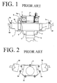
- Figs. 1 to 3 show a known structure for mounting a cable reel and turn indicator switches onto a steering shaft.
- a steering shaft 1 comprises an outer tube (tubular ring) 1a at the end where the steering wheel is fitted.
- An edge of the tubular ring 1a is bonded to three or four stays 2 by welding. These stays 2 are arranged at a given interval in the circumferential direction.
- the switch body 3 is then fixed onto the stays 2 by first bolts 4.
- the diametrically opposing sides of the switch body 3 are then provided with a corresponding lighting switch holder 3a or 3b, into which a turn indicator switch 5A or 5B is laterally inserted.
- the corresponding lighting switch holder 3a or 3b and turn indicator switch 5A or 5B are then clamped by second bolts 6.
- the upper side (as shown in Fig. 1) of the switch body 3 comprises three or four projecting cable reel holders 3c which are arranged at a given interval in the circumferential direction of the switch body 3.
- the cable reel 7 includes corresponding holder portions 8a extending horizontally from the base of its fixed element 8. Subsequently, the holder portions 8a are clamped onto the cable reel holders 3c by third bolts 9.
- a switch body 3 is first fixed on stays 2 projecting from a steering shaft 1 by means of first bolts.
- the turn indicator switches 5A and 5B are then fixed to the switch body 3 by second bolts, whilst a cable reel 7 is fixed to the switch body 3 by third bolts.
- bolt-fixing sites amount to about ten, and may downgrade the precision in their mutual positioning.
- Such a structure must employ a number of bolts, e.g. for fixing the switch body 3. It also calls for many fittings or fixtures, adding to material costs. Furthermore, the high number of bolts increases the number of screwing steps, further raising production costs.
- a main object of the invention is to provide a fitting structure in which the number of fittings and bolt-fixing sites is reduced, so that productivity of car parts assemblies is improved, and production costs are reduced.
- a structure for mounting a cable reel and a turn indicator switching means onto a steering shaft comprises three or four substantially L-shaped first stays extending from the steering shaft and arranged at a given interval in the circumferential direction of the shaft. The cable reel then engages the first stays.
- the structure further comprises two-level stays which form a space therebetween, whereby the turn indicator switching means is fitted into the space.
- the two-level stays comprise two second stays which are arranged respectively between two first stays and extend substantially perpendicularly from the steering shaft. They also comprise corresponding third stays which extend from the cable reel and are arranged in substantially parallel relation over the length of second stays, whereby the turn indicator switching means is fitted into a space between the second stays and the third stays.
- the two-level stays comprise two second stays arranged respectively between two first stays.
- Each of the second stays then comprises a first support which extends substantially perpendicularly from the steering shaft, and a second support which initially extends perpendicularly from the first support, then in parallel relation over the length of the first support, whereby the turn indicator switching means is fitted into a space between the first support and the second support.
- the turn indicator switches may respectively comprise a first face and a second face, the first face including a first protrusion with a first recess, whist the second face including a second protrusion with a second recess.
- the first recess thus engages with the second stays, whilst the second recess engages with the third stay.
- the turn indicator switching means and the steering shaft are then fixed by a fixing means.
- the turn indicator switching means comprises a first face and a second face, the first face including a first protrusion with a first recess, whist the second face including a second protrusion with a second recess.
- the first recess thus engages with the first support, whilst the second recess engages with the second support.
- the turn indicator switching means and the steering shaft are then fixed by a fixing means.
- the cable reel and the first stays are held by a holding means.
- the first stays comprise respectively a vertical portion extending in parallel relation over the length of the steering shaft, the vertical portion having an internal circular face and a substantially median section thereon.
- the holding means then comprises stoppers, which extend from the median section of the internal circular face towards the cable reel.
- the cable reel may include an external circular face
- the first stays may include an internal circular face.
- the holding means then comprises a pair of complementary locking means respectively provided on the external circular face of the cable reel and on the internal circular face of the first stays.
- the present invention obviates the need for a switch body which was considered as an essential part of the steering shaft structure.
- the cable reel and the turn indicator switching means are thus directly fitted onto the stays extending from the steering shaft.
- the first stays serve not only for fitting with the cable reel, but also for fixing the turn indicator.
- the third stays extend from the cable reel fitted with the first stays.
- the second stays extend from the steering shaft.
- the turn indicator switching means is then fitted between the third stays and the second stays.
- the cable reel is fixed not only with the steering shaft, but also with the turn indicator switching means, by virtue of the first stays. The position of the cable reel can thus be properly adjusted, so that the precision of its fixture position is improved.
- the turn indicator switching means is fixed not only with the steering shaft, but also with the cable reel, by virtue of the second stays. The position of the turn indicator switching means can thus be properly adjusted, so that the precision of its fixture position is improved.
- the turn indicator switching means and the steering shaft may be fixed by a fixing means.
- the fixing means is not necessarily required.
- the cable reel and the first stays are fixed without using bolts, and likewise for the turn indicator switching means and the second and third stays. Consequently, about ten bolting sites, otherwise thought necessary, are obviated. Accordingly, the mounting process is greatly simplified.
- the steering shaft structure is rendered lighter, and can be miniaturized.
- a pair of complementary locking means is provided on the external circular face of the cable reel and on the first stays, so that the cable reel and the first stays are fixed by locking. They are then fixed with a fixing means.
- the turn indicator switching means comprises a first face and a second face, the first face including a first protrusion with a first recess, and the second face including a second protrusion with a second recess. The first recess thus engages with the first support, whilst the second recess engages with the second support.
- the turn indicator switching means and the steering shaft are then fixed by a fixing means.
- the present embodiment requires no switch body, as in the first embodiment.
- the number of fittings or parts is thus reduced. Consequently, the structure is miniaturized, and assembling processes are simplified.
- Figs. 4 to 7 show a first embodiment of the present invention.
- An outer tube 10a is fixed to the steering wheel receiving side of the steering shaft 10.
- two second stays 12 (12A and 12B) are bonded by welding, respectively between two diametrically opposing first stays 11.
- the first stays 11 are substantially in the form of a letter L, respectively comprising a horizontal base portion 11a, and a vertical portion 11b projecting upwards from the horizontal base portion (Fig. 4A).
- the edge of the horizontal base portion 11a is fixed to the outer tube 10a.
- the horizontal cross-section of the respective vertical portions 11b forms a circular arc having a large curvature.
- a cable reel 20 has a cylindrical shape. It includes a fixed element 21 having an outer circular wall 21a with an external and internal circular face, and a base wall 21b (Figs. 4A and 5). When a cylindrical cable reel 20 is mounted onto the steering shaft 10, the respective vertical portions 11b of the stays 11 engage with the external face of the outer circular wall 21a of the fixed element 21.
- stoppers 11c may be provided at a radially inward side of the vertical portions 11b of the stays 11.
- the stoppers 11c project upwards from a substantially median section on the internal circular face of the vertical portions 11b.
- the stoppers 11c abuts against the base wall 21b of the fixed element 21 of cable reel 20 from its underside, and define the fitting position of the cable reel 20.
- the cable reel 20 comprises a mobile element 22 mounted to the steering wheel receiving side.
- the fixed element 21 comprises a base wall 21b having a flat ring shape, and an outer circular wall 21a.
- the mobile element 22 comprises an inner circular wall 22a, and a top wall 22b having a flat ring shape.
- the mobile element 22 is then assembled with the fixed element 21 in a freely rotatable way, thereby forming a torus shaped device 23.
- a flat electrical cable is stored in a helically wound state inside this toroidal device 23.
- the base wall 21b of the fixed element 21 is provided with a pair of opposing third stays 25 (25A and 25B) extending radially outwardly from the base wall 21b of the cable reel 20.
- first stays 11 may be extended along the outer circular wall 21a of the cable reel,20, and the top side of this outer circular wall 21a may be provided with locking means, e.g. U-shaped detents 21c, into which the extended first stays 11 are fitted.
- locking means e.g. U-shaped detents 21c
- the two second stays 12A and 12B are provided on the outer tube 10a of the steering shaft 10, and extend outwardly in a substantially radial direction thereof. Further, the third stays 25 are provided on the cable reel 20 fitted with the first stays 11, and extend with a parallel distance L1 over the second stays 12A and 12B.
- the distance L1 is sufficiently large enough to the interposition of the switch boxes 30a of the turn indicator switches 30 (30A and 30B).
- the turn indicator switches 30A and 30B of the invention are arranged at substantially opposing sides of the steering shaft, and include a switch box, respectively.
- the switch boxes 30a further comprise, respectively, a first (e.g. bottom) protrusion 32 with a first recess 32a at its first (e.g. bottom) side, and a second (e.g. top) protrusion 31 with a second- recess 31a at its second (e.g. top) side.
- the bottom and top protrusions 32 and 31 further include a first (bottom) hole 32b and a second (top) hole 31b, respectively.
- each of the third stays 25 and second stays 12 comprise a third-stay hole 25a and a second-stay hole 12a (equivalent to 25a of Fig. 4B, but not shown in the figures), respectively. Accordingly, when the third stays 25 are fitted with the second recesses 31a, snap bolts 34 can be clamped through the third-stay holes 25a and second hole 31b. Likewise, when the second stays 12 are fitted with the first recesses 32a, other snap bolts 34 can be clamped through the second-stay holes 12a (see supra) and first hole 32b.
- the cable reel 20 engages with the first stays 11 from the top side (of Fig. 4A) along the steering shaft 10.
Landscapes
- Engineering & Computer Science (AREA)
- Mechanical Engineering (AREA)
- Steering Controls (AREA)
- Switches With Compound Operations (AREA)
- Lighting Device Outwards From Vehicle And Optical Signal (AREA)
Abstract
Description
- The present invention relates to a structure for mounting a cable reel and turn indicator switches onto a steering shaft in automobiles. The structure of the invention allows, inter alia, to obviate the need for equipment hitherto considered essential. It therefore simplifies the construction of automobiles fittings and improves fitting process efficiency. In this technical field, the turn indicator switches are also known as winker- or blinker-lighting switches.
- Figs. 1 to 3 show a known structure for mounting a cable reel and turn indicator switches onto a steering shaft. Such a
steering shaft 1 comprises an outer tube (tubular ring) 1a at the end where the steering wheel is fitted. An edge of thetubular ring 1a is bonded to three or four stays 2 by welding. Thesestays 2 are arranged at a given interval in the circumferential direction. Theswitch body 3 is then fixed onto thestays 2 byfirst bolts 4. The diametrically opposing sides of theswitch body 3 are then provided with a correspondinglighting switch holder turn indicator switch lighting switch holder turn indicator switch second bolts 6. Further, the upper side (as shown in Fig. 1) of theswitch body 3 comprises three or four projectingcable reel holders 3c which are arranged at a given interval in the circumferential direction of theswitch body 3. Thecable reel 7 includescorresponding holder portions 8a extending horizontally from the base of itsfixed element 8. Subsequently, theholder portions 8a are clamped onto thecable reel holders 3c bythird bolts 9. - In the prior art techniques mentioned above, a
switch body 3 is first fixed on stays 2 projecting from asteering shaft 1 by means of first bolts. Theturn indicator switches switch body 3 by second bolts, whilst acable reel 7 is fixed to theswitch body 3 by third bolts. In such a construction, bolt-fixing sites amount to about ten, and may downgrade the precision in their mutual positioning. - Moreover, such a structure must employ a number of bolts, e.g. for fixing the
switch body 3. It also calls for many fittings or fixtures, adding to material costs. Furthermore, the high number of bolts increases the number of screwing steps, further raising production costs. - In view of the above, a main object of the invention is to provide a fitting structure in which the number of fittings and bolt-fixing sites is reduced, so that productivity of car parts assemblies is improved, and production costs are reduced.
- To this end, there is provided a structure for mounting a cable reel and a turn indicator switching means onto a steering shaft. The structure comprises three or four substantially L-shaped first stays extending from the steering shaft and arranged at a given interval in the circumferential direction of the shaft. The cable reel then engages the first stays. The structure further comprises two-level stays which form a space therebetween, whereby the turn indicator switching means is fitted into the space.
- Preferably, the two-level stays comprise two second stays which are arranged respectively between two first stays and extend substantially perpendicularly from the steering shaft. They also comprise corresponding third stays which extend from the cable reel and are arranged in substantially parallel relation over the length of second stays, whereby the turn indicator switching means is fitted into a space between the second stays and the third stays.
- Preferably yet, the two-level stays comprise two second stays arranged respectively between two first stays. Each of the second stays then comprises a first support which extends substantially perpendicularly from the steering shaft, and a second support which initially extends perpendicularly from the first support, then in parallel relation over the length of the first support, whereby the turn indicator switching means is fitted into a space between the first support and the second support.
- The turn indicator switches may respectively comprise a first face and a second face, the first face including a first protrusion with a first recess, whist the second face including a second protrusion with a second recess. The first recess thus engages with the second stays, whilst the second recess engages with the third stay. The turn indicator switching means and the steering shaft are then fixed by a fixing means.
- Likewise, the turn indicator switching means comprises a first face and a second face, the first face including a first protrusion with a first recess, whist the second face including a second protrusion with a second recess. The first recess thus engages with the first support, whilst the second recess engages with the second support. The turn indicator switching means and the steering shaft are then fixed by a fixing means.
- In a preferred embodiment, the cable reel and the first stays are held by a holding means.
- In such a case, the first stays comprise respectively a vertical portion extending in parallel relation over the length of the steering shaft, the vertical portion having an internal circular face and a substantially median section thereon. The holding means then comprises stoppers, which extend from the median section of the internal circular face towards the cable reel.
- Alternatively, the cable reel may include an external circular face, whereas the first stays may include an internal circular face. The holding means then comprises a pair of complementary locking means respectively provided on the external circular face of the cable reel and on the internal circular face of the first stays.
- As mentioned above, the present invention obviates the need for a switch body which was considered as an essential part of the steering shaft structure. The cable reel and the turn indicator switching means are thus directly fitted onto the stays extending from the steering shaft. In other words, the first stays serve not only for fitting with the cable reel, but also for fixing the turn indicator.
- The third stays extend from the cable reel fitted with the first stays. The second stays extend from the steering shaft. The turn indicator switching means is then fitted between the third stays and the second stays. In such a configuration, the cable reel is fixed not only with the steering shaft, but also with the turn indicator switching means, by virtue of the first stays. The position of the cable reel can thus be properly adjusted, so that the precision of its fixture position is improved. Likewise, the turn indicator switching means is fixed not only with the steering shaft, but also with the cable reel, by virtue of the second stays. The position of the turn indicator switching means can thus be properly adjusted, so that the precision of its fixture position is improved.
- As mentioned above, the turn indicator switching means and the steering shaft may be fixed by a fixing means. However, when the stays are press-fitted into the recesses, use of the fixing means is not necessarily required.
- Further, the cable reel and the first stays are fixed without using bolts, and likewise for the turn indicator switching means and the second and third stays. Consequently, about ten bolting sites, otherwise thought necessary, are obviated. Accordingly, the mounting process is greatly simplified.
- Furthermore, as there is no longer any need for a switch body, the steering shaft structure is rendered lighter, and can be miniaturized.
- In a variant second embodiment, a pair of complementary locking means is provided on the external circular face of the cable reel and on the first stays, so that the cable reel and the first stays are fixed by locking. They are then fixed with a fixing means. In this embodiment, the turn indicator switching means comprises a first face and a second face, the first face including a first protrusion with a first recess, and the second face including a second protrusion with a second recess. The first recess thus engages with the first support, whilst the second recess engages with the second support. The turn indicator switching means and the steering shaft are then fixed by a fixing means.
- The present embodiment requires no switch body, as in the first embodiment. The number of fittings or parts is thus reduced. Consequently, the structure is miniaturized, and assembling processes are simplified.
- The above and the other objects, features and advantages of the present invention will be made apparent from the following description of the preferred embodiments, given as non-limiting examples, with reference to the accompanying drawings, in which:
- Fig. 1 is a elevational side view of a prior art steering shaft structure, with hidden portions partially in phantom;
- Fig. 2 is an exploded view of a switch body and turn indicator switches, known in the prior art;
- Fig. 3 is a perspective view of a cable reel, and turn indicator switches attached to a switch body, both known in the prior art;
- Fig. 4A is a cross-sectional side view of a steering shaft structure according to a first embodiment of the invention, in which first stays are biased by 45° with regard to switch boxes;
- Fig. 4B is a cross-sectional view showing a partially enlarged portion of the steering shaft structure of Fig. 4A;
- Fig. 5 is a top plan view of a horizontal cross-section of a steering shaft equipped with a cable reel, according to the first embodiment of Fig. 4A;
- Fig. 6 is a cross-sectional side view showing how a turn indicator switches are mounted onto a steering shaft;
- Fig. 7A is a side elevational view of a steering shaft;
- Fig. 7B is the steering shaft of Fig. 7A, viewed from a different angle;
- Fig. 8 is a partial cross-sectional side view of a steering shaft according to a second embodiment of the present invention; and
- Fig. 9 is a cross-sectional side view of the steering shaft of Fig. 8.
-
- Embodiments of the present invention are described hereinafter with reference to the drawings.
- Figs. 4 to 7 show a first embodiment of the present invention. An
outer tube 10a is fixed to the steering wheel receiving side of the steeringshaft 10. Four first stays, for example, arranged at an interval of 90° in the circumferential direction of the steering shaft, are then bonded to an edge (upper side in Fig. 4) of theouter tube 10a by welding. Further, two second stays 12 (12A and 12B) are bonded by welding, respectively between two diametrically opposing first stays 11. - The first stays 11 are substantially in the form of a letter L, respectively comprising a
horizontal base portion 11a, and avertical portion 11b projecting upwards from the horizontal base portion (Fig. 4A). The edge of thehorizontal base portion 11a is fixed to theouter tube 10a. The horizontal cross-section of the respectivevertical portions 11b forms a circular arc having a large curvature. By comparison, acable reel 20 has a cylindrical shape. It includes a fixedelement 21 having an outercircular wall 21a with an external and internal circular face, and abase wall 21b (Figs. 4A and 5). When acylindrical cable reel 20 is mounted onto the steeringshaft 10, the respectivevertical portions 11b of thestays 11 engage with the external face of the outercircular wall 21a of the fixedelement 21. Further,stoppers 11c may be provided at a radially inward side of thevertical portions 11b of the stays 11. Thestoppers 11c project upwards from a substantially median section on the internal circular face of thevertical portions 11b. Thestoppers 11c abuts against thebase wall 21b of the fixedelement 21 ofcable reel 20 from its underside, and define the fitting position of thecable reel 20. - In addition to the fixed
element 21, thecable reel 20 comprises amobile element 22 mounted to the steering wheel receiving side. The fixedelement 21 comprises abase wall 21b having a flat ring shape, and an outercircular wall 21a. By contrast, themobile element 22 comprises an innercircular wall 22a, and atop wall 22b having a flat ring shape. Themobile element 22 is then assembled with the fixedelement 21 in a freely rotatable way, thereby forming a torus shapeddevice 23. A flat electrical cable is stored in a helically wound state inside thistoroidal device 23. - The
base wall 21b of the fixedelement 21 is provided with a pair of opposing third stays 25 (25A and 25B) extending radially outwardly from thebase wall 21b of thecable reel 20. - Likewise, the first stays 11 may be extended along the outer
circular wall 21a of the cable reel,20, and the top side of this outercircular wall 21a may be provided with locking means, e.g.U-shaped detents 21c, into which the extended first stays 11 are fitted. - The two
second stays outer tube 10a of the steeringshaft 10, and extend outwardly in a substantially radial direction thereof. Further, the third stays 25 are provided on thecable reel 20 fitted with the first stays 11, and extend with a parallel distance L1 over the second stays 12A and 12B. The distance L1 is sufficiently large enough to the interposition of theswitch boxes 30a of the turn indicator switches 30 (30A and 30B). - The turn indicator switches 30A and 30B of the invention are arranged at substantially opposing sides of the steering shaft, and include a switch box, respectively. The
switch boxes 30a further comprise, respectively, a first (e.g. bottom)protrusion 32 with afirst recess 32a at its first (e.g. bottom) side, and a second (e.g. top)protrusion 31 with a second-recess 31a at its second (e.g. top) side. The bottom andtop protrusions hole 32b and a second (top)hole 31b, respectively. Moreover, each of the third stays 25 and second stays 12 comprise a third-stay hole 25a and a second-stay hole 12a (equivalent to 25a of Fig. 4B, but not shown in the figures), respectively. Accordingly, when the third stays 25 are fitted with thesecond recesses 31a, snapbolts 34 can be clamped through the third-stay holes 25a andsecond hole 31b. Likewise, when the second stays 12 are fitted with thefirst recesses 32a,other snap bolts 34 can be clamped through the second-stay holes 12a (see supra) andfirst hole 32b. - In this configuration, the
cable reel 20 engages with the first stays 11 from the top side (of Fig. 4A) along the steeringshaft 10. When locking
Claims (8)
- A structure for mounting a cable reel (20) and a turn indicator switching means (30) onto a steering shaft (10), said structure comprising three or four substantially L-shaped first stays (11) extending from said steering shaft (10) and arranged at a given interval in the circumferential direction of said shaft (10), whereby said cable reel (20) engages with said first stays (11), said structure further comprising two-level stays which form a space therebetween, whereby said turn indicator switching means (30) is fitted into said space.
- The structure according to claim 1, wherein said two-level stays comprise two second stays (12) which are arranged respectively between two first stays (11) and extend substantially perpendicularly from said steering shaft (10), on the one hand, and corresponding third stays (25) which extend from said cable reel (20) and are arranged in substantially parallel relation over the length of said second stays (12) on the other, whereby said turn indicator switching means (30) is fitted into a space between said second stays (12) and said third stays (25).
- The structure according to claim 1, wherein said two-level stays comprise two second stays (12') arranged respectively between two first stays (11'), and each of said second stays (12') comprises a first support (12a') which extends substantially perpendicularly from said steering shaft (10), and a second support (12b') which initially extends perpendicularly from a part of said first support (12a'), then in parallel relation over the length of said first support (12a'), whereby said turn indicator switching means (30) is fitted into a space between said first support (12a') and said second support (12b').
- The structure according to claim 2, wherein said turn indicator switching means (30) comprises a first face and a second face, said first face including a first protrusion (32) with a first recess (32a), and said second face including a second protrusion (31) with a second recess (31a), wherein said first recess (32a) engages with said second stays (12), whilst said second recess (31a) engages with said third stay (25), and wherein said turn indicator switching means (30) and said steering shaft (10) are fixed by a fixing means (34).
- The structure according to claim 3, wherein said turn indicator switching means (30) comprises a first face and a second face, said first face including a first protrusion (32) with a first recess (32a), whist said second face including a second protrusion (31) with a second recess (31a), wherein said first recess engages with said first support (12a'), whilst said second recess (31a) engages with said second support (12b'), and wherein said turn indicator switching means (30) and said steering shaft (10) are fixed by a fixing means (34).
- The structure according to any one of claims 1 to 5, wherein said cable reel (20) and said first stays (11) are held by a holding means.
- The structure according to claim 6, wherein said first stays (11) comprise respectively a vertical portion (11b) extending in parallel relation over the length of said steering shaft (10), said vertical portion (11b) having an internal circular face and a substantially median section thereon, and wherein said holding means comprises stoppers (11c) which extend from said median section of said internal circular face towards said cable reel (20).
- The structure according to claim 6, wherein said cable reel (20') includes an external circular face (21a'), whereas said first stays (11') includes an internal circular face, and wherein said holding means comprises a pair of complementary locking means (11d', 21c') respectively provided on said external circular face (21a) of said cable reel (20) and on said internal circular face of said first stays (11).
Applications Claiming Priority (2)
| Application Number | Priority Date | Filing Date | Title |
|---|---|---|---|
| JP11170323A JP2001006493A (en) | 1999-06-16 | 1999-06-16 | Mounting structure of cable reel and blinker / lighting switch to steering shaft |
| JP17032399 | 1999-06-16 |
Publications (2)
| Publication Number | Publication Date |
|---|---|
| EP1060947A2 true EP1060947A2 (en) | 2000-12-20 |
| EP1060947A3 EP1060947A3 (en) | 2006-05-31 |
Family
ID=15902838
Family Applications (1)
| Application Number | Title | Priority Date | Filing Date |
|---|---|---|---|
| EP00401681A Withdrawn EP1060947A3 (en) | 1999-06-16 | 2000-06-14 | Structure for mounting a cable reel and turn indicator switches onto a steering shaft |
Country Status (3)
| Country | Link |
|---|---|
| US (1) | US6267610B1 (en) |
| EP (1) | EP1060947A3 (en) |
| JP (1) | JP2001006493A (en) |
Families Citing this family (6)
| Publication number | Priority date | Publication date | Assignee | Title |
|---|---|---|---|---|
| JP2001294104A (en) * | 2000-04-11 | 2001-10-23 | Sumitomo Wiring Syst Ltd | Integrated electrical components with cable reel and combination switch |
| JP2001294161A (en) * | 2000-04-14 | 2001-10-23 | Sumitomo Wiring Syst Ltd | Assembly of cable reel and combination switch |
| KR100387858B1 (en) * | 2000-12-29 | 2003-06-18 | 현대자동차주식회사 | multifunction switch installing for steering shaft |
| DE60325133D1 (en) * | 2002-04-20 | 2009-01-22 | Kia Motors Corp | Steering column mounted automatic transmission control unit with manual shift mode |
| DE10330481A1 (en) * | 2003-07-01 | 2005-01-20 | Valeo Schalter Und Sensoren Gmbh | Fastening device for fastening a steering column assembly module on a steering column jacket has a sleeve-type clamping element to fit between a steering column jacket and a fastening section |
| CN107128403B (en) * | 2017-04-28 | 2019-11-05 | 长乐净能新材料科技有限公司 | Stop safety guard around a kind of road |
Family Cites Families (5)
| Publication number | Priority date | Publication date | Assignee | Title |
|---|---|---|---|---|
| JPH0976826A (en) * | 1995-09-08 | 1997-03-25 | Niles Parts Co Ltd | Vehicle rotation connector screw fastening structure |
| JP3117632B2 (en) * | 1995-11-24 | 2000-12-18 | ナイルス部品株式会社 | Mounting structure of rotary connector and switch |
| JP3146157B2 (en) * | 1996-05-13 | 2001-03-12 | ナイルス部品株式会社 | Mounting structure of combination switch |
| JP3333387B2 (en) * | 1996-05-29 | 2002-10-15 | ナイルス部品株式会社 | Switch mounting structure |
| JPH1064647A (en) | 1996-08-26 | 1998-03-06 | Yazaki Corp | Connector with steering angle sensor and column structure using the same |
-
1999
- 1999-06-16 JP JP11170323A patent/JP2001006493A/en not_active Withdrawn
-
2000
- 2000-06-14 EP EP00401681A patent/EP1060947A3/en not_active Withdrawn
- 2000-06-15 US US09/594,032 patent/US6267610B1/en not_active Expired - Fee Related
Non-Patent Citations (1)
| Title |
|---|
| None |
Also Published As
| Publication number | Publication date |
|---|---|
| EP1060947A3 (en) | 2006-05-31 |
| US6267610B1 (en) | 2001-07-31 |
| JP2001006493A (en) | 2001-01-12 |
Similar Documents
| Publication | Publication Date | Title |
|---|---|---|
| US8556290B2 (en) | Vehicle occupant restraint system for a vehicle sealing element | |
| JP5334565B2 (en) | Mounting structure for automotive room lamps | |
| US20170243706A1 (en) | Push switch | |
| JP5372594B2 (en) | Tolerance absorption structure of wire harness | |
| JP2011231909A (en) | Clip | |
| US9627732B2 (en) | Connector for cavity filter | |
| JP5300130B2 (en) | Mounting structure for automotive room lamps | |
| US6267610B1 (en) | Structure for mounting a cable reel and turn indicator switches onto a steering shaft | |
| US7019212B1 (en) | Cover plate arrangement | |
| US7658535B2 (en) | Lamp having improved vibration damping | |
| JP2005112082A (en) | Fixing structure using a pair of screw parts and antenna device including the same | |
| US6259192B1 (en) | Electric lamp | |
| KR20190134390A (en) | Display device | |
| US20230047376A1 (en) | Improved electrical connection device | |
| CN220518102U (en) | Automobile cup stand and automobile | |
| CN211107270U (en) | Combination switch installation component and vehicle steering mechanism | |
| JP4931847B2 (en) | Mounting structure for transformer holder and pole transformer | |
| JP2007245928A (en) | Automobile steering wheel structure | |
| US12496987B2 (en) | Protector and wire harness | |
| KR19990000610U (en) | Car bulbs | |
| KR100488789B1 (en) | Cup holder for car | |
| JP4160624B1 (en) | Transformer holder | |
| CN213035890U (en) | Connecting support matched with pipe column for fixing | |
| JP2007231656A (en) | Window regulator holder | |
| JP2566195Y2 (en) | Portable light |
Legal Events
| Date | Code | Title | Description |
|---|---|---|---|
| PUAI | Public reference made under article 153(3) epc to a published international application that has entered the european phase |
Free format text: ORIGINAL CODE: 0009012 |
|
| 17P | Request for examination filed |
Effective date: 20000617 |
|
| AK | Designated contracting states |
Kind code of ref document: A2 Designated state(s): AT BE CH CY DE DK ES FI FR GB GR IE IT LI LU MC NL PT SE |
|
| AX | Request for extension of the european patent |
Free format text: AL;LT;LV;MK;RO;SI |
|
| PUAL | Search report despatched |
Free format text: ORIGINAL CODE: 0009013 |
|
| AK | Designated contracting states |
Kind code of ref document: A3 Designated state(s): AT BE CH CY DE DK ES FI FR GB GR IE IT LI LU MC NL PT SE |
|
| AX | Request for extension of the european patent |
Extension state: AL LT LV MK RO SI |
|
| AKX | Designation fees paid |
Designated state(s): DE FR GB IT |
|
| 17Q | First examination report despatched |
Effective date: 20070706 |
|
| STAA | Information on the status of an ep patent application or granted ep patent |
Free format text: STATUS: THE APPLICATION HAS BEEN WITHDRAWN |
|
| 18W | Application withdrawn |
Effective date: 20070822 |