EP1060899A1 - Ink ribbon - Google Patents
Ink ribbon Download PDFInfo
- Publication number
- EP1060899A1 EP1060899A1 EP00112595A EP00112595A EP1060899A1 EP 1060899 A1 EP1060899 A1 EP 1060899A1 EP 00112595 A EP00112595 A EP 00112595A EP 00112595 A EP00112595 A EP 00112595A EP 1060899 A1 EP1060899 A1 EP 1060899A1
- Authority
- EP
- European Patent Office
- Prior art keywords
- carbon black
- sensor marks
- ink ribbon
- sensor
- weight portions
- Prior art date
- Legal status (The legal status is an assumption and is not a legal conclusion. Google has not performed a legal analysis and makes no representation as to the accuracy of the status listed.)
- Granted
Links
Images


Classifications
-
- B—PERFORMING OPERATIONS; TRANSPORTING
- B41—PRINTING; LINING MACHINES; TYPEWRITERS; STAMPS
- B41J—TYPEWRITERS; SELECTIVE PRINTING MECHANISMS, i.e. MECHANISMS PRINTING OTHERWISE THAN FROM A FORME; CORRECTION OF TYPOGRAPHICAL ERRORS
- B41J31/00—Ink ribbons; Renovating or testing ink ribbons
-
- B—PERFORMING OPERATIONS; TRANSPORTING
- B41—PRINTING; LINING MACHINES; TYPEWRITERS; STAMPS
- B41J—TYPEWRITERS; SELECTIVE PRINTING MECHANISMS, i.e. MECHANISMS PRINTING OTHERWISE THAN FROM A FORME; CORRECTION OF TYPOGRAPHICAL ERRORS
- B41J31/00—Ink ribbons; Renovating or testing ink ribbons
- B41J31/05—Ink ribbons having coatings other than impression-material coatings
- B41J31/08—Ink ribbons having coatings other than impression-material coatings the coatings being superimposed on impression-transfer material
-
- B—PERFORMING OPERATIONS; TRANSPORTING
- B41—PRINTING; LINING MACHINES; TYPEWRITERS; STAMPS
- B41J—TYPEWRITERS; SELECTIVE PRINTING MECHANISMS, i.e. MECHANISMS PRINTING OTHERWISE THAN FROM A FORME; CORRECTION OF TYPOGRAPHICAL ERRORS
- B41J35/00—Other apparatus or arrangements associated with, or incorporated in, ink-ribbon mechanisms
- B41J35/16—Multicolour arrangements
- B41J35/18—Colour change effected automatically
Definitions
- This invention relates to an ink ribbon having sensor marks and adapted to be used for thermal transfer recording. More particularly, it relates to an ink ribbon having sensor marks that can reliably be read in use.
- Sublimation type thermal transfer recording methods for forming an image by laying an ink ribbon having ink layers containing sublimating or thermally diffusive dyes and printing paper having a dye receiving layer one on the other, heating the ink layers typically by means of a thermal head according to the image information applied to it and transferring the dyes of the ink layers to the dye receiving layer of the printing paper are known.
- Such sublimation type thermal transfer recording methods are attracting attention because they can form a full color image with continuously changing color tones particularly in the case of making a hard copy of an image from a video tape.
- the sublimation type thermal transfer recording method is used with a printer that is adapted to use an ink ribbon typically provided with sensor marks for placing the ink ribbon in position. Since the sensor marks and the ink layers show respective optical translucent density that are different from each other, the printer using the ink ribbon can detect a sensor mark by way of a change in the translucent density of the ink ribbon to place the latter in position. The sensor marks are required to be reliably read by the sensor of the printer.
- the sensor of the printer may be of the transmission type and or of the transmission/reflection type.
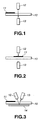
- the senor of the transmission type has a light emitting section 12 arranged to face the side of an ink ribbon 10 that carries sensor marks 11 and a light receiving section 13 arranged opposite to the light emitting section 12 so as to allow the ink ribbon 10 to pass therebetween.
- the light emitting section 12 of the transmission type sensor emits light, which is received by the light receiving section 13. As shown in FIG. 1, light emitted from the light emitting section 12 passes through the ink ribbon 10 in areas other than those of the sensor marks 11 and received by the light receiving section 13. However, the sensor marks 11 block light so that light emitted from the light emitting section 12 cannot pass therethrough. In this way, the transmission type sensor detects each sensor mark 11.
- a reflector panel 14 is arranged at the side of the ink ribbon 10 opposite to the side that carries sensor marks 11. Both a light emitting section 12 and a light receiving section 13 are arranged opposite to the reflector panel 14 so as to allow the ink ribbon 10 to pass therebetween. The light emitting section 12 and the light receiving section 13 are located at respective positions that are conjugative relative to each other.
- the light emitting section 12 of the transmission/reflection type sensor emit light, which is reflected by the reflector panel 14 and received by the light receiving section 13.
- light emitted from the light emitting section 12 passes through the ink ribbon 10 in areas other than those of the sensor marks 11 and reflected by the reflector panel 14 before it is received by the light receiving section 13.
- the sensor marks 11 block light so that light emitted from the light emitting section 12 cannot pass therethrough. In this way, the transmission/reflection type sensor detects each sensor mark 11.
- the reliability of detecting sensor marks 11 of the transmission type sensor can be improved by using thick sensor marks 11.
- the sensor marks 11 are too thick, they can be deformed while the ink ribbon 10 is stored for a long period of time as high pressure is applied to them by the parts of the ink ribbon 10 that are held in contact with them.
- the sensor marks 11 has a thickness same as that of the ink layers, which is normally about 2 ⁇ m or less. In other words, the sensor marks 11 have to meet both the requirement of a small thickness and that of a high translucent density.
- the light receiving section 13 can receive light reflected not by the reflector panel 14 but by the adjacent surface of a sensor mark 11 and mistake the sensor mark 11 for an area other than the sensor mark 11. Then, the sensor mark 11 is not correctly recognized to give rise to misalignment of the ink ribbon 10 and a failure on the part of the printer.
- an ink ribbon to be used for thermal transfer recording that shows an improved reliability for detecting sensor marks and can be stored without losing the improved reliability.
- an ink ribbon adapted to be used for a sublimation type thermal transfer printer said ink ribbon comprising:
- the sensor marks satisfy both the requirement of a high translucent density and that of a low surface reflectance to minimize detection errors.
- an ink ribbon adapted to be used for a sublimation type thermal transfer printer, said ink ribbon comprising:
- the sensor of the printer can reliably detect the sensor marks because the surface reflectance of the sensor marks is sufficiently low.
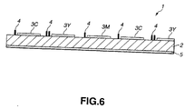
- FIGS. 6 and 7 are schematic illustrations of a first embodiment of ink ribbon according to the invention, showing its configuration.
- the ink ribbon 1 comprises a ribon-shaped substrate 2, a yellow ink layer 3Y, a magenta ink layer 3M, a cyan ink layer 3C, said yellow ink layer 3Y, said magenta ink layer 3M and said cyan ink layer 3C being formed on a surface of the substrate 2, sensor marks 4 formed on the same surface of the substrate 2 and arranged in the gaps separating said yellow ink layer 3Y, said magenta ink layer 3M and said cyan ink layer 3C and a back coat layer 5 formed on the other surface of the substrate 2.
- the substrate 2 may be made of a sheet of any known appropriate material that can be used for the substrate of an ink ribbon of the type under consideration. Specific examples of materials that can be used for the substrate 2 include polyester film, polystyrene film, polypropylene film, polysulfone film, polycarbonate film, polyimide film and aramid film.
- the substrate 2 has thickness preferably between 1 ⁇ m and 3 ⁇ m, more preferably between 2 ⁇ m and 10 ⁇ m.
- Each of the yellow ink layer 3Y, the magenta ink layer 3M and the cyan ink layer 3C contains a dye and a bonding agent.
- yellow dye that can be of the azo type, the dysazo type, the anthraquinone type, the styryl type or the pyridon-azo type may be used for the yellow ink layer 3Y.
- a specific example of yellow dye is "ESC-155" (trade name) available from Sumitomo Chemical Co., Ltd.
- magenta dye that can be of the azo type, the anthraquinone type, the styryl type or the heterocyclic type may be used for the magenta ink layer 3M.
- magenta dye is "ESC-451" (trade name) available from Sumitomo Chemical Co., Ltd.
- cyan dye that can be of the anthraquinone type, the naphthoquinone type, the heterocyclic azo type or the indoaniline type may be used for the cyan ink layer 3C.
- a specific example of cyan dye is "Foron Blue SR-PI" (trade name) available from Sandoz.
- the bonding agent may be made of any known resin material that is currently used as such for the ink layers of ink ribbons of the type under consideration.
- Specific materials that can be used for the boding agent of the ink layers of this embodiment include celllulose type resin materials such as methyl cellulose, ethyl cellulose, hydroxy cellulose, hydroxy-propyl-cellulose and cellulose acetate and vinyl type resin materials such as polyvinyl alcohol, polyvinyl butyral, polyvinyl acetoacetal, polyvinyl acetate and polystyrene along with urethane of various types.
- the sensor marks 4 contain first carbon black with an average particle diameter of 30 nm or less, second carbon black with an average particle diameter of 270 nm or more and a binder for dispersing said first carbon black and said second carbon black.
- average particle diameter refers to the value obtained by selecting 100 carbon black particles or more from a photographic image of the carbon black specimen taken through a transmission type electronic microscope (TEM) and calculating the average of the diameters of the selected particles.
- TEM transmission type electronic microscope
- the first carbon black having an average particle diameter of 30 nm or less raises the translucent density of the sensor marks 4, whereas the second carbon black having an average particle diameter of 270 nm or more gives an appropriate level of coarseness and hence a desired level of reflectance to the surface of the sensor marks 4.
- the sensor marks 4 contain the first carbon black having an average particle diameter of 30nm or less and the second carbon black having an average particle diameter of 270 nm or more, both the translucent density and the surface reflectance of the sensor marks 4 can be optimized.
- any known appropriate carbon black may be used for the first carbon black.
- Specific examples of carbon black that can be sued for the first carbon black of the sensor marks 4 include #850B, #980B, MCF88B and #44B (trade names) available from Mitsubishi Chemical Corp., BP-800, BP-L, REGAL-660 and REGAL-330 (trade names) available from CABOT, RAVEN-1255, RAVEN-1250, RAVEN-1020, RAVEN-780 and RAVEN-760 (trade names) available from Columbian Chemicals Company and Printex-55, Printex-45 and SB-550 (trade names) available from Degussa.
- the first carbon black has an average particle diameter of 25 nm or less. As the average particle diameter of the first carbon black is reduced, the particles become less visible and the translucent density of the sensor marks 4 rises. However, if the average particle diameter is too small, the carbon black particles become less dispersive and less stable in a dispersed state. Therefore, it is also preferable that the first carbon black has an average particle diameter of 15 nm or more.
- carbon black that can be used for the second carbon black of the sensor marks 4 include Sevacarb-MT (trade name) available from Columbian Chemicals Company and Thermax MT (trade name) available from Cancarb.
- the compounding ratio of the first carbon black to the second carbon black contained in the sensor marks 4 is between 70:30 and 30:70 by weight. If the ratio of the first carbon black is greater than 70 weight portions, that of the second carbon black is reduced accordingly to consequently worsen the surface reflectance of the sensor marks 4. On the other hand, if the ratio of the second carbon black is greater than 70 weight portions, that of the first carbon black is reduced accordingly to consequently worsen the translucent density of the sensor marks 4. In other words, the translucent density of the sensor marks 4 can be improved to reduce the reflectance thereof when the compounding ratio of the first carbon black to the second carbon black is found between 70:30 and 30:70 by weight.
- Materials that can be used for the binder for dispersing said first and second carbon blacks include vinyl chloride resin, polyurethane resin, phenoxy resin and polyester resin that may or may not be denatured as well as cellulose esters such as cellulose acetate butylate. Additionally, thermoplastic resins, thermosetting resins, reactive resins and resins that are set when irradiated with electron beams can also be used for the binder.
- the ratio of the binder to said first and second carbon blacks is preferably between 0.5 and 3.
- the first and second carbon blacks remain highly stable and operate effectively when the PB ratio is found within this range.
- the sensor marks 4 have a thickness between 0.5 ⁇ m and 1.5 ⁇ m.
- the sensor marks 4 do not provide a satisfactory translucent density if their thickness is less than 0.5 ⁇ m, whereas they can give rise to undulations on the surface if they have a thickness greater than 1.5 ⁇ m and the ink ribbon is stored for a prolonged period of time.
- a hardener may be added to the sensor marks 4 in order to improve their durability.
- Multi-functional isocyanate can be used as the hardener to be added to the sensor marks 4.
- TD tolylenediisocyanate
- Such a hardener is preferably added by 20 to 100 weight portions to 100 portions of the entire resin used for the sensor marks 4.
- an organic pigment, an inorganic pigment and/or a lubricant may be added to the sensor marks 4 whenever necessary.
- the back coat layer 5 contains resin.
- the back coat layer 5 formed on the other surface of the substrate 2 serves to make the ink ribbon 1 frictionally slide on the printing head on a stable basis.
- a lubricant and/or a hardener may also be added to the back coat layer 5.
- the lubricant added to the back coat layer 5 reduces the friction between the ink ribbon 1 and the printing head to improve the movement of the ink ribbon 1 on the printing head.
- Materials that can be used for the lubricant include calcium carbonate and phosphates.
- the hardener added to the back coat layer 5 improves the durability of the ink ribbon 1 when the latter is driven to move on the printing head. Polyisocyanate can preferably be used as the hardener.
- the sensor marks 4 have a 45° reflectance of 30% or less to light having a wavelength of 950 nm.
- Sensor marks 4 having a 45° reflectance of 30% or less to light having a wavelength of 950 nm shows a satisfactorily low surface reflectance and hence the sensor of the printer can reliably detect such sensor marks.
- an ink ribbon 1 having such sensor marks 4 can reduce detection errors and hence operates excellently.
- the 45° reflectance of 30% or less to light having a wavelength of 950nm of the sensor marks 4 can be realized by appropriately defining the particle diameter and the compounding ratio of the carbon blacks contained in the sensor marks 4. More specifically, such a reflectance can be realized for the sensor marks 4 by make the latter contain first carbon black with an average particle diameter of 30 nm or less and second carbon black with an average particle diameter of 270 nm or more.
- the present invention is described above by way of an embodiment, it should be noted that the present invention is by no means limited to the above embodiments, which may be altered or modified in various different ways without departing from the scope of the invention.
- the arrangement of the ink layers and the sensor marks may be varied depending on the type of the printer with which the ink ribbon is used.
- the sensor marks 4 are arranged to cross the entire width of the substrate 2 in the above embodiment of ink ribbon according to the invention, the sensor marks 4 do not necessarily have to cross the entire width of the substrate 2 as in the case of the embodiment illustrated in FIG. 8.
- a number of specimens of ink ribbon according to the invention were prepared and the performances thereof were evaluated in a manner as described below.
- the paints as listed below were prepared for the sensor marks, the back coat layer, the yellow ink layer, the magenta ink layer and the cyan ink layer of a specimen of ink ribbon according to the invention.
- the paint for the sensor marks was prepared by putting the materials as listed below together, mixing and crashing them in a ball mill for several minutes and causing the mixture to pass through a filter having a pore diameter of 5 ⁇ m.
- first carbon black 20 weight portions (RAVEN-1255 available from Columbian Chemicals Company : average particle diameter 23 ⁇ m)
- second carbon black 80 weight portions (Sevacarb MT available from Columbian Chemicals Company : average particle diameter 350 ⁇ m)
- polyester-polyurethane (containing SO 3 Na polar groups): 100 weight portions (UR-8300 available from Toyobo Co., Ltd.)
- the paint for the back coat layer was prepared by putting the materials as listed below together, mixing and stirring them in a dissolver for two hours and causing the mixture to pass through a filter having a pore diameter of 50 ⁇ m except the hardener that was added an hour prior to the application of the paint for the back coat layer.
- polyvinyl butyral 100 weight portions (S-LEC BX-55z available from Sekisui Chemical Co., Ltd.)
- polyisocyanate 50 weight portions (Coronate L-50E available from Nippon Polyurethane Co., Ltd.)
- the paint for the yellow ink layer was prepared by putting the materials as listed below together, mixing and stirring them in a dissolver for two hours and causing the mixture to pass through a filter having a pore diameter of 50 ⁇ m.
- polyvinyl butyral 100 weight portions (3000K available from Denki Kagaku Kogyo K. K.)
- the paint for the magenta ink layer was prepared by putting the materials as listed below together, mixing and stirring them in a dissolver for two hours and causing the mixture to pass through a filter having a pore diameter of 50 ⁇ m.
- magenta dye 100 weight portions (ESC-451 available from Sumitomo Chemical Co., Ltd.)
- polyvinyl butyral 100 weight portions (3000K available from Denki Kagaku Kogyo K. K.)
- the paint for the cyan ink layer was prepared by putting the materials as listed below together, mixing and stirring them in a dissolver for two hours and causing the mixture to pass through a filter having a pore diameter of 50 ⁇ m.
- cyan dye 100 weight portions (Foron Blue SR-PI available from Sandoz)
- polyvinyl butyral 100 weight portions (3000K available from Denki Kagaku Kogyo K. K.)
- the paint for the back coat layer prepared in a manner as described above was applied to one of the surfaces of a 6 ⁇ m thick polyester film (LUMILER available from Toray Industries, Inc.) to a thickness of 1 ⁇ m when dried and made to set at 60°C for 48 hours to produce the back coat layer.
- LUMILER available from Toray Industries, Inc.
- the paint for the sensor marks, the paint for the yellow ink layer, the paint for the magenta ink layer and the paint for the cyan ink layer were applied to the other surface of the ribbon-shaped substrate to a thickness of 1.5 ⁇ m for the sensor marks when dried and to a thickness of 1.0 ⁇ m for all the ink layers when dried to produce a ink ribbon carrying sensor marks, a yellow ink layer, a magenta ink layer and a cyan ink layer on that surface.
- a specimen of ink ribbon according to the invention was prepared as in Example 1 except that 30 weight portions of the first carbon black and 70 weight portions of the second carbon black were used for preparing the paint for the sensor marks.
- a specimen of ink ribbon according to the invention was prepared as in Example 1 except that 50 weight portions of the first carbon black and also 50 weight portions of the second carbon black were used for preparing the paint for the sensor marks.
- a specimen of ink ribbon according to the invention was prepared as in Example 1 except that 70 weight portions of the first carbon black and 30 weight portions of the second carbon black were used for preparing the paint for the sensor marks.
- a specimen of ink ribbon according to the invention was prepared as in Example 1 except that 80 weight portions of the first carbon black and 20 weight portions of the second carbon black were used for preparing the paint for the sensor marks.
- a specimen of ink ribbon according to the invention was prepared as in Example 1 except that RAVEN-760 (average particle diameter 30 nm) available from Columbian Chemicals Company was used for the first carbon black.
- a specimen of ink ribbon according to the invention was prepared as in Example 1 except that #850B (average particle diameter 18 nm) available from Mitsubishi Plastics, Inc. was used for the first carbon black.
- a specimen of ink ribbon according to the invention was prepared as in Example 1 except that 50 weight portions of the first carbon black and 50 weight portions of the second carbon black were used for preparing the paint for the sensor marks and the second carbon black was Thermax-MT (average particle diameter 270 nm) available from Cancarb.
- a specimen of ink ribbon was prepared as in Example 1 except that 70 weight portions of the first carbon black and 30 weight portions of the second carbon black were used for preparing the paint for the sensor marks and the second carbon black was #35 (average particle diameter 82 nm) available from Asahi Carbon.
- a specimen of ink ribbon was prepared as in Example 2 except that Regal 99R (average particle diameter 35 nm) available from CABOT was used for the first carbon black.
- the prepared specimens were then evaluated for the translucent density, the surface reflectance and the detection accuracy.
- P-300 Printer a printer having a reflection type sensor that is available from Olympus Optical Co., Ltd. was used with printing paper supplied by Sony Corp. for VPM-P50STB.
- the translucent density was evaluated by means of a Macbeth densitometer. Specimens with a translucent density of 1.5 or more were rated as good.
- the surface reflectance was evaluated by means of VG-ID, a reflectometer available from Nihon Denshoku Co., Ltd. More specifically, the 20° Gloss of the surface was observed and specimens with a value of 50 or less were rated as good.
- Table 1 below shows the results of the evaluation for the specimens of Examples 1 through 8 and Comparative Examples 1 and 2 along with the carbon black compositions of the sensor marks.
- an ink ribbon according to the invention and provided with sensor marks containing first carbon black with an average particle diameter of 30 nm or less and second carbon black with an average particle diameter of 270 nm or more can satisfy both the requirement of a high translucent density and that of a low surface reflectance to minimize detection errors and is free from the problem of undetected sensor marks when used with a printer having a sensor.
- the paints as listed below were prepared for the sensor marks, the back coat layer, the yellow ink layer, the magenta ink layer and the cyan ink layer of a specimen of ink ribbon according to the invention.
- the paint for the sensor marks was prepared by putting the materials as listed below together, mixing and crashing them in a ball mill for several minutes and causing the mixture to pass through a filter having a pore diameter of 5 ⁇ m.
- first carbon black 20 weight portions (RAVEN-1255 available from Columbian Chemicals Company : average particle diameter 23 ⁇ m)
- second carbon black 80 weight portions (Sevacarb MT available from Columbian Chemicals Company : average particle diameter 350 ⁇ m)
- polyester-polyurethane (containing SO 3 Na polar groups): 100 weight portions (UR-8300 available from Toyobo Co., Ltd.)
- the paint for the back coat layer was prepared by putting the materials as listed below together, mixing and stirring them in a dissolver for two hours and causing the mixture to pass through a filter having a pore diameter of 50 ⁇ m except the hardener that was added an hour prior to the application of the paint for the back coat layer.
- polyvinyl butyral 100 weight portions (S-LEC BX-55z available from Sekisui Chemical Co., Ltd.)
- polyisocyanate 50 weight portions (Coronate L-50E available from Nippon Polyurethane Co., Ltd.)
- the paint for the yellow ink layer was prepared by putting the materials as listed below together, mixing and stirring them in a dissolver for two hours and causing the mixture to pass through a filter having a pore diameter of 50 ⁇ m.
- polyvinyl butyral 100 weight portions (3000K available from Denki Kagaku Kogyo K. K.)
- the paint for the magenta ink layer was prepared by putting the materials as listed below together, mixing and stirring them in a dissolver for two hours and causing the mixture to pass through a filter having a pore diameter of 50 ⁇ m.
- magenta dye 50 weight portions (ESC-451 available from Sumitomo Chemical Co., Ltd.)
- polyvinyl butyral 50 weight portions (3000K available from Denki Kagaku Kogyo K. K.)
- the paint for the cyan ink layer was prepared by putting the materials as listed below together, mixing and stirring them in a dissolver for two hours and causing the mixture to pass through a filter having a pore diameter of 50 ⁇ m.
- cyan dye 100 weight portions (Foron Blue SR-PI available from Sandoz)
- polyvinyl butyral 100 weight portions (3000K available from Denki Kagaku Kogyo K. K.)
- the paint for the back coat layer prepared in a manner as described above was applied to one of the surfaces of a 6 ⁇ m thick polyester film (LUMILER available from Toray Industries, Inc.) to a thickness of 1 ⁇ m when dried and made to set at 60°C for 48 hours to produce the back coat layer.
- LUMILER available from Toray Industries, Inc.
- the paint for the sensor marks, the paint for the yellow ink layer, the paint for the magenta ink layer and the paint for the cyan ink layer were applied to the other surface of the ribbon-shaped substrate to a thickness of 1.5 ⁇ m for the sensor marks when dried and to a thickness of 1.0 ⁇ m for all the ink layers when dried to produce a ink ribbon carrying sensor marks, a yellow ink layer, a magenta ink layer and a cyan ink layer on that surface.
- a specimen of ink ribbon according to the invention was prepared as in Example 9 except that 50 weight portions of the first carbon black and also 50 weight portions of the second carbon black were used for preparing the paint for the sensor marks.
- a specimen of ink ribbon according to the invention was prepared as in Example 9 except that 60 weight portions of the first carbon black and 40 weight portions of the second carbon black were used for preparing the paint for the sensor marks.
- a specimen of ink ribbon according to the invention was prepared as in Example 9 except that 70 weight portions of the first carbon black and 30 weight portions of the second carbon black were used for preparing the paint for the sensor marks.
- the prepared specimens were then evaluated for the 45° reflectance to light with a wavelength of 950 nm and the detection accuracy.
- P-300 Printer a printer having a reflection type sensor that is available from Olympus Optical Co., Ltd, was used with printing paper supplied by Sony Corp. for VPM-P50STB.
- the 45° reflectance to light with a wavelength of 950 nm was evaluated by means of spectro-photometer MCPD-2000 available from Otsuka Denshi Co., Ltd.
- the 45° reflectance to light with a wavelength of 950 nm of a standard white panel as defined in JIS-P-8148 was rated as 100% and the corresponding reflectance of the sensor marks of each of the specimens was evaluated.
- the detection accuracy As for the detection accuracy, a printing operation was conducted continuously on a hundred sheets by means of the P-300 Printer of Olympus Optical Co., Ltd and the number of sensor marks that the sensor of the printer failed to detect at the cost of ink ribbon was counted. Specimens with no undetected sensor marks were rated as good. When evaluating the detection accuracy, the optical sensor of the printer was so adjusted that it was apt to fail to detect sensor marks.
- Table 2 below shows the results of the evaluation for the specimens of Examples 9 and 10 and Comparative Examples 3 and 4 along with the carbon black compositions of the sensor marks.
Abstract
Description
- This invention relates to an ink ribbon having sensor marks and adapted to be used for thermal transfer recording. More particularly, it relates to an ink ribbon having sensor marks that can reliably be read in use.
- Sublimation type thermal transfer recording methods for forming an image by laying an ink ribbon having ink layers containing sublimating or thermally diffusive dyes and printing paper having a dye receiving layer one on the other, heating the ink layers typically by means of a thermal head according to the image information applied to it and transferring the dyes of the ink layers to the dye receiving layer of the printing paper are known. Such sublimation type thermal transfer recording methods are attracting attention because they can form a full color image with continuously changing color tones particularly in the case of making a hard copy of an image from a video tape.
- The sublimation type thermal transfer recording method is used with a printer that is adapted to use an ink ribbon typically provided with sensor marks for placing the ink ribbon in position. Since the sensor marks and the ink layers show respective optical translucent density that are different from each other, the printer using the ink ribbon can detect a sensor mark by way of a change in the translucent density of the ink ribbon to place the latter in position. The sensor marks are required to be reliably read by the sensor of the printer.
- The sensor of the printer may be of the transmission type and or of the transmission/reflection type.
- Referring to FIGS. 1 and 2 of the accompanying drawings, the sensor of the transmission type has a
light emitting section 12 arranged to face the side of anink ribbon 10 that carriessensor marks 11 and alight receiving section 13 arranged opposite to thelight emitting section 12 so as to allow theink ribbon 10 to pass therebetween. - The
light emitting section 12 of the transmission type sensor emits light, which is received by thelight receiving section 13. As shown in FIG. 1, light emitted from thelight emitting section 12 passes through theink ribbon 10 in areas other than those of thesensor marks 11 and received by thelight receiving section 13. However, the sensor marks 11 block light so that light emitted from thelight emitting section 12 cannot pass therethrough. In this way, the transmission type sensor detects eachsensor mark 11. - In the case of the transmission/reflection type sensor as shown in FIGS. 3 and 4, a
reflector panel 14 is arranged at the side of theink ribbon 10 opposite to the side that carriessensor marks 11. Both alight emitting section 12 and alight receiving section 13 are arranged opposite to thereflector panel 14 so as to allow theink ribbon 10 to pass therebetween. Thelight emitting section 12 and thelight receiving section 13 are located at respective positions that are conjugative relative to each other. - Thus, the
light emitting section 12 of the transmission/reflection type sensor emit light, which is reflected by thereflector panel 14 and received by thelight receiving section 13. As shown in FIG. 3, light emitted from thelight emitting section 12 passes through theink ribbon 10 in areas other than those of thesensor marks 11 and reflected by thereflector panel 14 before it is received by thelight receiving section 13. However, the sensor marks 11 block light so that light emitted from thelight emitting section 12 cannot pass therethrough. In this way, the transmission/reflection type sensor detects eachsensor mark 11. - The reliability of detecting
sensor marks 11 of the transmission type sensor can be improved by usingthick sensor marks 11. - However, if the
sensor marks 11 are too thick, they can be deformed while theink ribbon 10 is stored for a long period of time as high pressure is applied to them by the parts of theink ribbon 10 that are held in contact with them. - In view of this problem, it is desirably that the
sensor marks 11 has a thickness same as that of the ink layers, which is normally about 2 µm or less. In other words, thesensor marks 11 have to meet both the requirement of a small thickness and that of a high translucent density. - Additionally, in the case of the transmission/reflection type sensor, if the sensor marks 11 show a high surface reflectance, the
light receiving section 13 can receive light reflected not by thereflector panel 14 but by the adjacent surface of asensor mark 11 and mistake thesensor mark 11 for an area other than thesensor mark 11. Then, thesensor mark 11 is not correctly recognized to give rise to misalignment of theink ribbon 10 and a failure on the part of the printer. - Efforts have been paid to optimize the chemical composition and the thickness of
sensor marks 11 in order to optimize the translucent density and the surface reflectance ofsensor marks 11. However, the problem of missing sensor marks of the sensor has not been completely eliminated to date. - In view of the above described circumstances, it is therefore the object of the present invention to provide an ink ribbon to be used for thermal transfer recording that shows an improved reliability for detecting sensor marks and can be stored without losing the improved reliability.
- According to the invention, the above object is achieved by providing an ink ribbon adapted to be used for a sublimation type thermal transfer printer, said ink ribbon comprising:
- a ribbon-shaped substrate;
- ink layers formed on a surface of said substrate and containing dyes;
- sensor marks formed on said surface of said substrate; and
- a back coat layer formed on the other surface of said substrate;
- said sensor marks containing first carbon black with an average particle diameter of 30 nm or less and second carbon black with an average particle diameter of 270 nm or more.
-
- With an ink ribbon according to the invention as described above, the sensor marks satisfy both the requirement of a high translucent density and that of a low surface reflectance to minimize detection errors.
- In another aspect of the invention, there is also provided an ink ribbon adapted to be used for a sublimation type thermal transfer printer, said ink ribbon comprising:
- a ribbon-shaped substrate;
- ink layers formed on a surface of said substrate and containing dyes; and
- sensor marks formed on said surface of said substrate carrying said ink layers;
- said sensor marks having a 45° reflectance of 30% or less to light with a wavelength of 950 nm.
-
- With an ink ribbon according to the invention, the sensor of the printer can reliably detect the sensor marks because the surface reflectance of the sensor marks is sufficiently low.
-
- FIG. 1 is a schematic illustration of a transmission type sensor detecting a sensor mark.
- FIG. 2 is another schematic illustration of a transmission type sensor detecting a sensor mark.
- FIG. 3 is a schematic illustration of a transmission/reflection type sensor detecting a sensor mark.
- FIG. 4 is another schematic illustration of a transmission/reflection type sensor detecting a sensor mark.
- FIG. 5 is another schematic illustration of a transmission/reflection type sensor detection a sensor, where light is reflected by the surface of the sensor mark.
- FIG. 6 is a schematic cross sectional view of an embodiment of ink ribbon according to the invention.
- FIG. 7 is a schematic plan view of the embodiment of ink ribbon of FIG. 6.
- FIG. 8 is a schematic plan view of another embodiment of ink ribbon according to the invention.
-
- Now, the present invention will be described in greater detail by referring to the accompanying drawings that illustrate preferred embodiments of the invention.
- FIGS. 6 and 7 are schematic illustrations of a first embodiment of ink ribbon according to the invention, showing its configuration.
- The
ink ribbon 1 comprises a ribon-shaped substrate 2, ayellow ink layer 3Y, amagenta ink layer 3M, acyan ink layer 3C, saidyellow ink layer 3Y, saidmagenta ink layer 3M and saidcyan ink layer 3C being formed on a surface of thesubstrate 2,sensor marks 4 formed on the same surface of thesubstrate 2 and arranged in the gaps separating saidyellow ink layer 3Y, saidmagenta ink layer 3M and saidcyan ink layer 3C and aback coat layer 5 formed on the other surface of thesubstrate 2. - The
substrate 2 may be made of a sheet of any known appropriate material that can be used for the substrate of an ink ribbon of the type under consideration. Specific examples of materials that can be used for thesubstrate 2 include polyester film, polystyrene film, polypropylene film, polysulfone film, polycarbonate film, polyimide film and aramid film. Thesubstrate 2 has thickness preferably between 1 µm and 3 µm, more preferably between 2 µm and 10 µm. - Each of the
yellow ink layer 3Y, themagenta ink layer 3M and thecyan ink layer 3C contains a dye and a bonding agent. - Any known yellow dye that can be of the azo type, the dysazo type, the anthraquinone type, the styryl type or the pyridon-azo type may be used for the
yellow ink layer 3Y. A specific example of yellow dye is "ESC-155" (trade name) available from Sumitomo Chemical Co., Ltd. - Any known magenta dye that can be of the azo type, the anthraquinone type, the styryl type or the heterocyclic type may be used for the
magenta ink layer 3M. A specific example of magenta dye is "ESC-451" (trade name) available from Sumitomo Chemical Co., Ltd. - Any known cyan dye that can be of the anthraquinone type, the naphthoquinone type, the heterocyclic azo type or the indoaniline type may be used for the
cyan ink layer 3C. A specific example of cyan dye is "Foron Blue SR-PI" (trade name) available from Sandoz. - The bonding agent may be made of any known resin material that is currently used as such for the ink layers of ink ribbons of the type under consideration. Specific materials that can be used for the boding agent of the ink layers of this embodiment include celllulose type resin materials such as methyl cellulose, ethyl cellulose, hydroxy cellulose, hydroxy-propyl-cellulose and cellulose acetate and vinyl type resin materials such as polyvinyl alcohol, polyvinyl butyral, polyvinyl acetoacetal, polyvinyl acetate and polystyrene along with urethane of various types.
- The sensor marks 4 contain first carbon black with an average particle diameter of 30 nm or less, second carbon black with an average particle diameter of 270 nm or more and a binder for dispersing said first carbon black and said second carbon black.
- The term "average particle diameter" as used herein refers to the value obtained by selecting 100 carbon black particles or more from a photographic image of the carbon black specimen taken through a transmission type electronic microscope (TEM) and calculating the average of the diameters of the selected particles.
- The first carbon black having an average particle diameter of 30 nm or less raises the translucent density of the sensor marks 4, whereas the second carbon black having an average particle diameter of 270 nm or more gives an appropriate level of coarseness and hence a desired level of reflectance to the surface of the sensor marks 4. In other words, by making the sensor marks 4 contain the first carbon black having an average particle diameter of 30nm or less and the second carbon black having an average particle diameter of 270 nm or more, both the translucent density and the surface reflectance of the sensor marks 4 can be optimized.
- Any known appropriate carbon black may be used for the first carbon black. Specific examples of carbon black that can be sued for the first carbon black of the sensor marks 4 include #850B, #980B, MCF88B and #44B (trade names) available from Mitsubishi Chemical Corp., BP-800, BP-L, REGAL-660 and REGAL-330 (trade names) available from CABOT, RAVEN-1255, RAVEN-1250, RAVEN-1020, RAVEN-780 and RAVEN-760 (trade names) available from Columbian Chemicals Company and Printex-55, Printex-45 and SB-550 (trade names) available from Degussa.
- Preferably, the first carbon black has an average particle diameter of 25 nm or less. As the average particle diameter of the first carbon black is reduced, the particles become less visible and the translucent density of the sensor marks 4 rises. However, if the average particle diameter is too small, the carbon black particles become less dispersive and less stable in a dispersed state. Therefore, it is also preferable that the first carbon black has an average particle diameter of 15 nm or more.
- Specific examples of carbon black that can be used for the second carbon black of the sensor marks 4 include Sevacarb-MT (trade name) available from Columbian Chemicals Company and Thermax MT (trade name) available from Cancarb.
- The compounding ratio of the first carbon black to the second carbon black contained in the sensor marks 4 is between 70:30 and 30:70 by weight. If the ratio of the first carbon black is greater than 70 weight portions, that of the second carbon black is reduced accordingly to consequently worsen the surface reflectance of the sensor marks 4. On the other hand, if the ratio of the second carbon black is greater than 70 weight portions, that of the first carbon black is reduced accordingly to consequently worsen the translucent density of the sensor marks 4. In other words, the translucent density of the sensor marks 4 can be improved to reduce the reflectance thereof when the compounding ratio of the first carbon black to the second carbon black is found between 70:30 and 30:70 by weight.
- Materials that can be used for the binder for dispersing said first and second carbon blacks include vinyl chloride resin, polyurethane resin, phenoxy resin and polyester resin that may or may not be denatured as well as cellulose esters such as cellulose acetate butylate. Additionally, thermoplastic resins, thermosetting resins, reactive resins and resins that are set when irradiated with electron beams can also be used for the binder.
- In the sensor marks 4, the ratio of the binder to said first and second carbon blacks (PB ratio) is preferably between 0.5 and 3. The first and second carbon blacks remain highly stable and operate effectively when the PB ratio is found within this range.
- Preferably, the sensor marks 4 have a thickness between 0.5 µm and 1.5 µm. The sensor marks 4 do not provide a satisfactory translucent density if their thickness is less than 0.5 µm, whereas they can give rise to undulations on the surface if they have a thickness greater than 1.5 µm and the ink ribbon is stored for a prolonged period of time.
- If necessary, a hardener may be added to the sensor marks 4 in order to improve their durability. Multi-functional isocyanate can be used as the hardener to be added to the sensor marks 4. Particularly, the use of tolylenediisocyanate (TD) is preferable. Such a hardener is preferably added by 20 to 100 weight portions to 100 portions of the entire resin used for the sensor marks 4. Besides the hardener, an organic pigment, an inorganic pigment and/or a lubricant may be added to the sensor marks 4 whenever necessary.
- The
back coat layer 5 contains resin. Theback coat layer 5 formed on the other surface of thesubstrate 2 serves to make theink ribbon 1 frictionally slide on the printing head on a stable basis. - A lubricant and/or a hardener may also be added to the
back coat layer 5. The lubricant added to theback coat layer 5 reduces the friction between theink ribbon 1 and the printing head to improve the movement of theink ribbon 1 on the printing head. Materials that can be used for the lubricant include calcium carbonate and phosphates. The hardener added to theback coat layer 5 improves the durability of theink ribbon 1 when the latter is driven to move on the printing head. Polyisocyanate can preferably be used as the hardener. - In another embodiment of
ink ribbon 1 according to the invention, the sensor marks 4 have a 45° reflectance of 30% or less to light having a wavelength of 950 nm. Sensor marks 4 having a 45° reflectance of 30% or less to light having a wavelength of 950 nm shows a satisfactorily low surface reflectance and hence the sensor of the printer can reliably detect such sensor marks. In other words, anink ribbon 1 havingsuch sensor marks 4 can reduce detection errors and hence operates excellently. - The 45° reflectance of 30% or less to light having a wavelength of 950nm of the sensor marks 4 can be realized by appropriately defining the particle diameter and the compounding ratio of the carbon blacks contained in the sensor marks 4. More specifically, such a reflectance can be realized for the sensor marks 4 by make the latter contain first carbon black with an average particle diameter of 30 nm or less and second carbon black with an average particle diameter of 270 nm or more.
- While the present invention is described above by way of an embodiment, it should be noted that the present invention is by no means limited to the above embodiments, which may be altered or modified in various different ways without departing from the scope of the invention. For instance, the arrangement of the ink layers and the sensor marks may be varied depending on the type of the printer with which the ink ribbon is used. While the sensor marks 4 are arranged to cross the entire width of the
substrate 2 in the above embodiment of ink ribbon according to the invention, the sensor marks 4 do not necessarily have to cross the entire width of thesubstrate 2 as in the case of the embodiment illustrated in FIG. 8. - A number of specimens of ink ribbon according to the invention were prepared and the performances thereof were evaluated in a manner as described below.
- The paints as listed below were prepared for the sensor marks, the back coat layer, the yellow ink layer, the magenta ink layer and the cyan ink layer of a specimen of ink ribbon according to the invention.
- The paint for the sensor marks was prepared by putting the materials as listed below together, mixing and crashing them in a ball mill for several minutes and causing the mixture to pass through a filter having a pore diameter of 5 µm.
-
first carbon black: 20 weight portions (RAVEN-1255 available from Columbian Chemicals Company : average particle diameter 23 µm) second carbon black: 80 weight portions (Sevacarb MT available from Columbian Chemicals Company : average particle diameter 350 µm) -
polyester-polyurethane (containing SO3Na polar groups): 100 weight portions (UR-8300 available from Toyobo Co., Ltd.) -
methyl ethyl ketone: 500 weight portions toluene: 500 weight portions - The paint for the back coat layer was prepared by putting the materials as listed below together, mixing and stirring them in a dissolver for two hours and causing the mixture to pass through a filter having a pore diameter of 50 µm except the hardener that was added an hour prior to the application of the paint for the back coat layer.
-
polyvinyl butyral: 100 weight portions (S-LEC BX-55z available from Sekisui Chemical Co., Ltd.) -
calcium carbonate: 10 weight portions (Hakuenka DD available from Shiraishi Kogyo Co., Ltd.) phosphate: 10 weight portions (Phosphanol RD-720 available from Toho Chemical Industry Co., Ltd.) phosphate: 20 weight portions (Prisurf A208S available from Dai-ichi Kogyo Seiyaku Co., Ltd.) -
methyl ethyl ketone: 800 weight portions toluene: 800 weight portions -
polyisocyanate: 50 weight portions (Coronate L-50E available from Nippon Polyurethane Co., Ltd.) - The paint for the yellow ink layer was prepared by putting the materials as listed below together, mixing and stirring them in a dissolver for two hours and causing the mixture to pass through a filter having a pore diameter of 50 µm.
-
yellow dye: 100 weight portions (ESC-155 available from Sumitomo Chemical Co., Ltd.) -
polyvinyl butyral: 100 weight portions (3000K available from Denki Kagaku Kogyo K. K.) -
methyl ethyl ketone: 900 weight portions toluene: 900 weight portions - The paint for the magenta ink layer was prepared by putting the materials as listed below together, mixing and stirring them in a dissolver for two hours and causing the mixture to pass through a filter having a pore diameter of 50 µm.
-
magenta dye: 100 weight portions (ESC-451 available from Sumitomo Chemical Co., Ltd.) -
polyvinyl butyral: 100 weight portions (3000K available from Denki Kagaku Kogyo K. K.) -
methyl ethyl ketone: 900 weight portions toluene: 900 weight portions - The paint for the cyan ink layer was prepared by putting the materials as listed below together, mixing and stirring them in a dissolver for two hours and causing the mixture to pass through a filter having a pore diameter of 50 µm.
-
cyan dye: 100 weight portions (Foron Blue SR-PI available from Sandoz) -
polyvinyl butyral: 100 weight portions (3000K available from Denki Kagaku Kogyo K. K.) -
methyl ethyl ketone: 900 weight portions toluene: 900 weight portions - Then, the paint for the back coat layer prepared in a manner as described above was applied to one of the surfaces of a 6 µm thick polyester film (LUMILER available from Toray Industries, Inc.) to a thickness of 1 µm when dried and made to set at 60°C for 48 hours to produce the back coat layer.
- Subsequently, the paint for the sensor marks, the paint for the yellow ink layer, the paint for the magenta ink layer and the paint for the cyan ink layer were applied to the other surface of the ribbon-shaped substrate to a thickness of 1.5 µm for the sensor marks when dried and to a thickness of 1.0 µm for all the ink layers when dried to produce a ink ribbon carrying sensor marks, a yellow ink layer, a magenta ink layer and a cyan ink layer on that surface.
- A specimen of ink ribbon according to the invention was prepared as in Example 1 except that 30 weight portions of the first carbon black and 70 weight portions of the second carbon black were used for preparing the paint for the sensor marks.
- A specimen of ink ribbon according to the invention was prepared as in Example 1 except that 50 weight portions of the first carbon black and also 50 weight portions of the second carbon black were used for preparing the paint for the sensor marks.
- A specimen of ink ribbon according to the invention was prepared as in Example 1 except that 70 weight portions of the first carbon black and 30 weight portions of the second carbon black were used for preparing the paint for the sensor marks.
- A specimen of ink ribbon according to the invention was prepared as in Example 1 except that 80 weight portions of the first carbon black and 20 weight portions of the second carbon black were used for preparing the paint for the sensor marks.
- A specimen of ink ribbon according to the invention was prepared as in Example 1 except that RAVEN-760 (average particle diameter 30 nm) available from Columbian Chemicals Company was used for the first carbon black.
- A specimen of ink ribbon according to the invention was prepared as in Example 1 except that #850B (average particle diameter 18 nm) available from Mitsubishi Plastics, Inc. was used for the first carbon black.
- A specimen of ink ribbon according to the invention was prepared as in Example 1 except that 50 weight portions of the first carbon black and 50 weight portions of the second carbon black were used for preparing the paint for the sensor marks and the second carbon black was Thermax-MT (average particle diameter 270 nm) available from Cancarb.
- A specimen of ink ribbon was prepared as in Example 1 except that 70 weight portions of the first carbon black and 30 weight portions of the second carbon black were used for preparing the paint for the sensor marks and the second carbon black was #35 (average particle diameter 82 nm) available from Asahi Carbon.
- A specimen of ink ribbon was prepared as in Example 2 except that Regal 99R (average particle diameter 35 nm) available from CABOT was used for the first carbon black.
- The prepared specimens were then evaluated for the translucent density, the surface reflectance and the detection accuracy.
- For the evaluation, P-300 Printer, a printer having a reflection type sensor that is available from Olympus Optical Co., Ltd. was used with printing paper supplied by Sony Corp. for VPM-P50STB.
- The translucent density was evaluated by means of a Macbeth densitometer. Specimens with a translucent density of 1.5 or more were rated as good.
- The surface reflectance was evaluated by means of VG-ID, a reflectometer available from Nihon Denshoku Co., Ltd. More specifically, the 20° Gloss of the surface was observed and specimens with a value of 50 or less were rated as good.
- As for the detection accuracy, a printing operation was conducted continuously on a hundred sheets by means of the P-300 Printer of Olympus Optical Co., Ltd. and the number of sensor marks that the sensor of the printer failed to detect at the cost of ink ribbon was counted. Specimens with no undetected sensor marks were rated as good.
- Table 1 below shows the results of the evaluation for the specimens of Examples 1 through 8 and Comparative Examples 1 and 2 along with the carbon black compositions of the sensor marks.
- From Table 1, it will be seen that the specimen of Comparative Example 1 whose average particle diameter of the second carbon black was smaller than 270 nm had a high surface reflectance and a relative large number of undetected sensor marks, although its translucent density was high. It will also be seen from Table 1 that the specimen of Comparative Example 2 whose average particle diameter of the first carbon black was greater than 30 nm had a low translucent density and a number of undetected sensor marks.
- On the other hand, all the specimens of Examples 1 through 8 whose average particle diameter of the first carbon black was 30 nm or less and that of the second carbon black was 270 nm or more were satisfactory in terms of translucent density and surface reflectance and practically free from undetected sensor marks.
- Of the specimens, those of Examples 2 through 4 and 6 through 8 that contained the first and second carbon blacks at a ratio between 70:30 and 30:70 by weight were particularly satisfactory in terms of translucent density and surface reflectance and totally free from undetected sensor marks.
- From the above, it is found that an ink ribbon according to the invention and provided with sensor marks containing first carbon black with an average particle diameter of 30 nm or less and second carbon black with an average particle diameter of 270 nm or more can satisfy both the requirement of a high translucent density and that of a low surface reflectance to minimize detection errors and is free from the problem of undetected sensor marks when used with a printer having a sensor.
- It is also found that the advantages of the present invention is particularly remarkable when the content ratio of the first and second carbon blacks is between 70:30 and 30:70.

- The paints as listed below were prepared for the sensor marks, the back coat layer, the yellow ink layer, the magenta ink layer and the cyan ink layer of a specimen of ink ribbon according to the invention.
- The paint for the sensor marks was prepared by putting the materials as listed below together, mixing and crashing them in a ball mill for several minutes and causing the mixture to pass through a filter having a pore diameter of 5 µm.
-
first carbon black: 20 weight portions (RAVEN-1255 available from Columbian Chemicals Company : average particle diameter 23 µm) second carbon black: 80 weight portions (Sevacarb MT available from Columbian Chemicals Company : average particle diameter 350 µm) -
polyester-polyurethane (containing SO3Na polar groups): 100 weight portions (UR-8300 available from Toyobo Co., Ltd.) -
methyl ethyl ketone: 500 weight portions toluene: 500 weight portions - The paint for the back coat layer was prepared by putting the materials as listed below together, mixing and stirring them in a dissolver for two hours and causing the mixture to pass through a filter having a pore diameter of 50 µm except the hardener that was added an hour prior to the application of the paint for the back coat layer.
-
polyvinyl butyral: 100 weight portions (S-LEC BX-55z available from Sekisui Chemical Co., Ltd.) -
calcium carbonate: 10 weight portions (Hakuenka DD available from Shiraishi Kogyo Co., Ltd.) phosphate: 10 weight portions (Phosphanol RD-720 available from Toho Chemical Industry Co., Ltd.) phosphate: 20 weight portions (Prisurf A208S available from Dai-ichi Kogyo Seiyaku Co., Ltd.) -
methyl ethyl ketone: 800 weight portions toluene: 800 weight portions -
polyisocyanate: 50 weight portions (Coronate L-50E available from Nippon Polyurethane Co., Ltd.) - The paint for the yellow ink layer was prepared by putting the materials as listed below together, mixing and stirring them in a dissolver for two hours and causing the mixture to pass through a filter having a pore diameter of 50 µm.
-
yellow dye: 100 weight portions (ESC-155 available from Sumitomo Chemical Co., Ltd.) -
polyvinyl butyral: 100 weight portions (3000K available from Denki Kagaku Kogyo K. K.) -
methyl ethyl ketone: 900 weight portions toluene: 900 weight portions - The paint for the magenta ink layer was prepared by putting the materials as listed below together, mixing and stirring them in a dissolver for two hours and causing the mixture to pass through a filter having a pore diameter of 50 µm.
-
magenta dye: 50 weight portions (ESC-451 available from Sumitomo Chemical Co., Ltd.) -
polyvinyl butyral: 50 weight portions (3000K available from Denki Kagaku Kogyo K. K.) -
methyl ethyl ketone: 900 weight portions toluene: 900 weight portions - The paint for the cyan ink layer was prepared by putting the materials as listed below together, mixing and stirring them in a dissolver for two hours and causing the mixture to pass through a filter having a pore diameter of 50 µm.
-
cyan dye: 100 weight portions (Foron Blue SR-PI available from Sandoz) -
polyvinyl butyral: 100 weight portions (3000K available from Denki Kagaku Kogyo K. K.) -
methyl ethyl ketone: 900 weight portions toluene: 900 weight portions - Then, the paint for the back coat layer prepared in a manner as described above was applied to one of the surfaces of a 6 µm thick polyester film (LUMILER available from Toray Industries, Inc.) to a thickness of 1 µm when dried and made to set at 60°C for 48 hours to produce the back coat layer.
- Subsequently, the paint for the sensor marks, the paint for the yellow ink layer, the paint for the magenta ink layer and the paint for the cyan ink layer were applied to the other surface of the ribbon-shaped substrate to a thickness of 1.5 µm for the sensor marks when dried and to a thickness of 1.0 µm for all the ink layers when dried to produce a ink ribbon carrying sensor marks, a yellow ink layer, a magenta ink layer and a cyan ink layer on that surface.
- A specimen of ink ribbon according to the invention was prepared as in Example 9 except that 50 weight portions of the first carbon black and also 50 weight portions of the second carbon black were used for preparing the paint for the sensor marks.
- A specimen of ink ribbon according to the invention was prepared as in Example 9 except that 60 weight portions of the first carbon black and 40 weight portions of the second carbon black were used for preparing the paint for the sensor marks.
- A specimen of ink ribbon according to the invention was prepared as in Example 9 except that 70 weight portions of the first carbon black and 30 weight portions of the second carbon black were used for preparing the paint for the sensor marks.
- The prepared specimens were then evaluated for the 45° reflectance to light with a wavelength of 950 nm and the detection accuracy.
- For the evaluation, P-300 Printer, a printer having a reflection type sensor that is available from Olympus Optical Co., Ltd, was used with printing paper supplied by Sony Corp. for VPM-P50STB.
- The 45° reflectance to light with a wavelength of 950 nm was evaluated by means of spectro-photometer MCPD-2000 available from Otsuka Denshi Co., Ltd. The 45° reflectance to light with a wavelength of 950 nm of a standard white panel as defined in JIS-P-8148 was rated as 100% and the corresponding reflectance of the sensor marks of each of the specimens was evaluated.
- As for the detection accuracy, a printing operation was conducted continuously on a hundred sheets by means of the P-300 Printer of Olympus Optical Co., Ltd and the number of sensor marks that the sensor of the printer failed to detect at the cost of ink ribbon was counted. Specimens with no undetected sensor marks were rated as good. When evaluating the detection accuracy, the optical sensor of the printer was so adjusted that it was apt to fail to detect sensor marks.
- Table 2 below shows the results of the evaluation for the specimens of Examples 9 and 10 and Comparative Examples 3 and 4 along with the carbon black compositions of the sensor marks.
- From Table 2, it will be seen that an ink ribbon showing a 45° reflectance to light with a wavelength of 950 nm of 30% or less can totally eliminate undetected sensor marks.
first carbon black second carbon black 45° reflectance to to 950nm wavelength light [%] number of undetected sensor [marks] average particle diameter [nm] content [weight portions] average particle diameter [nm] content [weight portions] Example 9 23 30 350 70 28 0/100 Example 10 23 50 350 50 14 0/100 Comparative example 3 23 60 350 40 36 1/100 Comparative example 4 23 70 350 30 43 36/100
Claims (4)
- An ink ribbon adapted to be used for a sublimation type thermal transfer printer, said ink ribbon comprising:a ribbon-shaped substrate;ink layers formed on a surface of said substrate and containing dyes;sensor marks formed on said surface of said substrate; anda back coat layer formed on the other surface of said substrate;said sensor marks containing first carbon black with an average particle diameter of 30 nm or less and second carbon black with an average particle diameter of 270 nm or more.
- An ink ribbon according to to claim 1, whereinthe compounding ratio of the first carbon black to the second carbon black contained in the sensor marks 4 is between 70:30 and 30:70 by weight.
- An ink ribbon adapted to be used for a sublimation type thermal transfer printer, said ink ribbon comprising:a ribbon-shaped substrate;ink layers formed on a surface of said substrate and containing dyes; andsensor marks formed on said surface of said substrate carrying said ink layers;said sensor marks having a 45° reflectance of 30% or less to light with a wavelength of 950 nm.
- An ink ribbon according to claim 3, whereina back coat layer is formed on the other surface of said substrate.
Priority Applications (1)
| Application Number | Priority Date | Filing Date | Title |
|---|---|---|---|
| EP05011514A EP1577109B1 (en) | 1999-06-16 | 2000-06-14 | Ink ribbon |
Applications Claiming Priority (4)
| Application Number | Priority Date | Filing Date | Title |
|---|---|---|---|
| JP17013099A JP4366761B2 (en) | 1999-06-16 | 1999-06-16 | ink ribbon |
| JP17013099 | 1999-06-16 | ||
| JP26268999 | 1999-09-16 | ||
| JP26268999A JP4470244B2 (en) | 1999-09-16 | 1999-09-16 | ink ribbon |
Related Child Applications (1)
| Application Number | Title | Priority Date | Filing Date |
|---|---|---|---|
| EP05011514A Division EP1577109B1 (en) | 1999-06-16 | 2000-06-14 | Ink ribbon |
Publications (2)
| Publication Number | Publication Date |
|---|---|
| EP1060899A1 true EP1060899A1 (en) | 2000-12-20 |
| EP1060899B1 EP1060899B1 (en) | 2007-01-31 |
Family
ID=26493221
Family Applications (2)
| Application Number | Title | Priority Date | Filing Date |
|---|---|---|---|
| EP05011514A Expired - Lifetime EP1577109B1 (en) | 1999-06-16 | 2000-06-14 | Ink ribbon |
| EP00112595A Expired - Lifetime EP1060899B1 (en) | 1999-06-16 | 2000-06-14 | Ink ribbon |
Family Applications Before (1)
| Application Number | Title | Priority Date | Filing Date |
|---|---|---|---|
| EP05011514A Expired - Lifetime EP1577109B1 (en) | 1999-06-16 | 2000-06-14 | Ink ribbon |
Country Status (4)
| Country | Link |
|---|---|
| US (1) | US6309118B1 (en) |
| EP (2) | EP1577109B1 (en) |
| KR (2) | KR100762042B1 (en) |
| DE (2) | DE60033215T2 (en) |
Cited By (2)
| Publication number | Priority date | Publication date | Assignee | Title |
|---|---|---|---|---|
| EP1125754A1 (en) * | 1999-12-27 | 2001-08-22 | Dai Nippon Printing Co., Ltd. | Thermal transfer ribbon and method of manufacturing same |
| EP1749674A2 (en) | 2005-08-02 | 2007-02-07 | Sony Corporation | Print apparatus, ribbon movement control device, ribbon film, ribbon movement control method, and program |
Families Citing this family (4)
| Publication number | Priority date | Publication date | Assignee | Title |
|---|---|---|---|---|
| JP2006142568A (en) * | 2004-11-17 | 2006-06-08 | Alps Electric Co Ltd | Thermal transfer printer |
| JP2010262265A (en) * | 2009-04-10 | 2010-11-18 | Nitto Denko Corp | Optical film raw roll and method for manufacturing image display apparatus by using the same |
| JP6650686B2 (en) * | 2015-05-21 | 2020-02-19 | 株式会社きもと | Light shielding member |
| CN107471840A (en) * | 2017-08-24 | 2017-12-15 | 河南卓立膜材料股份有限公司 | A kind of water-based mixed base carbon ribbon special TTO and preparation method thereof |
Citations (5)
| Publication number | Priority date | Publication date | Assignee | Title |
|---|---|---|---|---|
| JPS608089A (en) * | 1983-06-28 | 1985-01-16 | Dainippon Printing Co Ltd | Heat sensitive transfer sheet |
| US4558329A (en) * | 1982-09-09 | 1985-12-10 | Sony Corporation | Ink carrier ribbon for sublimation transfer |
| JPH01202491A (en) * | 1988-02-08 | 1989-08-15 | Dainippon Printing Co Ltd | Thermal transfer sheet |
| EP0673786A1 (en) * | 1994-02-22 | 1995-09-27 | Mitsubishi Denki Kabushiki Kaisha | Ink sheet and thermal transfer type color printer |
| EP0956972A1 (en) * | 1998-05-14 | 1999-11-17 | Dai Nippon Printing Co., Ltd. | Transfer sheet, method of manufacturing the same and transfer printing method |
Family Cites Families (4)
| Publication number | Priority date | Publication date | Assignee | Title |
|---|---|---|---|---|
| JPH02231184A (en) * | 1989-03-06 | 1990-09-13 | Tokyo Electric Co Ltd | Color discrimination device for color ink ribbon |
| JP2941037B2 (en) * | 1989-11-02 | 1999-08-25 | キヤノン株式会社 | Ink ribbon cassette and recorder which is attachable with the same ink ribbon cassette |
| US5185315A (en) * | 1991-02-21 | 1993-02-09 | Eastman Kodak Company | Making encoded dye-donor films for thermal printers |
| US6071024A (en) * | 1998-06-26 | 2000-06-06 | Acer Peripherals, Inc. | Ink ribbon positioning system |
-
2000
- 2000-06-07 US US09/588,290 patent/US6309118B1/en not_active Expired - Fee Related
- 2000-06-14 EP EP05011514A patent/EP1577109B1/en not_active Expired - Lifetime
- 2000-06-14 DE DE60033215T patent/DE60033215T2/en not_active Expired - Lifetime
- 2000-06-14 DE DE60038751T patent/DE60038751T2/en not_active Expired - Lifetime
- 2000-06-14 EP EP00112595A patent/EP1060899B1/en not_active Expired - Lifetime
- 2000-06-15 KR KR1020000032883A patent/KR100762042B1/en not_active IP Right Cessation
-
2007
- 2007-05-23 KR KR1020070050310A patent/KR100868596B1/en not_active IP Right Cessation
Patent Citations (5)
| Publication number | Priority date | Publication date | Assignee | Title |
|---|---|---|---|---|
| US4558329A (en) * | 1982-09-09 | 1985-12-10 | Sony Corporation | Ink carrier ribbon for sublimation transfer |
| JPS608089A (en) * | 1983-06-28 | 1985-01-16 | Dainippon Printing Co Ltd | Heat sensitive transfer sheet |
| JPH01202491A (en) * | 1988-02-08 | 1989-08-15 | Dainippon Printing Co Ltd | Thermal transfer sheet |
| EP0673786A1 (en) * | 1994-02-22 | 1995-09-27 | Mitsubishi Denki Kabushiki Kaisha | Ink sheet and thermal transfer type color printer |
| EP0956972A1 (en) * | 1998-05-14 | 1999-11-17 | Dai Nippon Printing Co., Ltd. | Transfer sheet, method of manufacturing the same and transfer printing method |
Cited By (5)
| Publication number | Priority date | Publication date | Assignee | Title |
|---|---|---|---|---|
| EP1125754A1 (en) * | 1999-12-27 | 2001-08-22 | Dai Nippon Printing Co., Ltd. | Thermal transfer ribbon and method of manufacturing same |
| US6468636B1 (en) | 1999-12-27 | 2002-10-22 | Dai Nippon Printing Co., Ltd. | Thermal transfer ribbon and method of manufacturing same |
| EP1749674A2 (en) | 2005-08-02 | 2007-02-07 | Sony Corporation | Print apparatus, ribbon movement control device, ribbon film, ribbon movement control method, and program |
| EP1749674A3 (en) * | 2005-08-02 | 2008-07-16 | Sony Corporation | Print apparatus, ribbon movement control device, ribbon film, ribbon movement control method, and program |
| US7474323B2 (en) | 2005-08-02 | 2009-01-06 | Sony Corporation | Print apparatus, ribbon movement control device, ribbon film, ribbon movement control method, and program |
Also Published As
| Publication number | Publication date |
|---|---|
| DE60033215T2 (en) | 2007-11-08 |
| KR20010007387A (en) | 2001-01-26 |
| DE60038751T2 (en) | 2009-05-28 |
| DE60033215D1 (en) | 2007-03-22 |
| KR20070057130A (en) | 2007-06-04 |
| EP1577109A1 (en) | 2005-09-21 |
| EP1060899B1 (en) | 2007-01-31 |
| DE60038751D1 (en) | 2008-06-12 |
| KR100762042B1 (en) | 2007-09-28 |
| KR100868596B1 (en) | 2008-11-13 |
| US6309118B1 (en) | 2001-10-30 |
| EP1577109B1 (en) | 2008-04-30 |
Similar Documents
| Publication | Publication Date | Title |
|---|---|---|
| EP0194106B1 (en) | Sheet for heat transference and method for using the same | |
| US5439872A (en) | Image-receiving sheet | |
| US5019452A (en) | Thermal transfer material | |
| USRE36561E (en) | Sheet for heat transference and method for using the same | |
| KR100868596B1 (en) | Ink Ribbon | |
| EP0288568B1 (en) | Sheet for receiving thermally transferred image in preparing a transparent original | |
| EP1125754B1 (en) | Thermal transfer ribbon and method of manufacturing the same | |
| US5260258A (en) | Sheet for heat transference | |
| JP3760585B2 (en) | Thermal transfer sheet | |
| JP4366761B2 (en) | ink ribbon | |
| JP4470244B2 (en) | ink ribbon | |
| JP3697777B2 (en) | Thermal transfer sheet | |
| JP3760554B2 (en) | Thermal transfer sheet | |
| JP2004001300A (en) | Ink ribbon | |
| EP0591041B1 (en) | Self-adhesive informative label for a recording medium -accomodating cassettes and labelling method using the same | |
| JP2000225775A (en) | Thermal transfer sheet | |
| JP2000203166A (en) | Ink ribbon | |
| US6417137B1 (en) | Transparent thermosensitive recording material | |
| JP2001253177A (en) | Ink ribbon for heat transfer | |
| JP2000203137A (en) | Ink ribbon and printer | |
| JPH10297113A (en) | Photographic paper for thermal transfer | |
| JPH0550748A (en) | Recording medium usable in discharging recording method and thermosensitive recording method | |
| JPH10297114A (en) | Photographic paper for thermal transfer |
Legal Events
| Date | Code | Title | Description |
|---|---|---|---|
| PUAI | Public reference made under article 153(3) epc to a published international application that has entered the european phase |
Free format text: ORIGINAL CODE: 0009012 |
|
| AK | Designated contracting states |
Kind code of ref document: A1 Designated state(s): DE FR GB |
|
| AX | Request for extension of the european patent |
Free format text: AL;LT;LV;MK;RO;SI |
|
| 17P | Request for examination filed |
Effective date: 20010521 |
|
| AKX | Designation fees paid |
Free format text: DE FR GB |
|
| 17Q | First examination report despatched |
Effective date: 20050112 |
|
| GRAP | Despatch of communication of intention to grant a patent |
Free format text: ORIGINAL CODE: EPIDOSNIGR1 |
|
| GRAS | Grant fee paid |
Free format text: ORIGINAL CODE: EPIDOSNIGR3 |
|
| GRAA | (expected) grant |
Free format text: ORIGINAL CODE: 0009210 |
|
| AK | Designated contracting states |
Kind code of ref document: B1 Designated state(s): DE FR GB |
|
| REG | Reference to a national code |
Ref country code: GB Ref legal event code: FG4D |
|
| REF | Corresponds to: |
Ref document number: 60033215 Country of ref document: DE Date of ref document: 20070322 Kind code of ref document: P |
|
| ET | Fr: translation filed | ||
| PLBE | No opposition filed within time limit |
Free format text: ORIGINAL CODE: 0009261 |
|
| STAA | Information on the status of an ep patent application or granted ep patent |
Free format text: STATUS: NO OPPOSITION FILED WITHIN TIME LIMIT |
|
| 26N | No opposition filed |
Effective date: 20071101 |
|
| REG | Reference to a national code |
Ref country code: GB Ref legal event code: 746 Effective date: 20120702 |
|
| REG | Reference to a national code |
Ref country code: DE Ref legal event code: R084 Ref document number: 60033215 Country of ref document: DE Effective date: 20120614 |
|
| PGFP | Annual fee paid to national office [announced via postgrant information from national office to epo] |
Ref country code: GB Payment date: 20120622 Year of fee payment: 13 Ref country code: FR Payment date: 20120705 Year of fee payment: 13 |
|
| PGFP | Annual fee paid to national office [announced via postgrant information from national office to epo] |
Ref country code: DE Payment date: 20120822 Year of fee payment: 13 |
|
| GBPC | Gb: european patent ceased through non-payment of renewal fee |
Effective date: 20130614 |
|
| REG | Reference to a national code |
Ref country code: FR Ref legal event code: ST Effective date: 20140228 |
|
| REG | Reference to a national code |
Ref country code: DE Ref legal event code: R119 Ref document number: 60033215 Country of ref document: DE Effective date: 20140101 |
|
| PG25 | Lapsed in a contracting state [announced via postgrant information from national office to epo] |
Ref country code: DE Free format text: LAPSE BECAUSE OF NON-PAYMENT OF DUE FEES Effective date: 20140101 Ref country code: GB Free format text: LAPSE BECAUSE OF NON-PAYMENT OF DUE FEES Effective date: 20130614 |
|
| PG25 | Lapsed in a contracting state [announced via postgrant information from national office to epo] |
Ref country code: FR Free format text: LAPSE BECAUSE OF NON-PAYMENT OF DUE FEES Effective date: 20130701 |