EP1060664A1 - Dual-bearing reel centrifugal braking device - Google Patents
Dual-bearing reel centrifugal braking device Download PDFInfo
- Publication number
- EP1060664A1 EP1060664A1 EP00305085A EP00305085A EP1060664A1 EP 1060664 A1 EP1060664 A1 EP 1060664A1 EP 00305085 A EP00305085 A EP 00305085A EP 00305085 A EP00305085 A EP 00305085A EP 1060664 A1 EP1060664 A1 EP 1060664A1
- Authority
- EP
- European Patent Office
- Prior art keywords
- spool
- urging
- shifting
- brake element
- force
- Prior art date
- Legal status (The legal status is an assumption and is not a legal conclusion. Google has not performed a legal analysis and makes no representation as to the accuracy of the status listed.)
- Granted
Links
- 230000009977 dual effect Effects 0.000 title claims abstract description 26
- 230000007246 mechanism Effects 0.000 claims abstract description 62
- 238000004804 winding Methods 0.000 claims description 5
- 230000001105 regulatory effect Effects 0.000 claims description 4
- 238000009987 spinning Methods 0.000 claims 4
- 230000002093 peripheral effect Effects 0.000 description 15
- 210000003813 thumb Anatomy 0.000 description 14
- 238000005266 casting Methods 0.000 description 10
- 230000008878 coupling Effects 0.000 description 4
- 238000010168 coupling process Methods 0.000 description 4
- 238000005859 coupling reaction Methods 0.000 description 4
- 238000006243 chemical reaction Methods 0.000 description 3
- 230000003247 decreasing effect Effects 0.000 description 3
- 230000001276 controlling effect Effects 0.000 description 1
- 230000004048 modification Effects 0.000 description 1
- 238000012986 modification Methods 0.000 description 1
Images




Classifications
-
- A—HUMAN NECESSITIES
- A01—AGRICULTURE; FORESTRY; ANIMAL HUSBANDRY; HUNTING; TRAPPING; FISHING
- A01K—ANIMAL HUSBANDRY; AVICULTURE; APICULTURE; PISCICULTURE; FISHING; REARING OR BREEDING ANIMALS, NOT OTHERWISE PROVIDED FOR; NEW BREEDS OF ANIMALS
- A01K89/00—Reels
- A01K89/015—Reels with a rotary drum, i.e. with a rotating spool
- A01K89/0155—Antibacklash devices
-
- A—HUMAN NECESSITIES
- A01—AGRICULTURE; FORESTRY; ANIMAL HUSBANDRY; HUNTING; TRAPPING; FISHING
- A01K—ANIMAL HUSBANDRY; AVICULTURE; APICULTURE; PISCICULTURE; FISHING; REARING OR BREEDING ANIMALS, NOT OTHERWISE PROVIDED FOR; NEW BREEDS OF ANIMALS
- A01K89/00—Reels
- A01K89/02—Brake devices for reels
-
- A—HUMAN NECESSITIES
- A01—AGRICULTURE; FORESTRY; ANIMAL HUSBANDRY; HUNTING; TRAPPING; FISHING
- A01K—ANIMAL HUSBANDRY; AVICULTURE; APICULTURE; PISCICULTURE; FISHING; REARING OR BREEDING ANIMALS, NOT OTHERWISE PROVIDED FOR; NEW BREEDS OF ANIMALS
- A01K89/00—Reels
- A01K89/015—Reels with a rotary drum, i.e. with a rotating spool
- A01K89/0155—Antibacklash devices
- A01K89/01557—Centrifugal
Definitions
- the present invention relates to reel-braking devices; in particular to dual-bearing reel centrifugal braking devices for braking the spool rotatively provided in the reel body.
- braking force is made to act on the spool so that backlash, wherein the rotational speed of the spool when casting is faster than the line wind-out speed, does not occur.
- Centrifugal braking devices that employ centrifugal force developing from spool rotation to brake the spool are an example of this type of braking mechanism.
- Centrifugal braking devices of this class are in general provided with: a plurality of shifting members fitted to permit radial shifting at circumferentially spaced intervals on the spool, or on a rotary member that rotates linked with the spool; and a cylindrical brake element fixed to the body of the reel, disposed at the outer peripheral ends of the shifting members, enabling contact with the shifting members.
- the centrifugal braking device when the spool rotates, the shifting members travel radially outward under centrifugal force and contact on the braking surface to brake the spool. Since the centrifugal force increases in proportion to the square of the rotational speed of the spool, the spool rotating at low speeds when reeling-in line does not make the braking force very large; the spool rotating at high speeds when casting does make it large. Therefore, the centrifugal braking device characteristically has small resistance while line is reeled in, and large braking force with which backlash is prevented when casting.
- each of the shifting members therefore is provided with a lock mechanism that switches the shifting members into an operating position in which they can come into contact with the brake element, and into a non-operating position in which they cannot make contact.
- lure fishing for instance, with a bait reel having this type of centrifugal braking device, wherein lures of different weights such as plugs and worms are used, if the braking force is constant the flight distance when casting fluctuates depending on the lure weight.
- adjusting the braking force according to weight is desirable wherein lures of differing weights are used.
- Japanese Laid-Open Pat. App. No. 10-304798 discloses a centrifugal braking device in which braking force adjustment can be single-operation-regulated by a dial exposed on the exterior of the body of the reel.
- the centrifugal braking device is provided with: a rotary member that rotates linked with the spool; a plurality of shifting members disposed radially on the rotary member and fitted to permit pivoting on the rotary member; a brake element provided on the body of the reel to allow it reciprocating travel in the spool axle direction to enable it to abut on the tips of the shifting members; and a shifting mechanism having a dial that is turned to reciprocatingly shift the brake element.
- Contact portions are provided on the tips of the shifting members for contact with the brake element.
- a ring-shaped brake shoe that comes into contact with the contact portions is provided on the side face of the outer circumferential side of the brake element, which is a disk-shaped member. Turning the dial on the shifting mechanism shifts the brake element reciprocatingly in the spool axle direction.
- centrifugal force acts on the shifting members, which pivots the shifting members turning outward in the spool axial direction. They then come into contact with the brake shoe, which brakes the spool.
- Braking force can be single-operation adjusted by turning the dial to shift the brake element in the spool axle direction, which changes the pivoting angle of the shifting members when they contact the brake shoe.
- An object of the present invention is in a centrifugal braking device for a dual-bearing reel to make braking force adjustment simple, and moreover to enable a distinct difference in braking force to be gained by the adjustment.
- the centrifugal braking device for a dual-bearing reel is a device for braking a spool which is rotatably adapted to a reel body by using centrifugal force and includes shifting members, a brake element, a first urging member, a restricting member, and an urging force adjusting mechanism.
- the shifting members are provided on the spool or a rotary member which rotates together with the spool.
- the shifting members are moved by centrifugal force generated by a rotation of the spool.
- the brake element is non-rotatably provided on the reel body in a movable manner in an axial direction of the spool.
- the brake element is capable of making contact with the shifting members that are moved by the centrifugal force.
- the first urging member urges the brake element in a direction towards the shifting member side.
- the restricting member restricts a movement of the brake element in a direction towards the shifting member side.
- the urging force adjusting mechanism is a mechanism for adjusting an urging force of the first urging member.
- this centrifugal braking device when the spool rotates, the shifting members are moved towards the brake element side by the centrifugal force to make contact with the brake element and press the brake element. Since the brake element is non-rotatably provided on the reel body, the spool is braked by the friction between the shifting members and the brake element. The brake element is urged towards the shifting member side by he first urging member. Accordingly, when the urging force of the first urging member is adjusted, the frictional force changes since the reaction force generated when the shifting members push the brake element changes, and the braking force varies in proportion to the frictional force. In this case, since the braking force is adjusted by changing the urging force of the first urging member, the braking force may be easily adjusted and a distinctive difference in the braking force may be obtained by the adjustment of the urging force.
- the centrifugal braking device for a dual-bearing reel in a second aspect is a device according to the invention in its first aspect, but further including a second urging member for urging the brake element in a direction away from the shifting members.
- the urging force of the second urging member is weaker than the urging force of the first urging member.
- the urging force of the first urging member is adjusted by using the urging force adjusting mechanism so that it becomes stronger than the urging force of the second urging member.
- the urging force of the first urging member is adjusted so that it becomes weaker than the urging force of the second urging member. In this way, it is possible to securely separate the brake element from the shifting members by using the urging force of the second urging member. As a result, the braking force is not applied to the spool and the spool surely rotate freely.
- the centrifugal braking device for a dual-bearing reel is a device in accordance with the either of the first and second aspects, but further wherein the shifting members are moved in the axial direction by the centrifugal force to press the brake element towards the axial direction.
- the shifting members are moved in the axial direction by the centrifugal force to press the brake element towards the axial direction.
- any structures in which the brake element makes contact with the shifting members which are moved in the axial direction may be acceptable. Accordingly, the structure of the brake element may be simplified.
- the dual-bearing reel centrifugal braking device in a fourth aspect is a device according to the third aspect, yet further wherein each of the shifting members is attached to a respective guide shaft having an end portion inclined towards the brake element in a movable manner in an axial direction of the guide shaft.
- the guide shafts are radially attached to the spool or the rotary member, and each of the shifting members has a contacting portion at its end, which is parallel to a plane crossing a rotary axis of the spool at right angle.
- the shifting members move towards the brake element outwardly in the axial direction and the radius direction along the guide shaft in a slant manner when the centrifugal force acts on the shifting members, and make contact with the brake element at the contacting portion.
- the contacting portion is formed parallel to a plane crossing a rotary axis of the spool at right angle
- the brake element may be made of a disc shaped member which crosses the rotary axis of the spool at right angle.
- a structure for attaching the shifting members may be simplified as it is only necessary to construct so that the shifting members can move along the guide shaft.
- the structure of the brake element may be simplified since a disc shaped member may be used as the brake element.
- the centrifugal braking device for a dual-bearing reel is a device in accordance with the either of the first and second aspects, but further wherein the shifting members are moved in the radius direction of the spool by centrifugal force, and the brake element is pressed towards the axial direction when the shifting members make contact with the brake element.
- the structure for attaching the shifting members may be simplified as the shifting members may be moved in the radius direction by using the centrifugal force.
- each of the shifting members includes a first member non-rotatably provided on the spool or the rotary member in a movable manner in the axial direction, the first member being capable of making contact with the brake element, a second member provided on the first member in a movable manner in the radius direction, the second member, when moved in the radius direction, being capable of moving the first member towards the brake element side, and a third urging member urging the first member in a direction away from the brake element.
- the application of the braking force may be selectively carried out so that, for instance, the braking force is not applied during a line reeling-in operation when the spool is rotated at a low speed and is applied during a casting operation when the spool is rotated at a high speed by adjusting the urging force of the third urging member.
- each of the shifting members includes a first member non-rotatably provided on the spool or the rotary member in a movable manner in the axial direction, a second member provided on the first member in a movable manner in the radius direction, the second member, after being moved in the radius direction, being moved together with the first member in the axial direction to make contact with the brake element; and a third urging member urging the first member in a direction away from the brake element.
- the application of the braking force may be selectively carried out so that, for instance, the braking force is not applied during a line reeling-in operation when the spool is rotated at a low speed and is applied during a casting operation when the spool is rotated at a high speed by adjusting the urging force of the third urging member.
- the centrifugal braking device for a dual-bearing reel is a device in accordance with any of the foregoing aspects, but further wherein the first urging member includes a plurality of coil springs having a different free length and a diameter, each of the plurality being disposed so as to be concentric to each other.
- the first urging member includes a plurality of coil springs having a different free length and a diameter, each of the plurality being disposed so as to be concentric to each other.
- Fig. 1 the plan view of a dual-bearing reel in which an embodiment according to the present invention is adapted.
- the dual-bearing reel shown in the figure is a bait reel used mainly for lure fishing and includes a reel body 1, a handle 2, and a star drag 3.
- the handle 2 is provided for rotating the spool and is disposed on one side of the reel body 1.
- the star drag 3 is disposed on the reel-body side of the handle 2.
- the handle 2 is a dual-handle type that includes a plate-type arm portion 2a and holding portions 2b, each of which is rotatably fitted to a respective end of the arm portion 2a.
- the outer surface of the arm portion 2a of the handle 2 is a smooth seamless surface to keep fishing line from getting tangled on it.
- the reel body 1 includes a frame 5, a first side-cover 6, a second side-cover 7, and a front cover 10.
- the first side cover 6 and the second side cover 7 are disposed on respective sides of the reel frame 5.
- the front cover 10 is disposed to be open/closable on a front portion of the frame 5.
- the frame 5 includes a pair of side plates 8 and 9, which are disposed opposite each other at a predetermined spacing, and a plurality of (not shown) connecting members, each of which connects the side plates 8 and 9.
- the level wind mechanism 15 is provided for uniformly winding on fishing line around the spool 12.
- the thumb rest 17 on which the thumb is rested during a thumb-actuated operation is also used as a clutch lever.
- a gear mechanism 18, a clutch mechanism 13, a clutch engage/disengage mechanism 19, a drag mechanism 21, and a casting control mechanism 22 are provided in the space between the frame 5 and the second side-cover 7.
- the gear mechanism 18 transmits rotational force from the handle 2 to the spool 12 and the level wind mechanism 15.
- the clutch engage/disengage mechanism 19 engages/disengages the clutch mechanism 13 in accordance with operation of the thumb rest 17.
- the drag mechanism 21 brakes the spool 12 when fishing line is released.
- the casting control mechanism 22 brakes the spool 12 by grasping the spool's spindle 16 at either end.
- a centrifugal braking mechanism 23 for preventing backlash during casting is provided between the frame 5 and the first side-cover 6.
- the spool 12 on either side has saucer-shaped flange portions 12a, and between the flange portions 12a has tubular line-winding trunk 12b. Also, the spool 12 has a tubular boss portion 12c that is formed integral with the inner peripheral side of the line-winding trunk 12b in the middle. By for example, a serration engagement the spool 12 is non-rotatably fixed to the spool spindle 16, which penetrates through the boss portion 12c.
- the spool spindle 16 penetrates the side plate 9 and extends outside the second side-cover 7.
- the extended end of the spool spindle 16 is rotatably supported on a bearing 35b in a boss 29 that is formed in the second side cover 7.
- bearing 35a in the centrifugal braking mechanism 23 rotatably supports the other end of the spool spindle 16.
- the level wind mechanism 15 includes a guide tube 25, a worm shaft 26, and a line guide 27.
- the guide tube 25 is fixed between the pair of side plates 8 and 9.
- the worm shaft 26 is rotatably supported in the guide tube 25.
- a gear 28a which forms a part of the gear mechanism 18, is fixed to one end of the worm shaft 26.
- a spiral groove 26a is formed on the worm shaft 26, and the line guide 27 is meshed with the spiral groove 26a.
- the line guide 27 therefore reciprocates along the guide tube 25 by the worm shaft 26 being rotated via the gear mechanism 18.
- a fishing line is inserted in the line guide 27 and uniformly wound onto the spool 12.
- the gear mechanism 18 includes a main gear 31, a pinion gear 32, the above-mentioned gear 28a, and a gear 28b.
- the main gear 31 is coupled to a handle shaft 30.
- the pinion gear 32 is cylindrical and is engaged with the main gear 31.
- the gear 28a is fixed to one end of the worm shaft 26.
- the gear 28b is non-rotatably fixed to the handle shaft 30 and engaged with the gear 28a.
- the pinion gear 32 a cylindrical member disposed outward of the side plate 9, is centrally penetrated by the spool spindle 16.
- the pinion gear 32 is fitted to be axially shiftable on the spool spindle 16.
- the pinion gear 32 includes a toothed portion 32a and an meshing portion 32b.
- the toothed portion 32a is located on the right side of the reel body 1 shown in Fig. 2 and engages with the main gear 31.
- the meshing portion 32b is formed at the other of the pinion gear 32.
- a constricted portion 32c is established between the toothed portion 32a and the meshing portion 32b.
- the meshing portion 32b is constituted by a recessed groove formed on the end face of the pinion gear 32, and a clutch pin 16a, which radially penetrates the spool spindle 16, engages in the meshing portion 32b. Shifting the pinion gear 32 outward detaches the clutch pin 16a on the spool spindle 16 from the recessed groove in the meshing portion 32b, such that rotation from the handle shaft 30 is not transmitted to the spool 12.
- the clutch mechanism 13 is constituted by the recessed groove of the meshing portion 32b and the clutch pin 16a.
- the thumb rest 17 is disposed at the back of the spool 12 in the rear part between the pair of side plates 8 and 9.
- the thumb rest 17 is also used as a clutch operation lever.
- An oblong hole (not shown) is formed in the side plates 8 and 9 of the frame 5, and a clutch cam (not shown) that fixes the thumb rest 17 penetrates the oblong hole.
- the clutch engage/disengage mechanism 19 includes a clutch yoke 40. By turning movement of the thumb rest 17, the clutch engage/disengage mechanism 19 shifts the clutch yoke 40 parallel to the axis of the spool spindle 16. Further, when the handle shaft 30 is rotated in the line reeling-in direction, the clutch engage/disengage mechanism 19 shifts the clutch yoke 40 whereby the clutch mechanism 13 is automatically put on.
- the pinion gear 32 is normally located at a clutch engaging position and the meshing portion 32b is engaged with the clutch pin 16a for the spool spindle 16 to achieve a clutch-on state.
- the meshing portion 32b is disengaged from the clutch pin 16a to achieve a clutch-off state.
- the pinion gear 32 is the usual state is situated in the inward clutch-engaging position wherein the meshing portion 32b is engaged with the clutch pin 16a in the spool spindle 16, which is the clutch-on state.
- the clutch yoke 40 shifts the pinion gear 32 outward, engagement of the meshing portion 32b and the clutch pin 16a is released, which is the clutch-off state.
- the centrifugal braking mechanism 23 includes shifting members 52, a brake element 53, an urging member 54, a restricting member 55, and an urging i force adjusting mechanism 56.
- the shifting members 52 are provided on a rotary member 51 that rotates linked with the spool 12.
- the brake element 53 is capable of coming into contact with the shifting members 52.
- the urging member 54 urges the brake element 53 towards the shifting members 52.
- the restricting member 55 restricts travel of the brake element 53 towards the shifting members 52.
- the urging force adjusting mechanism 56 adjusts the urging force of the adjusting member 54.
- the shifting members 52 members fitted to permit shifting on the rotary member 51, travel radially and axially outward under centrifugal force from rotation of the spool 12.
- the rotary member 51 is a cylindrical component non-rotatably coupled to the spool spindle 16 by, for instance, a serration coupling.
- Guide shafts 57 which may number six for example, are disposed circumferentially spaced on the outer peripheral surface of the rotary member 51.
- the radially fitted guide shafts 57 incline towards the brake element 53.
- Each shifting member 52 is provided in a respective guide shaft 57 and permitted axial travel therein.
- the shifting members 52 shift diagonally-radially and axially outward--along the guide shafts 57 under centrifugal force, when centrifugal force acts on the shifting members 52.
- a flange portion 51a for preventing the shifting members 52 from coming off is disposed at an end (the left end in Fig. 3) of the rotary member 51.
- the shifting members 52 are approximately rod-shaped components that bend towards the brake element 53.
- Guide holes 52a in which the guide shafts 57 are guided are formed in the shifting members 52.
- Contact surfaces 52b lying in a plane orthogonal to the spool spindle 16 are formed on the ends of the shifting members 52 on the brake element 53 side.
- the shifting members 52 are non-rotatable with respect to the guide shafts 57 in order that the contacting surfaces 52b stay lying in the just-mentioned orthogonal plane.
- the brake element 53 is provided non-rotatably on the reel body 1, yet allowed axial travel with respect to the spool 12.
- the brake element 53 is a washer-shaped component able to come into contact with the shifting members 52 shifted under centrifugal force.
- the brake element 53 is fitted non-rotatably yet permitted to shift axially in a brake case 50 that forms part of the reel body 1.
- the brake case 50 a short cylindrical component having base, is formed with a cylindrical bearing-accommodation portion 50a that projects inwardly from the central portion of the base.
- the inner periphery of the bearing accommodating portion 50a, to which a friction plate of the casting control mechanism 22 is attached, accommodates the bearing 35a that supports the spool spindle 16.
- the brake element 53 is non-rotatably fitted to and permitted axial travel on the outer periphery of the bearing accommodating portion 50a.
- the brake case 50 (as shown in Fig. 2) is fixed to the first side cover 6 by a screw 60. Namely, the brake case 50 forms a part of the reel body 1. Also, a pair of mortise-grooves 50b are formed running axially on the outer periphery of the end (right end in Fig. 3) of the bearing accommodating portion 50a. The mortise-grooves 50b are provided for non-rotatably interlocking with the brake element 53. An annular groove 50c is formed at the end of the mortise-grooves 50b, and the restricting member 55 is fitted in the annular groove 50c.
- the restricting member 55 is, for example, an elastic ring-shaped element made of wire with a portion of the circle notched and, as described above, restricts travel of the brake element 53 towards the shifting members 52. Being that the inner periphery of the brake element 53 is supported on the bearing accommodating portion 50a to permit it axial shift, a pair of interlock projections 53a that interlock with the mortise-grooves 50b is formed on the inner periphery.
- Three projections 14a that are components of the bayonet coupling 14 are formed circumferentially spaced on the outer surface of the brake case 50. Also, pawls 14b are formed on the opening 8a in positions opposite the projections 14a. The pawls are formed projecting 14b outwardly from the opening 8a.
- the urging member 54 is a conical spring one end of which abuts on the brake element 53--the larger diameter end is on the brake element 53 side.
- the urging member 54 is disposed between the brake element 53 and a pressing member 58, which will be described later, in a compressed state. It should be understood that the urging member 54 may be at its free length when the pressing member 58 is most retracted.
- the urging force adjusting mechanism 56 includes the pressing member 58, an operation member 59, and a cam mechanism 61.
- the pressing member 58 is disposed non-rotatably yet permitting axial shift in the brake case 50.
- the operation member 59 is pivotably fitted to the exterior of the brake case.
- the cam mechanism 61 converts pivoting of the operation member 59 into axial shifting of the pressing member 58.
- the pressing member 58 includes an inner peripheral part 58a, an outer peripheral part 58b, and a base 58c.
- the inner peripheral part 58a is supported to permit axial shift on the bearing accommodating portion 50a.
- the outer peripheral part 58b is non-rotatably fitted yet permitted axial shift on inner surface of the brake case 50.
- the bottom portion 58c connects the inner peripheral part 58a and the outer peripheral part 58b.
- a pair of radially protruding interlock pins 62 is formed on the outer surface of the outer peripheral part 58b.
- the pair of interlock pins 62 interlocks with a pair of interlock grooves 50e formed in the inner peripheral surface of the brake case 50 along the spool spindle direction to fit the pressing member 58 non-rotatably to the brake case 50.
- a first cam 63 of the cam mechanism 61 is formed on the outer peripheral surface of the outer peripheral part 58b.
- the first cam 63 is roughly triangular.
- a stepped portion 58d is formed on the inner wall of the bottom portion 58c, and the other end of the urging member 54 is interlocked on the stepped portion 58d.
- the operation member 59 an approximately ring-shaped component, is rotatively fitted to the outer end face of the brake case 50.
- a knob 59a is formed on the outer periphery of the outer end face of the operation member 59.
- the knob 59a is formed protruding in the spool axial outward direction.
- a central projecting portion 59c running diametrically is further formed on the outer surface of the knob 59a so as to protrude from the surface of the first side cover 6.
- the projecting portion 59c for indicating a number from 0 to 5 (not depicted in the figures), for instance, on the surface of the first side cover 6 to signify braking force strength.
- a pair of pivot-restricting recesses 59b for restricting pivotal range of the operation member is formed on the inner peripheral face thereof.
- a positioning mechanism 70 for positioning pivotal angle with respect to the brake case 50 into six positions is provided in the operation member 59.
- the positioning mechanism 70 includes a positioning pin 70a, a coil spring 70b, and positioning recesses 70c.
- the positioning pin 70a is attached to the operation member 59 movably in the spool axis direction.
- the coil spring 70b urges the positioning pin 70a toward the brake case 50 side.
- the positioning recesses 73c which number six in this embodiment, are formed circumferentially spaced on the outer lateral face of the brake case 50.
- Second cams 64 which form a part of the cam mechanism 61, are provided on the right hand side surface of the operation member 59 in Fig. 4.
- Each of the second cams 64 is formed at a position corresponding to the position of the respective first cam 63, and forms a triangular oblique side cam.
- the rotation of the operation member 59 is converted into a movement of the pressing member 58 in a direction approaching to the brake element 53.
- a pair of cam grooves 50f having an arc shape is provided in the brake case 50 for the respective second cam 64 to penetrate.
- the operation member 59 is compressed against the brake case 50 by a pressing plate 75.
- the pressing plate 75 compresses the operation member 70 by means of screws, each of which is tighten against a respective screw base portion 50d formed on the outer side surface of the brake case 50.
- the screw base portion 50d protrudes outwardly in the radius direction.
- the range of the rotational angle of the operation member 59 is predetermined by the screw base portions 50d which stops the movement of the operation member 59 by being engaged with the respective rotation controlling concave portion 59b.
- the pressing member 58 moves in a direction approaching the brake element 53 due to the function of the first and second cams 63 and 64 when the operation member 59 is rotated, using the knob portion 59a, in the direction indicate by an arrow A .
- the braking force is increased since the urging force against the brake element 53 is increased and the reaction force generated when the shifting members 52 make contact with the brake element 53 is increased.
- the operation member 59 is rotated in the direction indicated by an arrow B
- the pressing member 58 is moved in a direction away from the brake element 53 by the urging force of the urging member 54 and, hence, the urging force applied to the brake element 53 is reduced.
- the braking force is reduced.
- the pressing member 58 When the pressing member 58 is moved to a most receded position, the braking force reaches its minimal and the reaction force is gradually decreased from one position to the other among four intermediate positions. Accordingly, the braking force is decreased stepwise.
- the braking force since the braking force is adjusted by changing the urging force of the urging member 54, the braking force may be easily adjusted and a distinctive difference in the braking force may be obtained by the adjustment of the urging force.
- the operation member 59 may be rotated in the direction indicated by the arrow B in Fig. 4 using the knob portion 59a so that the pressing member may be positioned at a receded position shown in Fig. 3.
- the braking force is adjusted to prevent backlash by the operation member 59 using the knob portion 59a.
- the pressing member 58 is moved towards the brake element 53 by rotating the operation member 59 in the direction indicated by the arrow A, the urging force of the urging member 54 is increased and the braking force is enhanced.
- the thumb rest 17 may be pushed down.
- the thumb rest 17 is moved along the side plates 8 and 9 down to a disengaging position located below. Due to the movement of the thumb rest 17, the clutch yoke 40 and the pinion gear 32 are moved outwardly. As a result, the clutch enters a clutch-off state. In the clutch-off state, the rotation from the handle shaft 30 is not transmitted to neither the spool 12 nor the spool spindle 16 and the spool 12 may freely rotate.
- the spool spindle 16 is rotated in the line-releasing direction by the rotation of the spool 12, and the rotation is transmitted to the rotary member 51.
- the shifting members 52 make contact with the brake element 53, and the spool 12 is braked by the centrifugal braking mechanism 23 to prevent a generation of backlash.
- the braking force may be adjusted in accordance with the weight of the lure, by rotating the operation member 59 using the knob portion 59a.
- the braking force is easily adjusted by simply rotating the operation member 59 using the knob portion 59a which is exposed to outside of the reel. Further, a clear difference in the braking force may be obtained when the braking force is adjusted.
- the first shifting member 76 is, for instance, a circular truncated conical member provided non-rotatably, yet permitted axial shift, on rotary member 151.
- An annular contact portion 76a is formed on the end of the first shifting member 76 on the large- diameter side.
- An extension member 74 made out of a coil spring interlocks with the other end on the small-diameter side. The extension member 74 pulls the first shifting member 76 towards spool 112. For this purpose, the ends of the extension member 74 are interlocked with the first shifting member 76 as well as the spool 112.
- the tensile force of the extension member 74 is weaker than, for example, the axially outward component force acting under centrifugal force on the first shifting member 76 when centrifugal force acts on the second shifting members 77 during line reel-out, and larger than the axially outward component force acting during the line reeling-in operation.
- the second shifting members 77 are fitted to the first shifting member 76 allowing them to shift radially.
- the ends of the second shifting members 77 are faces 77a sloped for contact on a tapered surface 112d formed on the outer peripheral surface of the flange portion 112a of the spool 112.
- the second shifting members 77 shift radially outward under the centrifugal force and contact the tapered surface 112d.
- the second shifting members 77 come into contact with the tapered surface 112d, they shift axially outward together with the first shifting member 76 at the point when the axial component force arising due to the centrifugal force becomes larger than the tensile force of the extension member 74.
- the first shifting member 76 comes into contact with the brake element 53 to brake the spool.
- the spool 112 is not braked when rotated at the speeds during line reel-in that are lower than during line reel-out, because when reeling in line the component force that arises under centrifugal force is weaker than the tensile force of the extension member 74.
- the spool 112 is therefore selectively braked during line reel-in and during line reel-out.
- guide shafts 80 may be provided radially on first shifting member 78 provided non-rotatably yet permitted axial shift on the rotary member 51.
- Second shifting members 79 permitted radial movement may be provided on the guide shafts 80.
- Formed on the second shifting members 79 are first contact surfaces 79a that come into contact with the tapered surface 112d of the spool 112, and second contact surfaces 79b that come into contact with the brake element 53. Operation in this case is likewise as with the embodiment illustrated in Fig. 8; explanation is therefore omitted.
- the braking force since the braking force is adjusted by changing the urging force of the first urging member, the braking force may be adjusted easily and a distinctive difference in the braking force may be obtained by the adjustment of the urging force.
Landscapes
- Life Sciences & Earth Sciences (AREA)
- Environmental Sciences (AREA)
- Animal Husbandry (AREA)
- Biodiversity & Conservation Biology (AREA)
- Braking Arrangements (AREA)
Abstract
Description
- The present invention relates to reel-braking devices; in particular to dual-bearing reel centrifugal braking devices for braking the spool rotatively provided in the reel body.
- In dual-bearing reels referred to as a bait reels, utilized mainly for lure fishing, generally braking force is made to act on the spool so that backlash, wherein the rotational speed of the spool when casting is faster than the line wind-out speed, does not occur. Centrifugal braking devices that employ centrifugal force developing from spool rotation to brake the spool are an example of this type of braking mechanism.
- Centrifugal braking devices of this class are in general provided with: a plurality of shifting members fitted to permit radial shifting at circumferentially spaced intervals on the spool, or on a rotary member that rotates linked with the spool; and a cylindrical brake element fixed to the body of the reel, disposed at the outer peripheral ends of the shifting members, enabling contact with the shifting members.
- In this centrifugal braking device, when the spool rotates, the shifting members travel radially outward under centrifugal force and contact on the braking surface to brake the spool. Since the centrifugal force increases in proportion to the square of the rotational speed of the spool, the spool rotating at low speeds when reeling-in line does not make the braking force very large; the spool rotating at high speeds when casting does make it large. Therefore, the centrifugal braking device characteristically has small resistance while line is reeled in, and large braking force with which backlash is prevented when casting.
- In these centrifugal braking devices, the number of shifting members that travel radially is varied in order to adjust the braking force. Each of the shifting members therefore is provided with a lock mechanism that switches the shifting members into an operating position in which they can come into contact with the brake element, and into a non-operating position in which they cannot make contact.
- When lure fishing, for instance, with a bait reel having this type of centrifugal braking device, wherein lures of different weights such as plugs and worms are used, if the braking force is constant the flight distance when casting fluctuates depending on the lure weight. Thus, adjusting the braking force according to weight is desirable wherein lures of differing weights are used.
- With the conventional centrifugal braking devices noted above, since the shifting members travel radially, in the same direction as the centrifugal force acts, large braking forces are gained. Nevertheless, the braking force has to be adjusted by increasing/decreasing the number of shifting members that can contact the brake element by means of the lock mechanisms with which the shifting members are equipped. Instances therefore arise in which to adjust the braking force it is necessary to operate a number of the lock mechanisms, which complicates braking force adjustment.
- Therein, Japanese Laid-Open Pat. App. No. 10-304798 discloses a centrifugal braking device in which braking force adjustment can be single-operation-regulated by a dial exposed on the exterior of the body of the reel.
- The centrifugal braking device is provided with: a rotary member that rotates linked with the spool; a plurality of shifting members disposed radially on the rotary member and fitted to permit pivoting on the rotary member; a brake element provided on the body of the reel to allow it reciprocating travel in the spool axle direction to enable it to abut on the tips of the shifting members; and a shifting mechanism having a dial that is turned to reciprocatingly shift the brake element. Contact portions are provided on the tips of the shifting members for contact with the brake element. A ring-shaped brake shoe that comes into contact with the contact portions is provided on the side face of the outer circumferential side of the brake element, which is a disk-shaped member. Turning the dial on the shifting mechanism shifts the brake element reciprocatingly in the spool axle direction.
- When the spool rotates in the above-noted conventional centrifugal braking device, centrifugal force acts on the shifting members, which pivots the shifting members turning outward in the spool axial direction. They then come into contact with the brake shoe, which brakes the spool. Braking force can be single-operation adjusted by turning the dial to shift the brake element in the spool axle direction, which changes the pivoting angle of the shifting members when they contact the brake shoe.
- With the above-noted conventional centrifugal braking device, braking force adjustment is simply carried out by turning the dial. Nevertheless, large braking forces are hard to gain, since the braking force obtained by contact with the brake shoe is gained depending on the force from the shifting members pivoting axially outward.
- This is because it is difficult efficiently to retrieve as a braking force radially acting centrifugal force, since the shifting members pivot axially outward, and do not travel in the radial outward direction. What is more, since braking force is adjusted by varying the pivoting angle of the shifting members, the change in braking force when the brake element is shifted in the spool axle direction is small; a distinct change in braking force can hardly be sensed.
- An object of the present invention is in a centrifugal braking device for a dual-bearing reel to make braking force adjustment simple, and moreover to enable a distinct difference in braking force to be gained by the adjustment.
- The centrifugal braking device for a dual-bearing reel according to a first aspect of the present invention is a device for braking a spool which is rotatably adapted to a reel body by using centrifugal force and includes shifting members, a brake element, a first urging member, a restricting member, and an urging force adjusting mechanism. The shifting members are provided on the spool or a rotary member which rotates together with the spool. The shifting members are moved by centrifugal force generated by a rotation of the spool. The brake element is non-rotatably provided on the reel body in a movable manner in an axial direction of the spool. The brake element is capable of making contact with the shifting members that are moved by the centrifugal force. The first urging member urges the brake element in a direction towards the shifting member side. The restricting member restricts a movement of the brake element in a direction towards the shifting member side. The urging force adjusting mechanism is a mechanism for adjusting an urging force of the first urging member.
- In this centrifugal braking device, when the spool rotates, the shifting members are moved towards the brake element side by the centrifugal force to make contact with the brake element and press the brake element. Since the brake element is non-rotatably provided on the reel body, the spool is braked by the friction between the shifting members and the brake element. The brake element is urged towards the shifting member side by he first urging member. Accordingly, when the urging force of the first urging member is adjusted, the frictional force changes since the reaction force generated when the shifting members push the brake element changes, and the braking force varies in proportion to the frictional force. In this case, since the braking force is adjusted by changing the urging force of the first urging member, the braking force may be easily adjusted and a distinctive difference in the braking force may be obtained by the adjustment of the urging force.
- The centrifugal braking device for a dual-bearing reel in a second aspect is a device according to the invention in its first aspect, but further including a second urging member for urging the brake element in a direction away from the shifting members. The urging force of the second urging member is weaker than the urging force of the first urging member. In this case, when it is desired to brake the spool, the urging force of the first urging member is adjusted by using the urging force adjusting mechanism so that it becomes stronger than the urging force of the second urging member. Also, if it is desired to freely rotate the spool, the urging force of the first urging member is adjusted so that it becomes weaker than the urging force of the second urging member. In this way, it is possible to securely separate the brake element from the shifting members by using the urging force of the second urging member. As a result, the braking force is not applied to the spool and the spool surely rotate freely.
- In a third aspect of the present invention, the centrifugal braking device for a dual-bearing reel is a device in accordance with the either of the first and second aspects, but further wherein the shifting members are moved in the axial direction by the centrifugal force to press the brake element towards the axial direction. In this case, although it is necessary to think out a structure for attaching the shifting members since the shifting members are to be moved in the axial direction by using the centrifugal force which exerts in the radius direction, any structures in which the brake element makes contact with the shifting members which are moved in the axial direction may be acceptable. Accordingly, the structure of the brake element may be simplified.
- The dual-bearing reel centrifugal braking device in a fourth aspect is a device according to the third aspect, yet further wherein each of the shifting members is attached to a respective guide shaft having an end portion inclined towards the brake element in a movable manner in an axial direction of the guide shaft. The guide shafts are radially attached to the spool or the rotary member, and each of the shifting members has a contacting portion at its end, which is parallel to a plane crossing a rotary axis of the spool at right angle. In this case, since the guide shafts are disposed radially in a slant manner, the shifting members move towards the brake element outwardly in the axial direction and the radius direction along the guide shaft in a slant manner when the centrifugal force acts on the shifting members, and make contact with the brake element at the contacting portion. Since the contacting portion is formed parallel to a plane crossing a rotary axis of the spool at right angle, the brake element may be made of a disc shaped member which crosses the rotary axis of the spool at right angle. For this reason, a structure for attaching the shifting members may be simplified as it is only necessary to construct so that the shifting members can move along the guide shaft. Also, the structure of the brake element may be simplified since a disc shaped member may be used as the brake element.
- In a fifth aspect of the invention, the centrifugal braking device for a dual-bearing reel is a device in accordance with the either of the first and second aspects, but further wherein the shifting members are moved in the radius direction of the spool by centrifugal force, and the brake element is pressed towards the axial direction when the shifting members make contact with the brake element. In this centrifugal braking device, although a structure is required for the brake element, which is capable of converting a pressing force of the shifting members that are moved in the radius direction by centrifugal force to a force in the axial direction, the structure for attaching the shifting members may be simplified as the shifting members may be moved in the radius direction by using the centrifugal force.
- The dual-bearing reel centrifugal braking device according to a sixth aspect is a device as set forth in the foregoing first aspect of the present invention, yet further wherein each of the shifting members includes a first member non-rotatably provided on the spool or the rotary member in a movable manner in the axial direction, the first member being capable of making contact with the brake element, a second member provided on the first member in a movable manner in the radius direction, the second member, when moved in the radius direction, being capable of moving the first member towards the brake element side, and a third urging member urging the first member in a direction away from the brake element. In this centrifugal braking device, when the spool rotates and the force in the axial direction applied to the second member by the centrifugal force becomes stronger than the urging force of the third urging member, the second member is moved outwardly in the radius direction and this movement of the second member in the radius direction causes the first member to move towards the brake element side to make contact with the brake element. As a result, the spool is braked. Also, when the force in the axial direction by the centrifugal force becomes weaker than the urging force of the second urging member, the second member is moved inwardly in the axial direction and the brake of the spool is released. In this device, the application of the braking force may be selectively carried out so that, for instance, the braking force is not applied during a line reeling-in operation when the spool is rotated at a low speed and is applied during a casting operation when the spool is rotated at a high speed by adjusting the urging force of the third urging member.
- The dual-bearing reel centrifugal braking device according to a seventh aspect is a device as set forth in the foregoing first aspect of the present invention, yet further wherein each of the shifting members includes a first member non-rotatably provided on the spool or the rotary member in a movable manner in the axial direction, a second member provided on the first member in a movable manner in the radius direction, the second member, after being moved in the radius direction, being moved together with the first member in the axial direction to make contact with the brake element; and a third urging member urging the first member in a direction away from the brake element. In this centrifugal braking device, when the spool rotates and the force in the axial direction applied to the second member by the centrifugal force becomes stronger than the urging force of the third urging member, the second member is moved outwardly in the radius direction and this movement of the second member in the radius direction causes the first member to move towards the brake element side and the second member makes contact with the brake element. As a result, the spool is braked. Also, when the force in the axial direction by the centrifugal force becomes weaker than the urging force of the second urging member, the second member is moved inwardly in the axial direction and the brake of the spool is released. In this device, the application of the braking force may be selectively carried out so that, for instance, the braking force is not applied during a line reeling-in operation when the spool is rotated at a low speed and is applied during a casting operation when the spool is rotated at a high speed by adjusting the urging force of the third urging member.
- In an eighth aspect of the invention, the centrifugal braking device for a dual-bearing reel is a device in accordance with any of the foregoing aspects, but further wherein the first urging member includes a plurality of coil springs having a different free length and a diameter, each of the plurality being disposed so as to be concentric to each other. In this centrifugal braking device, since the brake element makes contact with each of the coil springs of the first urging member stepwise, the urging force is changed stepwise, not continuously, and, accordingly, the braking force is varied stepwise. For this reason, a distinctive difference in the braking force may be obtained by the adjustment of the urging force.
-
- Fig. 1 is a plan view of a dual-bearing reel in which an embodiment of the present invention is adapted;
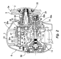
- Fig. 2 is a sectional view through the reel of Fig. 1;
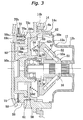
- Fig. 3 is an enlarged fragmentary view of a centrifugal braking mechanism taken from Fig. 2;
- Fig. 4 is an exploded oblique view depicting components of the centrifugal braking mechanism; and
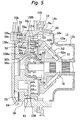
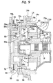
- Fig. 5, 6, 7, 8 and 9 are views of the centrifugal braking mechanism each corresponding to Fig. 3, in respective further embodiments of the present invention.
-
- Reference is made to Fig. 1, the plan view of a dual-bearing reel in which an embodiment according to the present invention is adapted.
- The dual-bearing reel shown in the figure is a bait reel used mainly for lure fishing and includes a
reel body 1, ahandle 2, and astar drag 3. Thehandle 2 is provided for rotating the spool and is disposed on one side of thereel body 1. Thestar drag 3 is disposed on the reel-body side of thehandle 2. Thehandle 2 is a dual-handle type that includes a plate-type arm portion 2a and holdingportions 2b, each of which is rotatably fitted to a respective end of thearm portion 2a. The outer surface of thearm portion 2a of thehandle 2 is a smooth seamless surface to keep fishing line from getting tangled on it. - As shown in Fig. 2, the
reel body 1 includes aframe 5, a first side-cover 6, a second side-cover 7, and afront cover 10. Thefirst side cover 6 and the second side cover 7 are disposed on respective sides of thereel frame 5. Thefront cover 10 is disposed to be open/closable on a front portion of theframe 5. Theframe 5 includes a pair ofside plates 8 and 9, which are disposed opposite each other at a predetermined spacing, and a plurality of (not shown) connecting members, each of which connects theside plates 8 and 9. - The second side cover 7, which is located on the
handle 2 end, is detachably fastened to theside plate 9 by screws. Thefirst side cover 6, which is located on the opposite end of thehandle 2, is detachably fitted to the side plate 8 by abayonet coupling 14. Anopening 8a, through which thespool 12 penetrates, is formed in the side plate 8 located on the opposite end of thehandle 2. - Inside the
frame 5, are thespool 12, alevel wind mechanism 15, and athumb rest 17. Thelevel wind mechanism 15 is provided for uniformly winding on fishing line around thespool 12. Thethumb rest 17 on which the thumb is rested during a thumb-actuated operation is also used as a clutch lever. Agear mechanism 18, a clutch mechanism 13, a clutch engage/disengage mechanism 19, adrag mechanism 21, and acasting control mechanism 22 are provided in the space between theframe 5 and the second side-cover 7. Thegear mechanism 18 transmits rotational force from thehandle 2 to thespool 12 and thelevel wind mechanism 15. The clutch engage/disengage mechanism 19 engages/disengages the clutch mechanism 13 in accordance with operation of thethumb rest 17. Thedrag mechanism 21 brakes thespool 12 when fishing line is released. Thecasting control mechanism 22 brakes thespool 12 by grasping the spool'sspindle 16 at either end. Also, acentrifugal braking mechanism 23 for preventing backlash during casting is provided between theframe 5 and the first side-cover 6. - The
spool 12 on either side has saucer-shapedflange portions 12a, and between theflange portions 12a has tubular line-windingtrunk 12b. Also, thespool 12 has atubular boss portion 12c that is formed integral with the inner peripheral side of the line-windingtrunk 12b in the middle. By for example, a serration engagement thespool 12 is non-rotatably fixed to thespool spindle 16, which penetrates through theboss portion 12c. - The
spool spindle 16 penetrates theside plate 9 and extends outside the second side-cover 7. The extended end of thespool spindle 16 is rotatably supported on abearing 35b in aboss 29 that is formed in the second side cover 7. Also, bearing 35a in thecentrifugal braking mechanism 23 rotatably supports the other end of thespool spindle 16. - The
level wind mechanism 15 includes a guide tube 25, aworm shaft 26, and aline guide 27. The guide tube 25 is fixed between the pair ofside plates 8 and 9. Theworm shaft 26 is rotatably supported in the guide tube 25. Agear 28a, which forms a part of thegear mechanism 18, is fixed to one end of theworm shaft 26. Also, aspiral groove 26a is formed on theworm shaft 26, and theline guide 27 is meshed with thespiral groove 26a. Theline guide 27 therefore reciprocates along the guide tube 25 by theworm shaft 26 being rotated via thegear mechanism 18. A fishing line is inserted in theline guide 27 and uniformly wound onto thespool 12. - The
gear mechanism 18 includes amain gear 31, apinion gear 32, the above-mentionedgear 28a, and agear 28b. Themain gear 31 is coupled to ahandle shaft 30. Thepinion gear 32 is cylindrical and is engaged with themain gear 31. Thegear 28a is fixed to one end of theworm shaft 26. Thegear 28b is non-rotatably fixed to thehandle shaft 30 and engaged with thegear 28a. - The
pinion gear 32, a cylindrical member disposed outward of theside plate 9, is centrally penetrated by thespool spindle 16. Thepinion gear 32 is fitted to be axially shiftable on thespool spindle 16. Thepinion gear 32 includes atoothed portion 32a and an meshingportion 32b. Thetoothed portion 32a is located on the right side of thereel body 1 shown in Fig. 2 and engages with themain gear 31. The meshingportion 32b is formed at the other of thepinion gear 32. Aconstricted portion 32c is established between thetoothed portion 32a and the meshingportion 32b. The meshingportion 32b is constituted by a recessed groove formed on the end face of thepinion gear 32, and aclutch pin 16a, which radially penetrates thespool spindle 16, engages in the meshingportion 32b. Shifting thepinion gear 32 outward detaches theclutch pin 16a on thespool spindle 16 from the recessed groove in the meshingportion 32b, such that rotation from thehandle shaft 30 is not transmitted to thespool 12. The clutch mechanism 13 is constituted by the recessed groove of the meshingportion 32b and theclutch pin 16a. - As shown in Fig. 2, the
thumb rest 17 is disposed at the back of thespool 12 in the rear part between the pair ofside plates 8 and 9. Thethumb rest 17 is also used as a clutch operation lever. An oblong hole (not shown) is formed in theside plates 8 and 9 of theframe 5, and a clutch cam (not shown) that fixes thethumb rest 17 penetrates the oblong hole. Thus, thethumb rest 17 slides up and down along the oblong hole. The clutch engage/disengage mechanism 19 includes a clutch yoke 40. By turning movement of thethumb rest 17, the clutch engage/disengage mechanism 19 shifts the clutch yoke 40 parallel to the axis of thespool spindle 16. Further, when thehandle shaft 30 is rotated in the line reeling-in direction, the clutch engage/disengage mechanism 19 shifts the clutch yoke 40 whereby the clutch mechanism 13 is automatically put on. - In the configuration thus, the
pinion gear 32 is normally located at a clutch engaging position and the meshingportion 32b is engaged with theclutch pin 16a for thespool spindle 16 to achieve a clutch-on state. On the other hand, when thepinion gear 32 is moved outwardly by the clutch yoke 40, the meshingportion 32b is disengaged from theclutch pin 16a to achieve a clutch-off state. - In the configuration thus, the
pinion gear 32 is the usual state is situated in the inward clutch-engaging position wherein the meshingportion 32b is engaged with theclutch pin 16a in thespool spindle 16, which is the clutch-on state. On the other hand, when the clutch yoke 40 shifts thepinion gear 32 outward, engagement of the meshingportion 32b and theclutch pin 16a is released, which is the clutch-off state. - As shown in Fig. 3, the
centrifugal braking mechanism 23 includes shiftingmembers 52, abrake element 53, an urgingmember 54, a restrictingmember 55, and an urging i force adjustingmechanism 56. The shiftingmembers 52 are provided on arotary member 51 that rotates linked with thespool 12. Thebrake element 53 is capable of coming into contact with the shiftingmembers 52. The urgingmember 54 urges thebrake element 53 towards the shiftingmembers 52. The restrictingmember 55 restricts travel of thebrake element 53 towards the shiftingmembers 52. The urgingforce adjusting mechanism 56 adjusts the urging force of the adjustingmember 54. - The shifting
members 52, members fitted to permit shifting on therotary member 51, travel radially and axially outward under centrifugal force from rotation of thespool 12. Therotary member 51 is a cylindrical component non-rotatably coupled to thespool spindle 16 by, for instance, a serration coupling.Guide shafts 57, which may number six for example, are disposed circumferentially spaced on the outer peripheral surface of therotary member 51. The radially fittedguide shafts 57 incline towards thebrake element 53. Each shiftingmember 52 is provided in arespective guide shaft 57 and permitted axial travel therein. By thus disposing theguide shafts 57 radially, at an incline, the shiftingmembers 52 shift diagonally-radially and axially outward--along theguide shafts 57 under centrifugal force, when centrifugal force acts on the shiftingmembers 52. Aflange portion 51a for preventing the shiftingmembers 52 from coming off is disposed at an end (the left end in Fig. 3) of therotary member 51. - The shifting
members 52 are approximately rod-shaped components that bend towards thebrake element 53.Guide holes 52a in which theguide shafts 57 are guided are formed in the shiftingmembers 52. Contact surfaces 52b lying in a plane orthogonal to thespool spindle 16 are formed on the ends of the shiftingmembers 52 on thebrake element 53 side. The shiftingmembers 52 are non-rotatable with respect to theguide shafts 57 in order that the contactingsurfaces 52b stay lying in the just-mentioned orthogonal plane. - As shown in Fig. 3 and 4, the
brake element 53 is provided non-rotatably on thereel body 1, yet allowed axial travel with respect to thespool 12. Thebrake element 53 is a washer-shaped component able to come into contact with the shiftingmembers 52 shifted under centrifugal force. In practice, thebrake element 53 is fitted non-rotatably yet permitted to shift axially in abrake case 50 that forms part of thereel body 1. Thebrake case 50, a short cylindrical component having base, is formed with a cylindrical bearing-accommodation portion 50a that projects inwardly from the central portion of the base. The inner periphery of the bearingaccommodating portion 50a, to which a friction plate of thecasting control mechanism 22 is attached, accommodates thebearing 35a that supports thespool spindle 16. Thebrake element 53 is non-rotatably fitted to and permitted axial travel on the outer periphery of the bearingaccommodating portion 50a. - The brake case 50 (as shown in Fig. 2) is fixed to the
first side cover 6 by ascrew 60. Namely, thebrake case 50 forms a part of thereel body 1. Also, a pair of mortise-grooves 50b are formed running axially on the outer periphery of the end (right end in Fig. 3) of the bearingaccommodating portion 50a. The mortise-grooves 50b are provided for non-rotatably interlocking with thebrake element 53. Anannular groove 50c is formed at the end of the mortise-grooves 50b, and the restrictingmember 55 is fitted in theannular groove 50c. The restrictingmember 55 is, for example, an elastic ring-shaped element made of wire with a portion of the circle notched and, as described above, restricts travel of thebrake element 53 towards the shiftingmembers 52. Being that the inner periphery of thebrake element 53 is supported on the bearingaccommodating portion 50a to permit it axial shift, a pair ofinterlock projections 53a that interlock with the mortise-grooves 50b is formed on the inner periphery. - Three
projections 14a that are components of thebayonet coupling 14 are formed circumferentially spaced on the outer surface of thebrake case 50. Also,pawls 14b are formed on theopening 8a in positions opposite theprojections 14a. The pawls are formed projecting 14b outwardly from theopening 8a. - The urging
member 54 is a conical spring one end of which abuts on thebrake element 53--the larger diameter end is on thebrake element 53 side. The urgingmember 54 is disposed between thebrake element 53 and a pressingmember 58, which will be described later, in a compressed state. It should be understood that the urgingmember 54 may be at its free length when the pressingmember 58 is most retracted. - The urging
force adjusting mechanism 56 includes the pressingmember 58, anoperation member 59, and acam mechanism 61. The pressingmember 58 is disposed non-rotatably yet permitting axial shift in thebrake case 50. Theoperation member 59 is pivotably fitted to the exterior of the brake case. Thecam mechanism 61 converts pivoting of theoperation member 59 into axial shifting of the pressingmember 58. - The pressing
member 58 includes an innerperipheral part 58a, an outerperipheral part 58b, and abase 58c. The innerperipheral part 58a is supported to permit axial shift on the bearingaccommodating portion 50a. The outerperipheral part 58b is non-rotatably fitted yet permitted axial shift on inner surface of thebrake case 50. Thebottom portion 58c connects the innerperipheral part 58a and the outerperipheral part 58b. A pair of radially protruding interlock pins 62 is formed on the outer surface of the outerperipheral part 58b. The pair of interlock pins 62 interlocks with a pair ofinterlock grooves 50e formed in the inner peripheral surface of thebrake case 50 along the spool spindle direction to fit the pressingmember 58 non-rotatably to thebrake case 50. Also, afirst cam 63 of thecam mechanism 61 is formed on the outer peripheral surface of the outerperipheral part 58b. Thefirst cam 63 is roughly triangular. A steppedportion 58d is formed on the inner wall of thebottom portion 58c, and the other end of the urgingmember 54 is interlocked on the steppedportion 58d. - The
operation member 59, an approximately ring-shaped component, is rotatively fitted to the outer end face of thebrake case 50. Aknob 59a is formed on the outer periphery of the outer end face of theoperation member 59. Theknob 59a is formed protruding in the spool axial outward direction. A central projectingportion 59c running diametrically is further formed on the outer surface of theknob 59a so as to protrude from the surface of thefirst side cover 6. The projectingportion 59c for indicating a number from 0 to 5 (not depicted in the figures), for instance, on the surface of thefirst side cover 6 to signify braking force strength. Also, a pair of pivot-restrictingrecesses 59b for restricting pivotal range of the operation member is formed on the inner peripheral face thereof. Apositioning mechanism 70 for positioning pivotal angle with respect to thebrake case 50 into six positions is provided in theoperation member 59. - The
positioning mechanism 70 includes apositioning pin 70a, acoil spring 70b, andpositioning recesses 70c. Thepositioning pin 70a is attached to theoperation member 59 movably in the spool axis direction. Thecoil spring 70b urges thepositioning pin 70a toward thebrake case 50 side. The positioning recesses 73c, which number six in this embodiment, are formed circumferentially spaced on the outer lateral face of thebrake case 50. -
Second cams 64, which form a part of thecam mechanism 61, are provided on the right hand side surface of theoperation member 59 in Fig. 4. Each of thesecond cams 64 is formed at a position corresponding to the position of the respectivefirst cam 63, and forms a triangular oblique side cam. The rotation of theoperation member 59 is converted into a movement of the pressingmember 58 in a direction approaching to thebrake element 53. Also, a pair ofcam grooves 50f having an arc shape is provided in thebrake case 50 for the respectivesecond cam 64 to penetrate. - The
operation member 59 is compressed against thebrake case 50 by apressing plate 75. Thepressing plate 75 compresses theoperation member 70 by means of screws, each of which is tighten against a respectivescrew base portion 50d formed on the outer side surface of thebrake case 50. Thescrew base portion 50d protrudes outwardly in the radius direction. The range of the rotational angle of theoperation member 59 is predetermined by thescrew base portions 50d which stops the movement of theoperation member 59 by being engaged with the respective rotation controllingconcave portion 59b. - In the urging
force adjusting mechanism 56 having the above-mentioned configuration, the pressingmember 58 moves in a direction approaching thebrake element 53 due to the function of the first andsecond cams operation member 59 is rotated, using theknob portion 59a, in the direction indicate by an arrow A . As a result, the braking force is increased since the urging force against thebrake element 53 is increased and the reaction force generated when the shiftingmembers 52 make contact with thebrake element 53 is increased. On the other hand, when theoperation member 59 is rotated in the direction indicated by an arrow B , the pressingmember 58 is moved in a direction away from thebrake element 53 by the urging force of the urgingmember 54 and, hence, the urging force applied to thebrake element 53 is reduced. Accordingly, the braking force is reduced. When the pressingmember 58 is moved to a most receded position, the braking force reaches its minimal and the reaction force is gradually decreased from one position to the other among four intermediate positions. Accordingly, the braking force is decreased stepwise. - In this embodiment, since the braking force is adjusted by changing the urging force of the urging
member 54, the braking force may be easily adjusted and a distinctive difference in the braking force may be obtained by the adjustment of the urging force. - In a normal state, the clutch yoke 40 is pressed inwardly and, hence, a clutch-on state is maintained. As a result, the rotational force from the
handle 2 is transmitted to thespool 12 via thehandle shaft 30, themain gear 31, thepinion gear 32 and thespool spindle 16 to rotate thespool 12 in the line reeling-in direction. At that time, although centrifugal force acts on the shiftingmembers 52 of thecentrifugal braking mechanism 23 to move the shiftingmembers 52 outwardly in the radius direction and the axial direction, the braking force does not become so large since the rotation speed of thespool 12 is low and, hence, it does not interfere with the rotation of thehandle 2. However, if it is necessary to reduce the braking force, theoperation member 59 may be rotated in the direction indicated by the arrow B in Fig. 4 using theknob portion 59a so that the pressing member may be positioned at a receded position shown in Fig. 3. - When a fishing line is cast, the braking force is adjusted to prevent backlash by the
operation member 59 using theknob portion 59a. When the pressingmember 58 is moved towards thebrake element 53 by rotating theoperation member 59 in the direction indicated by the arrow A, the urging force of the urgingmember 54 is increased and the braking force is enhanced. - Then, the
thumb rest 17 may be pushed down. In this embodiment, thethumb rest 17 is moved along theside plates 8 and 9 down to a disengaging position located below. Due to the movement of thethumb rest 17, the clutch yoke 40 and thepinion gear 32 are moved outwardly. As a result, the clutch enters a clutch-off state. In the clutch-off state, the rotation from thehandle shaft 30 is not transmitted to neither thespool 12 nor thespool spindle 16 and thespool 12 may freely rotate. When a fishing rod is swung in the clutch-off state so that a reel is inclined in the axis direction in order for thespool spindle 16 to face a vertical surface while thumbing the spool using a thumb on thethumb rest 17, a lure is cast and thespool 12 rotates vigorously in the line-releasing direction. - In this state, the
spool spindle 16 is rotated in the line-releasing direction by the rotation of thespool 12, and the rotation is transmitted to therotary member 51. When therotary member 51 is rotated, the shiftingmembers 52 make contact with thebrake element 53, and thespool 12 is braked by thecentrifugal braking mechanism 23 to prevent a generation of backlash. - In addition, if backlash of the
spool 12 is caused by any chance, the problem may be easily dissolved since thefirst side cover 6 is easily removed due to the presence of thebayonet coupling 14. - Moreover, if the lure is changed to one having a different weight, the braking force may be adjusted in accordance with the weight of the lure, by rotating the
operation member 59 using theknob portion 59a. In this embodiment, the braking force is easily adjusted by simply rotating theoperation member 59 using theknob portion 59a which is exposed to outside of the reel. Further, a clear difference in the braking force may be obtained when the braking force is adjusted. -
- (a) Although the pressing
member 58 is shifted by thecam mechanism 61 in the above-described embodiment, the pressingmember 58 may be shifted through other converting mechanisms such as screws. - (b) The
brake element 53 may be urged by an urgingmember 154 formed by a plurality of coil springs 54a through 54d, as shown in Fig. 5. In this embodiment, the coil springs 54a through 54d are each of different free length and diameter, and disposed concentrically nested. The free length of the coil spring 54a on the outer circumferential side is the longest and that of thecoil spring 54d on the inner circumferential side is the shortest. Also, the position of the tip-end of thecoil spring 54d on the inner circumferential side located to enable contact with thebrake element 53 when most retracted. The pressingmember 158 in this embodiment includesinner portion 158a,outer portion 158b, andbase portion 158c.Cylindrical interlock projections 58e for interlocking with the base ends of the coil springs 54a through 54d are provided on the [pressing member 58]base portion 158c. In this embodiment, since thebrake element 53 makes contact with each coil spring 54a through 54d stepwise, the urging force changes stepwise, not continuously, and, hence, the braking force also varies stepwise. Accordingly, a distinctive difference in the braking force may be obtained by adjusting the urging force. - (c) As shown in Fig. 6, it is possible to dispose an
urging
member 71 at the right hand side of thebrake element 53 in Fig. 6. The urgingmember 71 may be a cone shaped coil spring whose diameter becomes larger towards thebrake element 53 side. The spring constant of the urgingmember 71 is smaller than that of the urgingmember 54 and the urging force at a normal state of the urgingmember 71 is also smaller than that of the urgingmember 54. An end portion of the urgingmember 71 at the smaller diameter side is engaged with aspring engaging ring 73 which is controlled by a stop ring 72 being engaged with theannular groove 50c. In this embodiment, the urging force of the urgingmember 54 is adjusted by using the urgingforce adjusting mechanism 56 so that it becomes stronger than the urging force of the urgingmember 71. When it is desired to freely rotate thespool 12, the urging force of the urgingmember 54 is adjusted so that it becomes weaker than the urging force of the urgingmember 71. In this manner, thebrake element 53 may be surely separated from the shiftingmembers 52 by the urging force of the urgingmember 71. As a result, the braking force is not applied to thespool 12 and, hence, thespool 12 may surely rotate in a free state. - (d) As shown in Fig. 7, guide
shafts 157 may be radially disposed inguide holes 152a extending along the radius direction ofrotary member 151, and a conicalinclined braking surface 53b may be formed onbrake element 153. Herein, shiftingmembers 152 are movably guided in the radius direction of therotary member 51. Contact faces 152b formed with sloping bent surfaces so as to contact the braking face are formed on the ends of the shiftingmembers 152. In the embodiment thus, when thespool 12 is rotated and centrifugal force acts on the shiftingmembers 152, the shiftingmembers 152 move outwardly in the radius direction to make contact with theinclined braking surface 53b. Accordingly, thespool 12 is braked. Therein, since theinclined braking surface 53b is inclined, thebrake element 153 is pressed outwardly in the spool axis direction by the shiftingmembers 152. The braking force in this instance is determined by the urging force of the urgingmember 54 urging thebrake element 53 towards the shiftingmembers 152. Herein, the structure for attaching the shiftingmembers 152 is simplified because the shiftingmembers 152 need only shift radially. - (e) As shown in Fig. 8, shifting
members 252 may be configured with two elements, a first shiftingmember 76 allowed to shift axially, and asecond shifting members 77 allowed to shift radially. -
- The first shifting
member 76 is, for instance, a circular truncated conical member provided non-rotatably, yet permitted axial shift, onrotary member 151. An annular contact portion 76a is formed on the end of the first shiftingmember 76 on the large- diameter side. An extension member 74 made out of a coil spring interlocks with the other end on the small-diameter side. The extension member 74 pulls the first shiftingmember 76 towardsspool 112. For this purpose, the ends of the extension member 74 are interlocked with the first shiftingmember 76 as well as thespool 112. It should be noted that the tensile force of the extension member 74 is weaker than, for example, the axially outward component force acting under centrifugal force on the first shiftingmember 76 when centrifugal force acts on thesecond shifting members 77 during line reel-out, and larger than the axially outward component force acting during the line reeling-in operation. - The
second shifting members 77 are fitted to the first shiftingmember 76 allowing them to shift radially. The ends of thesecond shifting members 77 arefaces 77a sloped for contact on atapered surface 112d formed on the outer peripheral surface of theflange portion 112a of thespool 112. - In the embodiment thus, when the
spool 112 rotates and centrifugal force acts on thesecond shifting members 77, thesecond shifting members 77 shift radially outward under the centrifugal force and contact thetapered surface 112d. When thesecond shifting members 77 come into contact with the taperedsurface 112d, they shift axially outward together with the first shiftingmember 76 at the point when the axial component force arising due to the centrifugal force becomes larger than the tensile force of the extension member 74. As a result, the first shiftingmember 76 comes into contact with thebrake element 53 to brake the spool. When the component force due to the centrifugal force becomes weaker than the tensile force the first shiftingmember 76 is pulled by the extension member 74 and parted from thebrake element 53. Further, thespool 112 is not braked when rotated at the speeds during line reel-in that are lower than during line reel-out, because when reeling in line the component force that arises under centrifugal force is weaker than the tensile force of the extension member 74. Thespool 112 is therefore selectively braked during line reel-in and during line reel-out. - In addition, as shown in Fig. 9, guide
shafts 80 may be provided radially on first shifting member 78 provided non-rotatably yet permitted axial shift on therotary member 51. Second shifting members 79 permitted radial movement may be provided on theguide shafts 80. Formed on the second shifting members 79 are first contact surfaces 79a that come into contact with the taperedsurface 112d of thespool 112, and second contact surfaces 79b that come into contact with thebrake element 53. Operation in this case is likewise as with the embodiment illustrated in Fig. 8; explanation is therefore omitted. - (f) In the above embodiment, although the shifting members are provided on the rotary member in a movable manner in the radius direction and/or the axial direction, the shifting members may be pivotally provided on the rotary member so the they are pivoted by the centrifugal force.
- (g) In the above embodiment, although the shifting
members are provided on the rotary member which rotates
together with the
spool 12, the shifting members maybe directly attached to thespool 12. -
- According to the present invention, since the braking force is adjusted by changing the urging force of the first urging member, the braking force may be adjusted easily and a distinctive difference in the braking force may be obtained by the adjustment of the urging force.
- While only selected embodiments have been chosen to illustrate the present invention, to those skilled in the art it will be apparent from this disclosure that various changes and modifications can be made herein without departing from the scope of the invention as defined in the appended claims. Furthermore, the foregoing description of the embodiments according to the present invention is provided for illustration only, and not for the purpose of limiting the invention as defined by the appended claims.
Claims (9)
- A centrifugal braking device for a dual-bearing reel having a reel body (1) with a spool (12) provided rotatively on an axle, wherein said braking device is adapted to brake the spool (12) by centrifugal force, said dual-bearing reel centrifugal braking device comprising:shifting members (52, 152, 252) provided on one selected from the spool (12) and a rotary member (51, 151) rotating linked with the spool (12), said shifting members (52, 152, 252) shifting under centrifugal force due to rotation of said spool (12) ;a brake element (53) non-rotatably provided in the reel body (1) yet permitted travel in the axial direction of said spool (12), said brake element (53) adapted for contact with said shifting members (52, 152, 252) shifted under centrifugal force;a first urging member (54) for urging said brake element (53) towards said shifting members (52, 152, 252) ;a restricting member (55) for regulating travel of said brake element (53) towards said shifting members (52); and an urging force adjusting mechanism (56) for adjusting urging force of said first urging member (54).
- The dual-bearing reel centrifugal braking device as claimed in claim 1, further comprising: a second urging member (71) for urging said brake element (53) in a direction parting from said shifting members (52), wherein urging force of said second urging member (71) is smaller than urging force of said first urging member (54).
- The dual-bearing reel centrifugal braking device as claimed in claim 1 or claim 2 wherein said shifting members (52) shifting under centrifugal force in the axial direction of said spool (12) press on said brake element (53) in said axial direction.
- The dual-bearing reel centrifugal braking device set forth in any preceding claim wherein:said shifting members (52) are fitted to guide shafts (57) provided standing radially on said one selected from the spool (12) and a rotary member (51) rotating linked with the spool (12), and incline endwise toward said brake element (53); andsaid shifting members (52) endwise have contact portions (52b) lying in a plane orthogonal to the axial direction of said spool (12).
- The dual-bearing reel centrifugal braking device set forth in any preceding claim wherein:
said shifting members (52) shift radially of said spool (12) under centrifugal force; and said brake element (53) is pressed in said axial direction when said shifting members (52) come into contact therewith. - The dual-bearing reel centrifugal braking device set forth in any preceding claim wherein said shifting members (252) include:first member parts (76) provided non-rotatably, yet permitted to shift axially, on said one selected from the spool (12) and a rotary member (151) rotating linked with the spool (12), said first member parts (76) for contact with said brake element (53) ;second member parts (77) provided to permit radial shifting on said first member parts (76), wherein by radial travel said second member parts (77) shift said first member parts (76) towards said brake element (53) and;a third urging member (74) for urging said first member parts (76) in a direction parting from said brake element (53).
- The dual-bearing reel centrifugal braking device as claimed in any preceding claim wherein said shifting members (151) include:first member parts (76) provided non-rotatably, yet permitted to shift axially, on said one selected from the spool (12) and a rotary member (151) rotating linked with the spool (12);second member parts (77) provided to permit radial shifting on said first member parts (76) wherein by radial travel said second member parts (77) shift together with said first member parts (76) in said axial direction into contact with said brake element (53) and;a third urging member (74) for urging said first member parts (76) in a direction parting from said brake element (53).
- The dual-bearing reel centrifugal braking device as claimed in any preceding claim wherein said first urging member (54) includes a plurality of nested concentric coil springs (54a, 54b, 54c, 54d) differing in free length and coil diameter.
- A centrifugal braking device for a dual-bearing fishing reel having a line-winding spool (12) spinning on a spindle (16) clutch-engagable to and disengagable from a line-winding handle (2) in one bearing end of the reel, wherein said braking device is adapted to selectively brake the spool, said centrifugal braking device comprising:a rotary member (51) mechanically linked to the spool (12) for rotation together therewith;a centrifugally shifting member (52) supported on said rotary member (51) in a configuration enabling said shifting member (52), under centrifugal force of the spool (12) when spinning, to shift along a direction having axial and radial components with respect to said rotary member (51), said shifting member (52) therein being provided with axial and radial braking contact faces (52b) intersecting said axial and radial components;a brake disk (53) fitted non-rotatably to and permitted axial travel on a bearing-accommodating portion (50a) of a brake case (50) accommodating the other bearing-end of the reel, for axial braking contact with the axial braking contact face of said shifting member (52);a radial braking surface configured for radial braking contact with the radial braking contact face of said shifting member (52).a compressive urging member (54) for urging said brake disk (53) towards said axial braking contact face of said shifting member (52);an extensive urging member (74) interlocked endwise with said shifting member (52) to draw said shifting member (52) towards the spool (12);a regulating element (55) for regulating axial travel of said brake element (53) towards said shifting members (52); andan urging force adjusting mechanism (56) for adjusting urging force of said compressive urging member (54) on said brake disk (53);wherein tensile force of said extensive urging member (74) is predetermined to be smaller than the axial component of centrifugal force acting on said shifting member (52) when the spool (12) is spinning clutch-disengaged from the handle (2), and to be larger than the axial component of centrifugal force acting on said shifting member (52) when the spool (12) is spinning clutch-engaged to the handle (2).
Applications Claiming Priority (2)
| Application Number | Priority Date | Filing Date | Title |
|---|---|---|---|
| JP16939399 | 1999-06-16 | ||
| JP11169393A JP2000354442A (en) | 1999-06-16 | 1999-06-16 | Centrifugal braking device for dual bearing reel |
Publications (2)
| Publication Number | Publication Date |
|---|---|
| EP1060664A1 true EP1060664A1 (en) | 2000-12-20 |
| EP1060664B1 EP1060664B1 (en) | 2003-09-17 |
Family
ID=15885777
Family Applications (1)
| Application Number | Title | Priority Date | Filing Date |
|---|---|---|---|
| EP00305085A Expired - Lifetime EP1060664B1 (en) | 1999-06-16 | 2000-06-15 | Dual-bearing reel centrifugal braking device |
Country Status (10)
| Country | Link |
|---|---|
| US (1) | US6196485B1 (en) |
| EP (1) | EP1060664B1 (en) |
| JP (1) | JP2000354442A (en) |
| KR (1) | KR20010066838A (en) |
| AT (1) | ATE249736T1 (en) |
| DE (1) | DE60005248T2 (en) |
| ES (1) | ES2206141T3 (en) |
| MY (1) | MY123989A (en) |
| SG (1) | SG82082A1 (en) |
| TW (1) | TW448033B (en) |
Cited By (2)
| Publication number | Priority date | Publication date | Assignee | Title |
|---|---|---|---|---|
| CN105309400A (en) * | 2014-07-16 | 2016-02-10 | 株式会社岛野 | Dual-bearing reel |
| US20230276780A1 (en) * | 2020-08-27 | 2023-09-07 | Globeride, Inc. | Fishing reel, and its braking device and braking system |
Families Citing this family (13)
| Publication number | Priority date | Publication date | Assignee | Title |
|---|---|---|---|---|
| JP3747429B2 (en) * | 1999-07-07 | 2006-02-22 | 株式会社シマノ | Double bearing reel braking device |
| TW462872B (en) * | 1999-07-26 | 2001-11-11 | Shimano Kk | Centrifugal braking apparatus of double-bearing reel |
| KR100320399B1 (en) * | 1999-09-02 | 2002-01-15 | 현광호 | Braice construction for fishing reel |
| JP3535781B2 (en) * | 1999-10-28 | 2004-06-07 | ダイワ精工株式会社 | Fishing reel |
| US7552886B2 (en) | 2007-07-10 | 2009-06-30 | W.C. Bradley/Zebco Holdings, Inc. | Double drag, pre-set adjust and unitary end assembly for trolling reel |
| JP5124435B2 (en) * | 2008-12-16 | 2013-01-23 | 株式会社シマノ | Double bearing reel |
| US20110079672A1 (en) * | 2009-10-07 | 2011-04-07 | Hyunkyu Kim | Automatic external adjustable spool braking system |
| JP5718119B2 (en) * | 2011-03-29 | 2015-05-13 | 株式会社シマノ | Centrifugal braking device for double-bearing reel |
| JP5926564B2 (en) * | 2012-01-18 | 2016-05-25 | 株式会社シマノ | Double-bearing reel spool braking device and double-bearing reel |
| CN103380765B (en) * | 2012-05-04 | 2015-02-04 | Doyo工程有限公司 | Fishing reel having centrifugal brake system |
| JP6846156B2 (en) * | 2016-10-19 | 2021-03-24 | 株式会社シマノ | Double bearing reel |
| CN112772588B (en) * | 2019-11-07 | 2024-06-28 | 威海亿美运动器械有限公司 | Electric fishing reel and brake structure thereof |
| TWI924881B (en) * | 2021-11-24 | 2026-05-11 | 日商島野股份有限公司 | Drum braking device for biaxial bearing winding machine |
Citations (3)
| Publication number | Priority date | Publication date | Assignee | Title |
|---|---|---|---|---|
| JPH10304798A (en) | 1997-03-06 | 1998-11-17 | Ryobi Ltd | Centrifugal braking device for double bearing reel |
| JPH1175643A (en) * | 1997-09-04 | 1999-03-23 | Shimano Inc | Centrifugal braking device for dual bearing reel |
| JPH11299402A (en) * | 1998-04-21 | 1999-11-02 | Ryobi Ltd | Centrifugal braking device for double bearing reel |
Family Cites Families (8)
| Publication number | Priority date | Publication date | Assignee | Title |
|---|---|---|---|---|
| US4195721A (en) * | 1976-01-26 | 1980-04-01 | Shea Inventive Designs, Inc. | Torque exchange coupling |
| GB1576950A (en) * | 1977-06-30 | 1980-10-15 | Brooke Bond Vending Syst | Cup selection apparatus for beverage vending machine of the in-cup type |
| JP2538904Y2 (en) * | 1991-07-10 | 1997-06-18 | 株式会社シマノ | Centrifugal brake mechanism for fishing reel |
| US5996921A (en) * | 1997-03-06 | 1999-12-07 | Ryobi Limited | Centrifugal braking apparatus for baitcasting reel |
| US6086005A (en) * | 1997-03-11 | 2000-07-11 | Daiwa Seiko, Inc. | Fishing reel with magnetic force spool rotational-speed control during spool free rotational state |
| US5950949A (en) * | 1997-04-25 | 1999-09-14 | Zebco Division Of Brunswick Corporation | Adjustable brake for baitcast reel |
| US6003798A (en) * | 1997-11-14 | 1999-12-21 | Zebco Division Of Brunswick Corporation | Adjustable brake for baitcast reel |
| US5984221A (en) * | 1998-10-21 | 1999-11-16 | Zebco Division Of Brunswick Corporation | Adjustable brake for baitcast reel |
-
1999
- 1999-06-16 JP JP11169393A patent/JP2000354442A/en active Pending
-
2000
- 2000-06-09 TW TW089111346A patent/TW448033B/en active
- 2000-06-14 US US09/593,479 patent/US6196485B1/en not_active Expired - Fee Related
- 2000-06-14 KR KR1020000032761A patent/KR20010066838A/en not_active Withdrawn
- 2000-06-14 MY MYPI20002690 patent/MY123989A/en unknown
- 2000-06-14 SG SG200003329A patent/SG82082A1/en unknown
- 2000-06-15 DE DE60005248T patent/DE60005248T2/en not_active Expired - Fee Related
- 2000-06-15 EP EP00305085A patent/EP1060664B1/en not_active Expired - Lifetime
- 2000-06-15 ES ES00305085T patent/ES2206141T3/en not_active Expired - Lifetime
- 2000-06-15 AT AT00305085T patent/ATE249736T1/en not_active IP Right Cessation
Patent Citations (3)
| Publication number | Priority date | Publication date | Assignee | Title |
|---|---|---|---|---|
| JPH10304798A (en) | 1997-03-06 | 1998-11-17 | Ryobi Ltd | Centrifugal braking device for double bearing reel |
| JPH1175643A (en) * | 1997-09-04 | 1999-03-23 | Shimano Inc | Centrifugal braking device for dual bearing reel |
| JPH11299402A (en) * | 1998-04-21 | 1999-11-02 | Ryobi Ltd | Centrifugal braking device for double bearing reel |
Non-Patent Citations (2)
| Title |
|---|
| PATENT ABSTRACTS OF JAPAN vol. 1999, no. 08 30 June 1999 (1999-06-30) * |
| PATENT ABSTRACTS OF JAPAN vol. 2000, no. 02 29 February 2000 (2000-02-29) * |
Cited By (3)
| Publication number | Priority date | Publication date | Assignee | Title |
|---|---|---|---|---|
| CN105309400A (en) * | 2014-07-16 | 2016-02-10 | 株式会社岛野 | Dual-bearing reel |
| US20230276780A1 (en) * | 2020-08-27 | 2023-09-07 | Globeride, Inc. | Fishing reel, and its braking device and braking system |
| US12063918B2 (en) * | 2020-08-27 | 2024-08-20 | Globeride, Inc. | Fishing reel, and its braking device and braking system |
Also Published As
| Publication number | Publication date |
|---|---|
| JP2000354442A (en) | 2000-12-26 |
| DE60005248T2 (en) | 2004-07-01 |
| ATE249736T1 (en) | 2003-10-15 |
| US6196485B1 (en) | 2001-03-06 |
| DE60005248D1 (en) | 2003-10-23 |
| SG82082A1 (en) | 2001-07-24 |
| TW448033B (en) | 2001-08-01 |
| MY123989A (en) | 2006-06-30 |
| EP1060664B1 (en) | 2003-09-17 |
| KR20010066838A (en) | 2001-07-11 |
| ES2206141T3 (en) | 2004-05-16 |
Similar Documents
| Publication | Publication Date | Title |
|---|---|---|
| EP1060664B1 (en) | Dual-bearing reel centrifugal braking device | |
| AU759992B2 (en) | Double bearing reel | |
| US6371396B1 (en) | Dual-bearing reel braking device | |
| EP1031279B1 (en) | Centrifugal braking device for double bearing reel | |
| EP1072191B1 (en) | Dual-bearing reel centrifugal braking device | |
| KR20090014961A (en) | Clutch operating member of both bearing reels | |
| TWI600604B (en) | Double-bearing reel reel brake device and dual-bearing reel | |
| US6354526B1 (en) | Single bearing fishing reel and sounding mechanism | |
| JP6284306B2 (en) | Spool braking device for double-bearing reel | |
| KR20170101098A (en) | Dual bearing fishing reel | |
| JP2014176360A5 (en) | ||
| US5277379A (en) | Spinning reel for fishing | |
| US20060006267A1 (en) | Spool assembly for a dual bearing reel | |
| EP2113170B1 (en) | Spool for spinning reel | |
| JP2014217341A5 (en) | ||
| KR20040036564A (en) | Spool for Dual-Bearing Reel | |
| US6293483B1 (en) | Braking device for dual-bearing reel | |
| US10070636B2 (en) | Spool brake device for dual-bearing reel | |
| JP6267874B2 (en) | Spool braking device for double-bearing reel | |
| JP3747431B2 (en) | Centrifugal braking device for double-bearing reel | |
| JP3747430B2 (en) | Centrifugal braking device for double-bearing reel | |
| US4695009A (en) | Bait alert for spin cast reel | |
| EP4430946A1 (en) | Triple lever drag system | |
| JP2004000272A (en) | Double bearing reel | |
| JP2004180585A (en) | Spool of spinning reel |
Legal Events
| Date | Code | Title | Description |
|---|---|---|---|
| PUAI | Public reference made under article 153(3) epc to a published international application that has entered the european phase |
Free format text: ORIGINAL CODE: 0009012 |
|
| AK | Designated contracting states |
Kind code of ref document: A1 Designated state(s): AT BE CH CY DE DK ES FI FR GB GR IE IT LI LU MC NL PT SE |
|
| AX | Request for extension of the european patent |
Free format text: AL;LT;LV;MK;RO;SI |
|
| 17P | Request for examination filed |
Effective date: 20010207 |
|
| AKX | Designation fees paid |
Free format text: AT BE CH CY DE DK ES FI FR GB GR IE IT LI LU MC NL PT SE |
|
| 17Q | First examination report despatched |
Effective date: 20021209 |
|
| GRAH | Despatch of communication of intention to grant a patent |
Free format text: ORIGINAL CODE: EPIDOS IGRA |
|
| GRAS | Grant fee paid |
Free format text: ORIGINAL CODE: EPIDOSNIGR3 |
|
| GRAA | (expected) grant |
Free format text: ORIGINAL CODE: 0009210 |
|
| AK | Designated contracting states |
Kind code of ref document: B1 Designated state(s): AT BE CH CY DE DK ES FI FR GB GR IE IT LI LU MC NL PT SE |
|
| PG25 | Lapsed in a contracting state [announced via postgrant information from national office to epo] |
Ref country code: CH Free format text: LAPSE BECAUSE OF FAILURE TO SUBMIT A TRANSLATION OF THE DESCRIPTION OR TO PAY THE FEE WITHIN THE PRESCRIBED TIME-LIMIT Effective date: 20030917 Ref country code: CY Free format text: LAPSE BECAUSE OF FAILURE TO SUBMIT A TRANSLATION OF THE DESCRIPTION OR TO PAY THE FEE WITHIN THE PRESCRIBED TIME-LIMIT Effective date: 20030917 Ref country code: LI Free format text: LAPSE BECAUSE OF FAILURE TO SUBMIT A TRANSLATION OF THE DESCRIPTION OR TO PAY THE FEE WITHIN THE PRESCRIBED TIME-LIMIT Effective date: 20030917 Ref country code: FI Free format text: LAPSE BECAUSE OF FAILURE TO SUBMIT A TRANSLATION OF THE DESCRIPTION OR TO PAY THE FEE WITHIN THE PRESCRIBED TIME-LIMIT Effective date: 20030917 |
|
| REG | Reference to a national code |
Ref country code: GB Ref legal event code: FG4D |
|
| REG | Reference to a national code |
Ref country code: CH Ref legal event code: EP |
|
| REF | Corresponds to: |
Ref document number: 60005248 Country of ref document: DE Date of ref document: 20031023 Kind code of ref document: P |
|
| REG | Reference to a national code |
Ref country code: IE Ref legal event code: FG4D |
|
| PG25 | Lapsed in a contracting state [announced via postgrant information from national office to epo] |
Ref country code: DK Free format text: LAPSE BECAUSE OF FAILURE TO SUBMIT A TRANSLATION OF THE DESCRIPTION OR TO PAY THE FEE WITHIN THE PRESCRIBED TIME-LIMIT Effective date: 20031217 Ref country code: GR Free format text: LAPSE BECAUSE OF FAILURE TO SUBMIT A TRANSLATION OF THE DESCRIPTION OR TO PAY THE FEE WITHIN THE PRESCRIBED TIME-LIMIT Effective date: 20031217 |
|
| PG25 | Lapsed in a contracting state [announced via postgrant information from national office to epo] |
Ref country code: PT Free format text: LAPSE BECAUSE OF FAILURE TO SUBMIT A TRANSLATION OF THE DESCRIPTION OR TO PAY THE FEE WITHIN THE PRESCRIBED TIME-LIMIT Effective date: 20031226 |
|
| REG | Reference to a national code |
Ref country code: SE Ref legal event code: TRGR |
|
| REG | Reference to a national code |
Ref country code: CH Ref legal event code: PL |
|
| REG | Reference to a national code |
Ref country code: ES Ref legal event code: FG2A Ref document number: 2206141 Country of ref document: ES Kind code of ref document: T3 |
|
| PGFP | Annual fee paid to national office [announced via postgrant information from national office to epo] |
Ref country code: NL Payment date: 20040603 Year of fee payment: 5 |
|
| PGFP | Annual fee paid to national office [announced via postgrant information from national office to epo] |
Ref country code: SE Payment date: 20040604 Year of fee payment: 5 |
|
| PGFP | Annual fee paid to national office [announced via postgrant information from national office to epo] |
Ref country code: FR Payment date: 20040608 Year of fee payment: 5 |
|
| PGFP | Annual fee paid to national office [announced via postgrant information from national office to epo] |
Ref country code: AT Payment date: 20040611 Year of fee payment: 5 |
|
| PG25 | Lapsed in a contracting state [announced via postgrant information from national office to epo] |
Ref country code: IE Free format text: LAPSE BECAUSE OF NON-PAYMENT OF DUE FEES Effective date: 20040615 Ref country code: LU Free format text: LAPSE BECAUSE OF NON-PAYMENT OF DUE FEES Effective date: 20040615 |
|
| PGFP | Annual fee paid to national office [announced via postgrant information from national office to epo] |
Ref country code: ES Payment date: 20040621 Year of fee payment: 5 |
|
| PG25 | Lapsed in a contracting state [announced via postgrant information from national office to epo] |
Ref country code: MC Free format text: LAPSE BECAUSE OF NON-PAYMENT OF DUE FEES Effective date: 20040630 |
|
| ET | Fr: translation filed | ||
| PLBE | No opposition filed within time limit |
Free format text: ORIGINAL CODE: 0009261 |
|
| STAA | Information on the status of an ep patent application or granted ep patent |
Free format text: STATUS: NO OPPOSITION FILED WITHIN TIME LIMIT |
|
| PGFP | Annual fee paid to national office [announced via postgrant information from national office to epo] |
Ref country code: BE Payment date: 20040813 Year of fee payment: 5 |
|
| 26N | No opposition filed |
Effective date: 20040618 |
|
| REG | Reference to a national code |
Ref country code: IE Ref legal event code: MM4A |
|
| PG25 | Lapsed in a contracting state [announced via postgrant information from national office to epo] |
Ref country code: AT Free format text: LAPSE BECAUSE OF NON-PAYMENT OF DUE FEES Effective date: 20050615 |
|
| PG25 | Lapsed in a contracting state [announced via postgrant information from national office to epo] |
Ref country code: ES Free format text: LAPSE BECAUSE OF NON-PAYMENT OF DUE FEES Effective date: 20050616 Ref country code: SE Free format text: LAPSE BECAUSE OF NON-PAYMENT OF DUE FEES Effective date: 20050616 |
|
| PG25 | Lapsed in a contracting state [announced via postgrant information from national office to epo] |
Ref country code: BE Free format text: LAPSE BECAUSE OF NON-PAYMENT OF DUE FEES Effective date: 20050630 |
|
| PG25 | Lapsed in a contracting state [announced via postgrant information from national office to epo] |
Ref country code: NL Free format text: LAPSE BECAUSE OF NON-PAYMENT OF DUE FEES Effective date: 20060101 |
|
| EUG | Se: european patent has lapsed | ||
| PG25 | Lapsed in a contracting state [announced via postgrant information from national office to epo] |
Ref country code: FR Free format text: LAPSE BECAUSE OF NON-PAYMENT OF DUE FEES Effective date: 20060228 |
|
| NLV4 | Nl: lapsed or anulled due to non-payment of the annual fee |
Effective date: 20060101 |
|
| REG | Reference to a national code |
Ref country code: FR Ref legal event code: ST Effective date: 20060228 |
|
| REG | Reference to a national code |
Ref country code: ES Ref legal event code: FD2A Effective date: 20050616 |
|
| BERE | Be: lapsed |
Owner name: *SHIMANO INC. Effective date: 20050630 |
|
| PGFP | Annual fee paid to national office [announced via postgrant information from national office to epo] |
Ref country code: DE Payment date: 20080619 Year of fee payment: 9 |
|
| PGFP | Annual fee paid to national office [announced via postgrant information from national office to epo] |
Ref country code: IT Payment date: 20080627 Year of fee payment: 9 |
|
| PGFP | Annual fee paid to national office [announced via postgrant information from national office to epo] |
Ref country code: GB Payment date: 20080618 Year of fee payment: 9 |
|
| GBPC | Gb: european patent ceased through non-payment of renewal fee |
Effective date: 20090615 |
|
| PG25 | Lapsed in a contracting state [announced via postgrant information from national office to epo] |
Ref country code: GB Free format text: LAPSE BECAUSE OF NON-PAYMENT OF DUE FEES Effective date: 20090615 |
|
| PG25 | Lapsed in a contracting state [announced via postgrant information from national office to epo] |
Ref country code: DE Free format text: LAPSE BECAUSE OF NON-PAYMENT OF DUE FEES Effective date: 20100101 |
|
| PG25 | Lapsed in a contracting state [announced via postgrant information from national office to epo] |
Ref country code: IT Free format text: LAPSE BECAUSE OF NON-PAYMENT OF DUE FEES Effective date: 20090615 |