EP1059882B1 - Integrated tissue poration, fluid harvesting and analysis device - Google Patents
Integrated tissue poration, fluid harvesting and analysis device Download PDFInfo
- Publication number
- EP1059882B1 EP1059882B1 EP99911184A EP99911184A EP1059882B1 EP 1059882 B1 EP1059882 B1 EP 1059882B1 EP 99911184 A EP99911184 A EP 99911184A EP 99911184 A EP99911184 A EP 99911184A EP 1059882 B1 EP1059882 B1 EP 1059882B1
- Authority
- EP
- European Patent Office
- Prior art keywords
- tissue
- sensor
- fluid
- integrated device
- biological fluid
- Prior art date
- Legal status (The legal status is an assumption and is not a legal conclusion. Google has not performed a legal analysis and makes no representation as to the accuracy of the status listed.)
- Revoked
Links
- 238000003306 harvesting Methods 0.000 title claims abstract description 24
- 238000004458 analytical method Methods 0.000 title claims abstract description 8
- 239000012530 fluid Substances 0.000 title claims description 96
- 210000001519 tissue Anatomy 0.000 claims abstract description 129
- 239000013060 biological fluid Substances 0.000 claims abstract description 99
- 239000000523 sample Substances 0.000 claims abstract description 64
- 239000000463 material Substances 0.000 claims abstract description 33
- 210000003722 extracellular fluid Anatomy 0.000 claims abstract description 25
- 238000000034 method Methods 0.000 claims description 44
- 239000008103 glucose Substances 0.000 claims description 36
- WQZGKKKJIJFFOK-GASJEMHNSA-N Glucose Natural products OC[C@H]1OC(O)[C@H](O)[C@@H](O)[C@@H]1O WQZGKKKJIJFFOK-GASJEMHNSA-N 0.000 claims description 33
- 230000003287 optical effect Effects 0.000 claims description 33
- 230000008569 process Effects 0.000 claims description 24
- 239000004094 surface-active agent Substances 0.000 claims description 16
- 230000008878 coupling Effects 0.000 claims description 15
- 238000010168 coupling process Methods 0.000 claims description 15
- 238000005859 coupling reaction Methods 0.000 claims description 15
- 239000000126 substance Substances 0.000 claims description 14
- 150000001875 compounds Chemical class 0.000 claims description 13
- 239000004020 conductor Substances 0.000 claims description 12
- 238000007789 sealing Methods 0.000 claims description 11
- XLYOFNOQVPJJNP-UHFFFAOYSA-N water Substances O XLYOFNOQVPJJNP-UHFFFAOYSA-N 0.000 claims description 7
- 230000007246 mechanism Effects 0.000 claims description 6
- 229920001296 polysiloxane Polymers 0.000 claims description 5
- 230000008016 vaporization Effects 0.000 claims description 5
- 238000004891 communication Methods 0.000 claims description 4
- 238000009834 vaporization Methods 0.000 claims description 4
- 230000002209 hydrophobic effect Effects 0.000 claims description 3
- 239000012491 analyte Substances 0.000 abstract description 33
- 239000000758 substrate Substances 0.000 abstract description 17
- 239000000853 adhesive Substances 0.000 abstract description 8
- 230000001070 adhesive effect Effects 0.000 abstract description 8
- 230000002165 photosensitisation Effects 0.000 abstract 7
- 239000003504 photosensitizing agent Substances 0.000 abstract 7
- 239000000049 pigment Substances 0.000 abstract 1
- 238000003556 assay Methods 0.000 description 82
- 210000003491 skin Anatomy 0.000 description 36
- 210000004369 blood Anatomy 0.000 description 24
- 239000008280 blood Substances 0.000 description 24
- 238000007726 management method Methods 0.000 description 21
- 238000005259 measurement Methods 0.000 description 20
- 230000000694 effects Effects 0.000 description 19
- 210000000434 stratum corneum Anatomy 0.000 description 17
- 238000012544 monitoring process Methods 0.000 description 15
- 210000004379 membrane Anatomy 0.000 description 12
- 239000012528 membrane Substances 0.000 description 12
- 238000013461 design Methods 0.000 description 10
- 238000005516 engineering process Methods 0.000 description 10
- 238000012545 processing Methods 0.000 description 10
- 210000002615 epidermis Anatomy 0.000 description 8
- 230000008901 benefit Effects 0.000 description 7
- 229940079593 drug Drugs 0.000 description 7
- 239000003814 drug Substances 0.000 description 7
- 230000006870 function Effects 0.000 description 7
- 230000004044 response Effects 0.000 description 7
- 230000009471 action Effects 0.000 description 6
- NOESYZHRGYRDHS-UHFFFAOYSA-N insulin Chemical compound N1C(=O)C(NC(=O)C(CCC(N)=O)NC(=O)C(CCC(O)=O)NC(=O)C(C(C)C)NC(=O)C(NC(=O)CN)C(C)CC)CSSCC(C(NC(CO)C(=O)NC(CC(C)C)C(=O)NC(CC=2C=CC(O)=CC=2)C(=O)NC(CCC(N)=O)C(=O)NC(CC(C)C)C(=O)NC(CCC(O)=O)C(=O)NC(CC(N)=O)C(=O)NC(CC=2C=CC(O)=CC=2)C(=O)NC(CSSCC(NC(=O)C(C(C)C)NC(=O)C(CC(C)C)NC(=O)C(CC=2C=CC(O)=CC=2)NC(=O)C(CC(C)C)NC(=O)C(C)NC(=O)C(CCC(O)=O)NC(=O)C(C(C)C)NC(=O)C(CC(C)C)NC(=O)C(CC=2NC=NC=2)NC(=O)C(CO)NC(=O)CNC2=O)C(=O)NCC(=O)NC(CCC(O)=O)C(=O)NC(CCCNC(N)=N)C(=O)NCC(=O)NC(CC=3C=CC=CC=3)C(=O)NC(CC=3C=CC=CC=3)C(=O)NC(CC=3C=CC(O)=CC=3)C(=O)NC(C(C)O)C(=O)N3C(CCC3)C(=O)NC(CCCCN)C(=O)NC(C)C(O)=O)C(=O)NC(CC(N)=O)C(O)=O)=O)NC(=O)C(C(C)CC)NC(=O)C(CO)NC(=O)C(C(C)O)NC(=O)C1CSSCC2NC(=O)C(CC(C)C)NC(=O)C(NC(=O)C(CCC(N)=O)NC(=O)C(CC(N)=O)NC(=O)C(NC(=O)C(N)CC=1C=CC=CC=1)C(C)C)CC1=CN=CN1 NOESYZHRGYRDHS-UHFFFAOYSA-N 0.000 description 6
- 239000011148 porous material Substances 0.000 description 6
- 238000002679 ablation Methods 0.000 description 5
- 238000010521 absorption reaction Methods 0.000 description 5
- 210000004027 cell Anatomy 0.000 description 5
- 230000008859 change Effects 0.000 description 5
- 206010012601 diabetes mellitus Diseases 0.000 description 5
- 238000010586 diagram Methods 0.000 description 5
- 238000002474 experimental method Methods 0.000 description 5
- 210000002966 serum Anatomy 0.000 description 5
- 238000012360 testing method Methods 0.000 description 5
- 239000012042 active reagent Substances 0.000 description 4
- 238000013459 approach Methods 0.000 description 4
- 238000006243 chemical reaction Methods 0.000 description 4
- 210000004207 dermis Anatomy 0.000 description 4
- 230000005284 excitation Effects 0.000 description 4
- 230000009467 reduction Effects 0.000 description 4
- 125000006850 spacer group Chemical group 0.000 description 4
- 238000009736 wetting Methods 0.000 description 4
- 102000004877 Insulin Human genes 0.000 description 3
- 108090001061 Insulin Proteins 0.000 description 3
- 230000004888 barrier function Effects 0.000 description 3
- 238000007398 colorimetric assay Methods 0.000 description 3
- 239000000975 dye Substances 0.000 description 3
- 238000010438 heat treatment Methods 0.000 description 3
- 229940125396 insulin Drugs 0.000 description 3
- 239000012071 phase Substances 0.000 description 3
- 238000011002 quantification Methods 0.000 description 3
- 238000012546 transfer Methods 0.000 description 3
- 238000013519 translation Methods 0.000 description 3
- 239000006096 absorbing agent Substances 0.000 description 2
- 230000004913 activation Effects 0.000 description 2
- 210000000601 blood cell Anatomy 0.000 description 2
- 230000001934 delay Effects 0.000 description 2
- 238000001514 detection method Methods 0.000 description 2
- 238000009792 diffusion process Methods 0.000 description 2
- 238000009826 distribution Methods 0.000 description 2
- 238000007812 electrochemical assay Methods 0.000 description 2
- 230000002708 enhancing effect Effects 0.000 description 2
- 210000003743 erythrocyte Anatomy 0.000 description 2
- 238000001704 evaporation Methods 0.000 description 2
- 230000008020 evaporation Effects 0.000 description 2
- 238000001914 filtration Methods 0.000 description 2
- 239000000499 gel Substances 0.000 description 2
- 238000001802 infusion Methods 0.000 description 2
- 238000012423 maintenance Methods 0.000 description 2
- 238000004519 manufacturing process Methods 0.000 description 2
- 230000004048 modification Effects 0.000 description 2
- 238000012986 modification Methods 0.000 description 2
- 210000004877 mucosa Anatomy 0.000 description 2
- 210000004400 mucous membrane Anatomy 0.000 description 2
- 229940124583 pain medication Drugs 0.000 description 2
- 230000035699 permeability Effects 0.000 description 2
- 230000005855 radiation Effects 0.000 description 2
- 239000007787 solid Substances 0.000 description 2
- 239000012780 transparent material Substances 0.000 description 2
- WFKWXMTUELFFGS-UHFFFAOYSA-N tungsten Chemical compound [W] WFKWXMTUELFFGS-UHFFFAOYSA-N 0.000 description 2
- 238000002604 ultrasonography Methods 0.000 description 2
- 239000002699 waste material Substances 0.000 description 2
- 208000000003 Breakthrough pain Diseases 0.000 description 1
- 102000008186 Collagen Human genes 0.000 description 1
- 108010035532 Collagen Proteins 0.000 description 1
- 208000017442 Retinal disease Diseases 0.000 description 1
- 206010038923 Retinopathy Diseases 0.000 description 1
- 206010052428 Wound Diseases 0.000 description 1
- 208000027418 Wounds and injury Diseases 0.000 description 1
- 239000002250 absorbent Substances 0.000 description 1
- 230000002745 absorbent Effects 0.000 description 1
- 230000001133 acceleration Effects 0.000 description 1
- 239000000654 additive Substances 0.000 description 1
- 230000000996 additive effect Effects 0.000 description 1
- 230000004075 alteration Effects 0.000 description 1
- XAGFODPZIPBFFR-UHFFFAOYSA-N aluminium Chemical compound [Al] XAGFODPZIPBFFR-UHFFFAOYSA-N 0.000 description 1
- 229960003965 antiepileptics Drugs 0.000 description 1
- 239000012298 atmosphere Substances 0.000 description 1
- QVGXLLKOCUKJST-UHFFFAOYSA-N atomic oxygen Chemical compound [O] QVGXLLKOCUKJST-UHFFFAOYSA-N 0.000 description 1
- 239000011324 bead Substances 0.000 description 1
- 230000009286 beneficial effect Effects 0.000 description 1
- 239000012867 bioactive agent Substances 0.000 description 1
- 239000012472 biological sample Substances 0.000 description 1
- 230000015572 biosynthetic process Effects 0.000 description 1
- 238000009529 body temperature measurement Methods 0.000 description 1
- 230000000739 chaotic effect Effects 0.000 description 1
- 239000003153 chemical reaction reagent Substances 0.000 description 1
- 239000003795 chemical substances by application Substances 0.000 description 1
- 238000002512 chemotherapy Methods 0.000 description 1
- 229920001436 collagen Polymers 0.000 description 1
- 230000002596 correlated effect Effects 0.000 description 1
- 239000007822 coupling agent Substances 0.000 description 1
- 238000003745 diagnosis Methods 0.000 description 1
- 238000012377 drug delivery Methods 0.000 description 1
- 238000001035 drying Methods 0.000 description 1
- 230000002500 effect on skin Effects 0.000 description 1
- 238000009429 electrical wiring Methods 0.000 description 1
- 230000005670 electromagnetic radiation Effects 0.000 description 1
- 239000007850 fluorescent dye Substances 0.000 description 1
- 230000004907 flux Effects 0.000 description 1
- 239000007789 gas Substances 0.000 description 1
- 239000003292 glue Substances 0.000 description 1
- 230000035876 healing Effects 0.000 description 1
- 230000036541 health Effects 0.000 description 1
- 239000000017 hydrogel Substances 0.000 description 1
- 239000007943 implant Substances 0.000 description 1
- 238000001727 in vivo Methods 0.000 description 1
- 238000007373 indentation Methods 0.000 description 1
- 208000014674 injury Diseases 0.000 description 1
- 238000009434 installation Methods 0.000 description 1
- 230000003993 interaction Effects 0.000 description 1
- 208000017169 kidney disease Diseases 0.000 description 1
- 238000001393 microlithography Methods 0.000 description 1
- 230000005012 migration Effects 0.000 description 1
- 238000013508 migration Methods 0.000 description 1
- 238000012806 monitoring device Methods 0.000 description 1
- 201000001119 neuropathy Diseases 0.000 description 1
- 230000007823 neuropathy Effects 0.000 description 1
- 235000015097 nutrients Nutrition 0.000 description 1
- 238000010943 off-gassing Methods 0.000 description 1
- 210000000056 organ Anatomy 0.000 description 1
- 230000001151 other effect Effects 0.000 description 1
- 239000001301 oxygen Substances 0.000 description 1
- 229910052760 oxygen Inorganic materials 0.000 description 1
- 210000000496 pancreas Anatomy 0.000 description 1
- 230000035515 penetration Effects 0.000 description 1
- 230000000737 periodic effect Effects 0.000 description 1
- 208000033808 peripheral neuropathy Diseases 0.000 description 1
- 230000010363 phase shift Effects 0.000 description 1
- 239000004033 plastic Substances 0.000 description 1
- 230000008092 positive effect Effects 0.000 description 1
- 238000012805 post-processing Methods 0.000 description 1
- 238000003825 pressing Methods 0.000 description 1
- 230000000644 propagated effect Effects 0.000 description 1
- 238000005086 pumping Methods 0.000 description 1
- 230000035484 reaction time Effects 0.000 description 1
- 238000011084 recovery Methods 0.000 description 1
- 230000002441 reversible effect Effects 0.000 description 1
- 238000005070 sampling Methods 0.000 description 1
- 230000009291 secondary effect Effects 0.000 description 1
- 230000035807 sensation Effects 0.000 description 1
- 230000035945 sensitivity Effects 0.000 description 1
- 238000010008 shearing Methods 0.000 description 1
- 230000035939 shock Effects 0.000 description 1
- 239000007790 solid phase Substances 0.000 description 1
- 238000003756 stirring Methods 0.000 description 1
- 238000001356 surgical procedure Methods 0.000 description 1
- 229940126585 therapeutic drug Drugs 0.000 description 1
- 239000010409 thin film Substances 0.000 description 1
- 231100000331 toxic Toxicity 0.000 description 1
- 230000002588 toxic effect Effects 0.000 description 1
- 230000008733 trauma Effects 0.000 description 1
- 229910052721 tungsten Inorganic materials 0.000 description 1
- 239000010937 tungsten Substances 0.000 description 1
- 238000010865 video microscopy Methods 0.000 description 1
- 238000010792 warming Methods 0.000 description 1
- 230000003442 weekly effect Effects 0.000 description 1
- 230000029663 wound healing Effects 0.000 description 1
Images









Classifications
-
- A—HUMAN NECESSITIES
- A61—MEDICAL OR VETERINARY SCIENCE; HYGIENE
- A61B—DIAGNOSIS; SURGERY; IDENTIFICATION
- A61B5/00—Measuring for diagnostic purposes; Identification of persons
- A61B5/15—Devices for taking samples of blood
- A61B5/151—Devices specially adapted for taking samples of capillary blood, e.g. by lancets, needles or blades
- A61B5/15134—Bladeless capillary blood sampling devices, i.e. devices for perforating the skin in order to obtain a blood sample but not using a blade, needle, canula, or lancet, e.g. by laser perforation, suction or pressurized fluids
-
- A—HUMAN NECESSITIES
- A61—MEDICAL OR VETERINARY SCIENCE; HYGIENE
- A61B—DIAGNOSIS; SURGERY; IDENTIFICATION
- A61B5/00—Measuring for diagnostic purposes; Identification of persons
- A61B5/145—Measuring characteristics of blood in vivo, e.g. gas concentration or pH-value ; Measuring characteristics of body fluids or tissues, e.g. interstitial fluid or cerebral tissue
- A61B5/14507—Measuring characteristics of blood in vivo, e.g. gas concentration or pH-value ; Measuring characteristics of body fluids or tissues, e.g. interstitial fluid or cerebral tissue specially adapted for measuring characteristics of body fluids other than blood
- A61B5/1451—Measuring characteristics of blood in vivo, e.g. gas concentration or pH-value ; Measuring characteristics of body fluids or tissues, e.g. interstitial fluid or cerebral tissue specially adapted for measuring characteristics of body fluids other than blood for interstitial fluid
- A61B5/14514—Measuring characteristics of blood in vivo, e.g. gas concentration or pH-value ; Measuring characteristics of body fluids or tissues, e.g. interstitial fluid or cerebral tissue specially adapted for measuring characteristics of body fluids other than blood for interstitial fluid using means for aiding extraction of interstitial fluid, e.g. microneedles or suction
-
- A—HUMAN NECESSITIES
- A61—MEDICAL OR VETERINARY SCIENCE; HYGIENE
- A61B—DIAGNOSIS; SURGERY; IDENTIFICATION
- A61B5/00—Measuring for diagnostic purposes; Identification of persons
- A61B5/145—Measuring characteristics of blood in vivo, e.g. gas concentration or pH-value ; Measuring characteristics of body fluids or tissues, e.g. interstitial fluid or cerebral tissue
- A61B5/14532—Measuring characteristics of blood in vivo, e.g. gas concentration or pH-value ; Measuring characteristics of body fluids or tissues, e.g. interstitial fluid or cerebral tissue for measuring glucose, e.g. by tissue impedance measurement
-
- A—HUMAN NECESSITIES
- A61—MEDICAL OR VETERINARY SCIENCE; HYGIENE
- A61B—DIAGNOSIS; SURGERY; IDENTIFICATION
- A61B5/00—Measuring for diagnostic purposes; Identification of persons
- A61B5/145—Measuring characteristics of blood in vivo, e.g. gas concentration or pH-value ; Measuring characteristics of body fluids or tissues, e.g. interstitial fluid or cerebral tissue
- A61B5/1455—Measuring characteristics of blood in vivo, e.g. gas concentration or pH-value ; Measuring characteristics of body fluids or tissues, e.g. interstitial fluid or cerebral tissue using optical sensors, e.g. spectral photometrical oximeters
-
- A—HUMAN NECESSITIES
- A61—MEDICAL OR VETERINARY SCIENCE; HYGIENE
- A61B—DIAGNOSIS; SURGERY; IDENTIFICATION
- A61B5/00—Measuring for diagnostic purposes; Identification of persons
- A61B5/15—Devices for taking samples of blood
- A61B5/150007—Details
- A61B5/150015—Source of blood
- A61B5/150022—Source of blood for capillary blood or interstitial fluid
-
- A—HUMAN NECESSITIES
- A61—MEDICAL OR VETERINARY SCIENCE; HYGIENE
- A61B—DIAGNOSIS; SURGERY; IDENTIFICATION
- A61B5/00—Measuring for diagnostic purposes; Identification of persons
- A61B5/15—Devices for taking samples of blood
- A61B5/150007—Details
- A61B5/150053—Details for enhanced collection of blood or interstitial fluid at the sample site, e.g. by applying compression, heat, vibration, ultrasound, suction or vacuum to tissue; for reduction of pain or discomfort; Skin piercing elements, e.g. blades, needles, lancets or canulas, with adjustable piercing speed
- A61B5/150061—Means for enhancing collection
- A61B5/150068—Means for enhancing collection by tissue compression, e.g. with specially designed surface of device contacting the skin area to be pierced
-
- A—HUMAN NECESSITIES
- A61—MEDICAL OR VETERINARY SCIENCE; HYGIENE
- A61B—DIAGNOSIS; SURGERY; IDENTIFICATION
- A61B5/00—Measuring for diagnostic purposes; Identification of persons
- A61B5/15—Devices for taking samples of blood
- A61B5/150007—Details
- A61B5/150053—Details for enhanced collection of blood or interstitial fluid at the sample site, e.g. by applying compression, heat, vibration, ultrasound, suction or vacuum to tissue; for reduction of pain or discomfort; Skin piercing elements, e.g. blades, needles, lancets or canulas, with adjustable piercing speed
- A61B5/150061—Means for enhancing collection
- A61B5/150083—Means for enhancing collection by vibration, e.g. ultrasound
-
- A—HUMAN NECESSITIES
- A61—MEDICAL OR VETERINARY SCIENCE; HYGIENE
- A61B—DIAGNOSIS; SURGERY; IDENTIFICATION
- A61B5/00—Measuring for diagnostic purposes; Identification of persons
- A61B5/15—Devices for taking samples of blood
- A61B5/150007—Details
- A61B5/150053—Details for enhanced collection of blood or interstitial fluid at the sample site, e.g. by applying compression, heat, vibration, ultrasound, suction or vacuum to tissue; for reduction of pain or discomfort; Skin piercing elements, e.g. blades, needles, lancets or canulas, with adjustable piercing speed
- A61B5/150061—Means for enhancing collection
- A61B5/150099—Means for enhancing collection by negative pressure, other than vacuum extraction into a syringe by pulling on the piston rod or into pre-evacuated tubes
-
- A—HUMAN NECESSITIES
- A61—MEDICAL OR VETERINARY SCIENCE; HYGIENE
- A61B—DIAGNOSIS; SURGERY; IDENTIFICATION
- A61B5/00—Measuring for diagnostic purposes; Identification of persons
- A61B5/15—Devices for taking samples of blood
- A61B5/150007—Details
- A61B5/150206—Construction or design features not otherwise provided for; manufacturing or production; packages; sterilisation of piercing element, piercing device or sampling device
- A61B5/150229—Pumps for assisting the blood sampling
-
- A—HUMAN NECESSITIES
- A61—MEDICAL OR VETERINARY SCIENCE; HYGIENE
- A61B—DIAGNOSIS; SURGERY; IDENTIFICATION
- A61B5/00—Measuring for diagnostic purposes; Identification of persons
- A61B5/15—Devices for taking samples of blood
- A61B5/150007—Details
- A61B5/150358—Strips for collecting blood, e.g. absorbent
-
- A—HUMAN NECESSITIES
- A61—MEDICAL OR VETERINARY SCIENCE; HYGIENE
- A61B—DIAGNOSIS; SURGERY; IDENTIFICATION
- A61B5/00—Measuring for diagnostic purposes; Identification of persons
- A61B5/15—Devices for taking samples of blood
- A61B5/151—Devices specially adapted for taking samples of capillary blood, e.g. by lancets, needles or blades
- A61B5/15134—Bladeless capillary blood sampling devices, i.e. devices for perforating the skin in order to obtain a blood sample but not using a blade, needle, canula, or lancet, e.g. by laser perforation, suction or pressurized fluids
- A61B5/15136—Bladeless capillary blood sampling devices, i.e. devices for perforating the skin in order to obtain a blood sample but not using a blade, needle, canula, or lancet, e.g. by laser perforation, suction or pressurized fluids by use of radiation, e.g. laser
-
- A—HUMAN NECESSITIES
- A61—MEDICAL OR VETERINARY SCIENCE; HYGIENE
- A61B—DIAGNOSIS; SURGERY; IDENTIFICATION
- A61B5/00—Measuring for diagnostic purposes; Identification of persons
- A61B5/15—Devices for taking samples of blood
- A61B5/157—Devices characterised by integrated means for measuring characteristics of blood
-
- A—HUMAN NECESSITIES
- A61—MEDICAL OR VETERINARY SCIENCE; HYGIENE
- A61K—PREPARATIONS FOR MEDICAL, DENTAL OR TOILETRY PURPOSES
- A61K41/00—Medicinal preparations obtained by treating materials with wave energy or particle radiation ; Therapies using these preparations
- A61K41/0047—Sonopheresis, i.e. ultrasonically-enhanced transdermal delivery, electroporation of a pharmacologically active agent
-
- A—HUMAN NECESSITIES
- A61—MEDICAL OR VETERINARY SCIENCE; HYGIENE
- A61B—DIAGNOSIS; SURGERY; IDENTIFICATION
- A61B10/00—Instruments for taking body samples for diagnostic purposes; Other methods or instruments for diagnosis, e.g. for vaccination diagnosis, sex determination or ovulation-period determination; Throat striking implements
- A61B10/0045—Devices for taking samples of body liquids
- A61B2010/008—Interstitial fluid
-
- A—HUMAN NECESSITIES
- A61—MEDICAL OR VETERINARY SCIENCE; HYGIENE
- A61B—DIAGNOSIS; SURGERY; IDENTIFICATION
- A61B17/00—Surgical instruments, devices or methods
- A61B2017/00017—Electrical control of surgical instruments
- A61B2017/00137—Details of operation mode
- A61B2017/00154—Details of operation mode pulsed
- A61B2017/00172—Pulse trains, bursts, intermittent continuous operation
-
- A—HUMAN NECESSITIES
- A61—MEDICAL OR VETERINARY SCIENCE; HYGIENE
- A61B—DIAGNOSIS; SURGERY; IDENTIFICATION
- A61B2562/00—Details of sensors; Constructional details of sensor housings or probes; Accessories for sensors
- A61B2562/12—Manufacturing methods specially adapted for producing sensors for in-vivo measurements
Definitions
- This invention relates to an integrated device for the creation of micropores or small holes or perforations in tissue, the collecting a biological fluid from the tissue through the small holes, and monitoring or analyzing a characteristic of the biological fluid, such as for the concentration of an analyte.
- diabetes has been increasing markedly in the world. At this time, diagnosed diabetics represent approximately 3% of the population of the United States. It is believed that the total actual number of diabetics in the United States is much higher. Diabetes can lead to numerous complications, such as, for example, retinopathy, nephropathy, and neuropathy.
- the most important factor for reducing diabetes-associated complications is the maintenance of an appropriate level of glucose in the bloodstream. Proper maintenance of the level of glucose in the bloodstream may prevent and even reverse many of the effects of diabetes.
- Traditional glucose monitoring devices operate on the principle of taking blood from an individual by a variety of methods, such as by needle or lancet. This is a multiple step process. First, a needle or lancet is used to make a hole in the individual's skin deep enough to obtain blood. Next, the individual applies a drop of blood to a strip which contains chemistry that interacts with the blood. Finally, the strip is inserted into a blood-glucose meter for measurement of glucose concentration based on a change in reflectance of the strip.
- One such technology involves measuring the level of glucose in interstitial fluid. In order to obtain samples of interstitial fluid, the barrier function of the stratum corneum must be overcome.
- this device would facilitate the harvesting of a biological fluid, such as interstitial fluid, by making one or more small holes in the tissue, and the analysis of the biological fluid to determine a measure of a characteristic of the biological fluid, such as glucose level.
- a biological fluid such as interstitial fluid
- US Patent 5,458,140 discloses a method of enhancing the permeability of the skin or mucosa to an analyte so that such can be used for diagnosis purposes.
- the present invention is directed to an integrated device for harvesting biological fluid, such as interstitial fluid or blood, from tissue and analyzing the biological fluid.
- biological fluid such as interstitial fluid or blood
- an integrated fluid harvesting and analysis device as claimed in claim 1
- Several embodiments of an integrated device are disclosed. It is submitted that all disclosures provided hereinafter, which do not fall within the scope of the device claimed in claim , are provided for information purposes only and are not intended to extend the scope of protection afforded to the present invention.
- biological fluid is intended to include blood serum or whole blood as well as interstitial fluid.
- Interstitial fluid is the clear fluid that occupies the space between the cells in the body.
- stratum corneum means the outermost layer of the skin, consisting of from about 15 to about 20 layers of cells in various stages of drying out. The stratum corneum provides a barrier to the loss of water from inside the body to the external environment and from attack from the external environment to the interior of the body.
- epidermis means the metabolically active region of the skin. It is found just below the stratum corneum and is approximately 10 times as thick as the stratum corneum.
- the epidermis does not contain blood transport structures, i.e., capillaries.
- the term "dermis” means the region of skin approximately 10 times as thick as the epidermis and found just below the epidermis.
- the dermis contains large amounts of collagen, which provides structural integrity to the skin.
- the dermis contains a layer of small blood capillaries that provide oxygen and nutrients to the rest of the layers of skin.
- tissue means an aggregate of cells of a particular kind, together with their intercellular substance, that forms a structural material. At least one surface of the tissue must be accessible to electromagnetic radiation so that one embodiment of the invention can be carried out.
- the preferred tissue is the skin.
- Other tissues suitable for use with this invention include mucosal tissue and soft organs.
- ablation refers to the process of controlled removal of a selected area of tissue from the surrounding tissue by kinetic energy released when the temperature of vaporizable substances in the selected area is rapidly elevated above the vaporization point thereby flash vaporizing some of the tissue in the selected area.
- microporation means the formation of a small hole, opening or pore to a desired depth in or through a biological membrane, such as skin or mucous membrane, or the outer layer of an organism to lessen the barrier properties of this biological membrane to the passage of biological fluids, such as analytes from within the biological membrane or the passage of permeants or drugs from without the biological membrane into the body for selected purposes, or for certain medical or surgical procedures.
- the size of the hole or "micropore” so formed is approximately 1-1000 ⁇ m in diameter. It is to be understood that the term “micropore” is used in the singular form for simplicity, but that it multiple openings or pores may be formed by the integrated device according to the present invention.
- integrated device means a device suitable for forming small holes or micropores in tissue, collecting a biological fluid from the tissue (preferably through the micropores so created) and analyzing the biological fluid to determine a characteristic thereof.
- sonic energy refers to mechanical pressure waves with frequencies from 10 Hz to 1000 MHz.
- porating element is meant to include any means of forming a micropore, hole or opening described above, including by thermal ablation, mechanically breaching the tissue by lancet or needle, and other known techniques.
- An example of a mechanical porating element is disclosed in commonly assigned published PCT application WO 98/00193 , entitled, “Multiple Mechanical Microporation Of Skin Or Mucosa”.
- heated probe or "heat conducting element” means a probe, preferably solid phase, which is capable of being heated in response to the application of electrical or electromagnetic (optical) energy thereto for achieving thermal ablation of the tissue.
- the probe is referred to as a “heated probe” or “heatable probe” which includes a probe in a heated or unheated state, but which is heatable.
- a porating element is provided that is used to form at least one opening in the tissue and in the layer that is in contact with the skin.
- the porating element is a heated probe or heat conducting element which, when heated, forms at least one opening, i.e. a micropore, in the tissue.
- the heated probe is heated such that the temperature of tissue-bound water and other vaporizable substances in a selected area of the surface of the tissue, such as the stratum corneum, is elevated above the vaporization point of water and other vaporizable substances thereby removing the surface of the tissue in the selected area. Consequently, the heated probe forms a micropore in the surface of the tissue approximately 1-1000 ⁇ m in diameter.
- microporation techniques described herein are further described in published PCT application WO 97/07734 .
- an analyte assay system comprising an integrated device 100.
- the configuration of the integrated device 100 is shown in a simplified manner so as to illustrate several basic elements of the inventive integrated device.
- the integrated device 100 comprises a substrate layer 110 that includes an optically transparent window 112 on at least a portion thereof.
- An analyte sensor 120 is disposed on an under-surface of the substrate layer 110.
- the integrated device 100 has electrode leads 122 that connect to the analyte sensor 120 and to a processing circuit 20.
- a layer of photothermal material 130 is provided on the bottom surface of the substrate 110 or directly applied to the tissue surface from which biological fluid is to be collected.
- a layer of adhesive may be applied to certain bottom surfaces of the substrate 110 to hold the integrated device onto the tissue surface and prevent biological fluid from being drawn between the tissue surface and the bottom layer of the integrated device 110.
- the integrated device 100 could be a one-use disposable element, or could be suitable for multiple uses.
- the photothermal material layer 130 also serves to seal the bottom surface of the integrated device 100 to protect the analyte sensor 120 from the external environment. Suitable compounds for the photothermal material are described in the aforementioned published PCT application, WO 97/07734 , and in U.S. Provisional Application No. 60/077,135 .
- a hole or opening may be provided at the location of the optically transparent window 112, and a quantity of photothermal material is disposed directly on the tissue surface, or on a bottom surface of the integrated device 100.
- FIG. 1 shows a stratum corneum layer SC and epidermis E of skin.
- the micropores may be of a depth that extends into the stratum corneum SC, or may extend through the stratum corneum to (and into) the epidermis layer E.
- the micropores may go still further through the epidermis layer E into the vascularized dermal layer to obtain whole blood as the fluid sample, rather than just interstitial fluid.
- optical energy from a source 30, such as a laser diode is projected through the optical window 112 of the integrated device 100.
- a focusing lens 32 may be provided to focus the beam onto the integrated device 100.
- the optical energy from the source 30 is focused onto the layer of photothermal material 130.
- the photothermal material 130 heats up in response to absorbing the optical energy and transfers heat to the surface of the tissue. Once sufficient heat is transferred to the surface of the tissue, a micropore is formed in the tissue, such as into the stratum corneum SC.
- the photothermal material 130 vaporizes together with the layers of stratum corneum that are affected by the heat conducted from the optically heated photothermal material 130. Consequently, the micropore M formed in the tissue creates a path into the integrated device 100. Similar size openings are formed in the photothermal material 130 at the bottom portion of the integrated device 100 so as to permit flow of fluid into the integrated device 100.
- the micropore M can permit interstitial fluid in the tissue to flow into the integrated device 100 and eventually to contact the sensor 120.
- the sensor 120 then reacts to the interstitial fluid to measure a concentration of an analyte, such as glucose.
- the processing circuit 20 is any well known glucose measuring circuit that is capable of measuring the output of an electrochemical analyte sensor and producing a reading correlated to the concentration of a target analyte in biological fluid, such as glucose.
- a colorimetric assay system may be employed, instead of the electrochemical one shown in the version of the integrated device of FIG. 1.
- the colorimetric assay system used in conjunction with an integrated device is described hereinafter in conjunction with FIG. 13.
- a control circuit 40 may be provided that is connected to the source 30 and to the processing circuit 20.
- the control circuit 40 may further process the assay measurement made by the processing circuit 20 to drive a display 50 in order to display the assay measurement.
- sonic energy may be applied to the microporated tissue by a sonic transducer 60 that is coupled to the tissue by a portion of the substrate layer 110 that is made of suitable acoustically coupling material.
- the sonic transducer 60 may be a piezoelectric device, a magneto-restrictive device or a small electromagnetic transducer, such as a miniature audio speaker element of a moving coil, moving magnet or electrostatic design.
- the sonic energy coupled to the tissue acts as a driving force to direct interstitial fluid into the integrated device 100.
- the sonic transducer 60 may be comprised of one or more separate elements each of which may be individually controlled to achieve different effects on the focus and energy density of the sonic energy within the system.
- the sonic energy may be focused or formed by a beam former 70.
- the beam forming may be achieved via a combination of one or more elements 70 which are placed in the propagation path of the sonic waves emitted by the transducer 60. By selectively altering the propagation velocity of the sonic waves, these elements can be shown to produce a redirection of this energy and if desired a focusing can be achieved, similar to the way diffractive elements in an optical lens system effect the light waves passing through them.
- a plano-concave aluminum element may be placed on the surface of the transducer. The radius of the concave cutout nominally defines the focal point of the system.
- a focus of sonic energy may be achieved by using multiple sonic sources operated in a coordinated fashion to form a phased array wherein energy peaks and nulls are defined by the additive superpositioning of the sonic energy waves.
- a standing wave pattern wherein the natural resonance of the system creates localized stationary energy peaks. Once a standing wave has been established, only a small amount of additional energy is needed to maintain it at this same amplitude. Also, subtle perturbations in the system such as a small shift in frequency or a separate action which affects the systems natural resonance can cause the standing wave to move in a controllable and predictable fashion allowing manipulation of the fluid sample as desired. Using multiple transducers, one can also establish a standing wave and easily control the position, amplitude and period between wave peaks.
- vacuum negative pressure
- positive pressure may be applied to the integrated device 100 with a downward force on the integrated device 100 to force fluid to move towards the sensor 120. The application of positive pressure is described in more detail hereinafter.
- the surface tension effects may be employed.
- surfactant compounds are optionally applied to surfaces of the integrated device 100 to direct fluid flow to the sensor.
- a mesh 140 may be provided in the integrated device 100 to wick interstitial fluid towards the sensor 120.
- the mesh 140 is positioned and clamped between top and bottom layers of the integrated device, or may be held in place by small thermal welds, glue, or mechanical spacers.
- the mesh 140 acts by a surface tension mechanism to move the biological fluid to the sensor.
- a capillary channel may be formed between the top and bottom layers of the integrated device 100, thereby creating surface tension effects to move the fluid to the sensor 120.
- the mesh 140 may be treated with a surfactant compound as well. Further still, surfaces of the integrated device 100 where it is desired that interstitial not flow may be treated with hydrophobic compounds. The mesh 140 will also displace volume in the integrated device to thereby reduce the volume of interstitial fluid needed for an adequate assay measurement.
- the technique of treating a wicking mesh layer with surfactants to transport a fluid to an assay sensor is known in the art. See, for example, U.S. Patent No. 5,271,895 to McCroskey et al. Other examples of known uses of surfactant treated layers are disclosed in U.S. Patent Nos. 3,992,158 to Przybylowicz et al. , 4,050,898 to Goffe, deceased et al. , 3,912,457 to Ogawa et al. , 4,053,381 to Hamblen et al. , 4,774,192 to Terminiello et al. , and 4,839,296 to Kennedy et al.
- the senor 120 may be a type that has modified surface tension properties achieved by treatment with a surfactant compound.
- sensors are well known in the art, and include assay pads or strips manufactured and distributed by Medisense, Boehringer Mannheimn, Kyoto Dai-ichi (KDK), Miles-Bayer, and Lifescan.
- electrochemical and colorimetric strips made by Medisense, Boehringer Mannheimn, Miles have proven suitable.
- electrochemical strips made by KDK and the colorimetric strip made by Lifescan are also suitable.
- a specific example of a sensor that is treated with a surfactant is the Elite strip manufactured and sold by Miles-Bayer.
- the sensor used in the integrated device according to the present is smaller in size than the assay strips traditionally used in blood-glucose monitoring systems.
- thickness dimensions for the various components of the integrated device are as follows. Element Thickness (Microns) Optical Window 20-1000 Sensor & Electrodes 5-200 Mesh 20-400 Photothermal Layer 20-100 Sonic Coupling Portion of Substrate 100-1000 Complete Assembly 160-2600
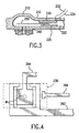
- FIGs. 2-4 an integrated device 200 according to another embodiment is shown.
- the integrated device 200 is shown as part of an analyte assay system that is similar to system 10' shown in FIG. 1, but with additional features.
- the integrated device 200 comprises a top layer 210, a bottom layer 220, and a sensor 230.
- the top layer 210 may be integral with the bottom layer 220.
- the top layer 210 has an optically transparent window portion 212.
- the sensor 230 is disposed between the top layer 210 and the bottom layer 220.
- a layer of photothermal material 240 is either applied to the tissue, or is formed on or integrally with the bottom layer 220. Electrode leads 232 connect to the sensor 230.
- Electrical connections to the integrated device 200 are preferably made with a position-invariant type of contact allowing for easy installation and removal of the integrated device 200 from a electrochemical sensor meter and/or optical energy source.
- FIG. 9 illustrates an embodiment that achieves this in a concentric configuration.
- An optional mesh layer 250 is provided in the integrated device to direct collected biological fluid to the sensor.
- the mesh layer 250 may be treated with a surfactant compound as explained above in conjunction with FIG. 1.
- a spacer element 225 is placed between the bottom layer 220 and the top layer 210.
- the spacer element 225 specifies the volume of fluid within the active area of the sensor 230. Specifically, if the aspect ratio of the height (H) of the spacer 225, to the width (W) of the roughly square or circular sensor 230 is less than about 0.1, then for all practical purposes the useable volume of fluid presented to the sensor 230 is defined by H*W*W.
- a surface tension driven or capillary feed channel provides an efficient and volumetrically compact method for conducting the flow of the sampled fluid from the micropore to the sensor 230.
- This channel may be optionally filled with a mesh layer 250 similar to that traditionally used in a number of existing glucose monitoring strips manufactured by both Boehringer-Mannheim and Medisense as well as others in the industry.
- both the capillary channel and the optional mesh layer 250 may be treated with a surfactant compound to enhance the fluid conductivity along this channel.
- Electrodes 262 and 264 there are two electrodes 262 and 264 that extend in and around the sensor 230, as is well known in the art.
- the electrode lead 232 connects to electrode 262 and electrode lead 234 connects to electrode 264.
- Electrodes 262 and 264 are the sense electrodes.
- Electrodes 268 and 269 shown best in FIG. 2 are the fill electrodes and are connected to the conductance monitor circuit 84 and to the fill monitor circuit 82.
- one of the fill electrodes 268 and 269 could be shared with one of the sense electrodes 262 and 264.
- a third electrode 266 were strategically placed to the right of electrode 262, and the fill direction was defined to be from the left, then when conductance was sensed between electrodes 262 and 266, this would indicate that the sensor was fully wetted and the reading process can be initiated via the sense electrodes 262 and 262.
- a conductance monitor circuit 84 and a fill monitor circuit 82 are incorporated as well as an electrochemical sense system, typically a common anode or common cathode design could be used as one leg of each of these circuits to reduce the total number of electrical traces necessary to be run into the integrated device.
- the conductance monitor circuit 84 is essentially the same as the fill monitor circuit 82, but the conductance monitor is responsive to the very first signs of a fluid sample in the integrated device. This can be used to control the poration process and shut it off in a closed loop fashion as soon as an active pore has been formed as determined by the ability of the pore to source fluid.
- the fill monitor circuit 82 is responsive to determining that the sensor 230 has been sufficiently wetted with a fluid sample in order to begin the measurement of the sensor 230 by the analyte processing circuit 80.
- the electrode leads 232 and 234 connect the sense electrodes 262 and 264 to the analyte processing circuit.
- a microprocessor control circuit 40' is provided, and is connected to the analyte processing circuit 80 and fill monitor circuit 82.
- the microprocessor control circuit 40' is programmed to control the interaction with the integrated device 200.
- the microprocessor control circuit 40' generates signals to display analyte measurements and other information on the display 50.
- the microprocessor control circuit 40' controls the application of optical energy and other parameters to the integrated device 200 to effect the microporation and harvesting process.
- a suitable error message might be displayed and the user prompted to reinitialize the system, install a new integrated device 200 and try again at a fresh site on the tissue surface.
- a temperature measurement may be obtained from the site and/or sensor in order to correct for temperature sensitivities in the measurements obtained by the sensor.
- the system 10' includes a laser control circuit 32, a laser analog circuit 34, a transducer control circuit 62 and a transducer analog circuit 64.
- both the digital control circuitry and analog output stages could be combined into a single circuit or even fabricated as a mixed mode application specific integrated circuit (ASIC).
- ASIC application specific integrated circuit
- the following discussions of the particular functions of each portion of the control and driver circuitry apply equally to either the discrete implementation, a partially integrated ASIC version or a wholly integrated ASIC version.
- the laser control circuit 32 is responsive to commands from the microprocessor control circuit 40' to generate analog signals that are processed by the laser analog circuit 34 to drive the optical source 30.
- the transducer control circuit 62 is responsive to commands from the microprocessor control circuit 40' to generate analog signals that are processed by the transducer analog circuit 64 to drive the sonic transducer 60.
- An interface assembly 90 supports the sonic transducer 60, beam former 70 and focusing lens 32.
- the interface assembly further comprises an alignment member 92 that mates with an alignment indentation or key 202 on the substrate layer 210 of the integrated device 200. This assures that the optical energy from the source 30 will be properly focused on the integrated device 200, and that sonic energy will be properly coupled through the integrated device 200 to the tissue.
- These alignment features also ensure that a proper reference is achieved between the micropore formed and the fluid sample collected, and further facilitates proper wetting of the sensor 230 inside the integrated device.
- the operation of the system 10' and integrated device 200 is as follows. Once the integrated device 200 is in position on the surface of the tissue, the microprocessor control circuit 40' activates the source 30.
- the source 30 may be a pulsed laser diode, and the microprocessor control circuit 40' will activate it within a predetermined energy range.
- the optical energy is focused onto the tissue surface through the substrate top layer 210 and onto the photothermal material 240.
- the photothermal material 240 is responsive to the optical energy to transfer heat to the surface of the tissue to form one or more micropores therein. As shown in FIG. 4, the one or more micropores M are shown as being made around the periphery or in the middle of the sensor 230.
- the microprocessor 40' may also control the application of sonic energy.
- the application of optical energy and/or sonic energy continues until the conductance monitor circuit 84 senses the presence of some amount of biological fluid in the integrated device 200.
- the optical source 30 is deactivated.
- the microprocessor 200 may continue the delivery of sonic energy until the fill monitor circuit 82 detects that the integrated device 200 has collected sufficient biological fluid to make an accurate assay measurement, or until some maximum time period expires. Once this occurs, the biological fluid will contact the sensor 230 and an analyte measurement can be made by the analyte measurement circuit 80, which information is coupled to the microprocessor control circuit 40' for display on the display 50.
- the optional wicking mesh layer 250 (optionally treated with a surfactant compound) will assist in directing the biological fluid to the sensor.
- Another way to direct the biological fluid to the sensor 230 is by applying a mechanical force downward on the integrated device 200, as shown in FIG. 5.
- a cam or roller mechanism 280 is applied to the top of the integrated device to form an indent in the integrated device 200 along the top of the layer forming the upper boundary of a capillary channel between the top layer 210 and bottom layer 220.
- the cam mechanism 280 is applied in a "squeegee" type action, moving the fluid sample down this channel to the sensor 230. This allows a positive, rapid delivery of fluid to the sensor with a minimum amount of fluid sample.
- the application of negative pressure may be used to harvest the biological fluid into the integrated device 200. It has been shown in clinical studies that a small level of pressure reduction, even as little as 1 ⁇ 4 ATM, can produce a steady outflow of interstitial fluid from the micropores.
- the flux rate under vacuum appears to obey an essentially linear relationship with pressure, as the pressure is reduced to 1 ATM, however, optimal values seem to be more in the 1 ⁇ 4 to 3 ⁇ 4 ATM range due to effects on the surrounding tissue and potential heating of the fluid sample.
- Integrated device 300 has a different configuration than integrated devices 100 and 200 described above.
- Integrated device 300 has a trapezoidal cross-section and comprises an optically transparent top membrane 310 and a bottom layer 320.
- a removable membrane 322 may be provided that covers the bottom layer 320 until the integrated device 300 is to be positioned on tissue for use. At least a portion of the bottom layer 320 may be treated with a photothermal material 324.
- the membrane 322 is not removable and comprises a thin film of an optically absorbent photothermal material designed to vaporize during the microporation process.
- the tissue itself may be treated with photothermal material before the integrated device 300 is positioned on the tissue.
- the bottom layer 320 would be made of optically transparent material that vaporizes in the presence of the thermal energy created during poration, or this portion of the bottom layer may be removable just prior to applying the integrated device to the pre-treated area of the tissue surface.
- the bottom layer may be treated with an adhesive so that the integrated device 300 is secured to the surface of the tissue.
- the adhesive serves several functions. First, it preserves proper registration of the openings created in the integrated device with the openings created in the tissue to collect the fluid sample. Second, it allows for attachment of the device to the tissue so that an individual can operate it hands-free. Third, the adhesive will form a vacuum seal between the bottom layer of the integrated device and the tissue surface, thereby preventing biological fluid from passing beneath the integrated device uncollected. The vacuum seal also facilitates the application of negative pressure to the harvesting site.
- the integrated device 300 comprises a chamber 330 to collect biological fluid in the center portion of the device.
- the chamber 330 is cylindrical in shape as shown in FIGs. 6 and 7.
- a sensor 340 is disposed on at least a portion of the inner wall of the chamber 340.
- FIGs. 6 and 7 show a cylindrical chamber, any other shape convenient to a particular application may be used for the chamber.
- a flat walled shape such as a triangle, square or pentagon, in which the active sensor pad is placed on one of these walls.
- FIG. 7 a typical electrical wiring diagram is shown to support most electrochemical sensors used to date.
- a reference electrode 352 and a sense electrode 354 are provided that connect to the sensor 340.
- the integrated device 300 may include additional electrodes to support the "fill" and "conductance” features described above, or even if the electrochemical assay system used requires additional electrical interfaces to function optimally.
- the reference electrode is useful for many electrochemical assays to provide a self calibrating feature wherein the actual assay reaction can be read as more of a difference measurement across a balanced impedance bridge.
- the sense electrode could be the assay output, which is similar to the "fill” or a "conductance” signal described above. Although dedicated anode and cathode terminals are shown, it is common practice to use one or the other of these as the sense electrode and share the other one with the reference electrode.
- the electrode configuration shown in FIGs. 6 and 7 indicates that the integrated device 300 supports the use of many of electrode configurations.
- an acoustic lens 360 Disposed around the chamber 330 between the top membrane 310 and the bottom layer 320 is an acoustic lens 360 formed of material suitable for coupling sonic energy.
- the acoustic lens 360 is formed of silicone material molded into a shape suitable for being disposed inside the integrated device 330.
- a lens material of a suitable durometer value will ensure sufficient sonic coupling to the tissue beneath, and also achieves pneumatic sealing if suction or negative pressure is used in the harvesting process.
- Sonic transducers 370 are positioned on the lateral surfaces of the integrated device to deliver sonic energy to the tissue through the acoustic lens 360. In order to facilitate alignment of the integrated device 300 with the remaining components of an assay system (similar to that shown in FIGs.
- the integrated device 300 may be contained within a housing 390 that includes an optical focusing lens 392 molded therein to focus optical energy from source 30 onto the photothermal material 324.
- the operation of the integrated device 300 is similar to the descriptions above of integrated devices 100 and 200. However, the biological fluid harvested by the integrated device 300 is collected in the chamber 330 and contacts the sensor 340 placed on the side walls of the chamber 330, rather than a planar sensor shown in the previous embodiments.
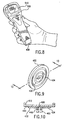
- the integrated device 400 is designed for use with a hand-held unit 500 that processes assay measurements obtained by the integrated device 400 and displays the measurements on a display 510.
- the integrated device 400 is a disc-shaped member that supports the components for fluid harvesting and assay measurement.
- the integrated device 400 comprises a substrate member 410 configured in a circular shape and having flanges 412 that snap fit onto a bottom portion of the hand-held unit 500.
- a sensor 420 is positioned at a central location on one surface of the integrated device 400.
- First and second electrodes (anode and cathode) 432 and 434 extend concentrically on the bottom surface of the substrate 410 and make connection from opposite sides to the sensor 420.
- An optional mesh 440 may be disposed over the sensor 420.
- the mesh 440 may be treated with a suitable surfactant compound described above.
- a layer of photothermal material 450 is disposed over the opening placed on the bottom of the integrated device to allow the harvested fluid to wet the sensor 420, or the tissue itself is treated with photothermal material 450.
- the integrated device 400 is operated by attachment to the hand-held unit 500 and positioned on the surface of the tissue to be microporated.
- the hand-held unit contains the optical source to focus optical energy onto the photothermal layer 450 to form one or more micropores in the tissue.
- Biological fluid from the tissue makes contact with the sensor 420 (preferably with the assistance of the mesh layer 440).
- the hand-held unit 500 includes processing circuitry that electrically couples to the electrodes 432 and 434 to obtain an assay measurement from the sensor 420.
- the hand-held unit 500 is activated by engaging the integrated device 400 against the tissue surface with sufficient pressure together with pressing an activation button on the hand-held unit 500.
- the poration process is based on the application of optical energy to an absorber target which in turn heats up sufficiently to conductively deliver enough thermal energy to the skin to ultimately cause the desired thermally induced microporation.
- An alternative approach to delivering this heat energy to the poration sites involves the placement of an electrically heated probe directly at the poration site. The temperature of the electrically heated probe is modulated as needed to effect the microporation process.
- FIGs. 11 and 12 A schematic representation of an integrated device 600 employing an electrically heated probe (heat conducting element) is shown in FIGs. 11 and 12.
- the integrated device 600 comprises a layer 610, an optional mesh layer 620, and a sensor 630, which in this example, is a colorimetric sensor. It should be understood, however, that this same concept could easily be modified to employ the electrochemical biosensor.
- many of the aspects of the assay/fluid management systems of the device are optional, such as the use of the mesh layer 620, surfactant treated portions of the fluid management chamber, optically transparent windows in the layers to allow the reading of a colorimetric assay, methods for applying sonic energy, vacuum or negative pressure, mechanical manipulation, etc.
- At least one electrically heated probe 640 there is provided at least one electrically heated probe 640.
- the types of electrically heated probes that are suitable are disclosed in the aforementioned published PCT application, WO 97/07734 .
- the electrically heated probe 640 comprises an electrically conductive element or wire 642 provided on the bottom surface of the layer 12.
- Three electrically conductive elements 640 are shown as an example, though any number of them may be provided.
- An electrical conductor 644 extends the length of the layer 610 and terminates in a "T" that extends laterally across one end of the layer 610.
- Three other electrical conductors, 650, 652 and 654 extend the length of the layer 610 and terminate at a plurality of points near the termination of conductor 644.
- the three elements 640 are connected to conductor 642 and respectively to conductors 650, 652 and 654.
- the electrical conductors 644, 650, 652 and 654 required to activate the elements 640 can be made through the same type of connectors used to interface to the electrical output electrochemical biosensor.
- Each poration element 640 can be activated individually through the appropriate selection and energization of the conductors 650, 652 and 654. It may be advantageous to excite all poration elements 640 simultaneously, thereby enabling either a series or parallel wiring design, reducing the number of interconnections to the disposable poration system and facilitating a more rapid poration process. If only one element 640 is provided, then at least two conductors are provided for supplying electric current through the heatable element. One of these conductors may be shared with the assay sensor/fill/conductance circuitry as a common anode or cathode, thereby necessitating the additional of only one electrical connection to the integrated device.
- thermal poration elements could be installed on a conventionally manufactured assay strip as an additional post-processing step.
- the conductors 644, 650, 652 and 654 are embedded within the tissue-contacting layer so as not to be exposed on the bottom surface thereof, but to enable sufficient electrical connection to the one or more heated elements 640.
- Each of the elements 640 functions as a solid thermal probe and is electrically heated so that the temperature of the tissue, if skin, is raised to a temperature greater than 123 C.
- each element comprises a 100 to 500 micron long 50 micron diameter tungsten wire. These tungsten wires are typically laid flat against some form of backing (such as the tissue-contacting layer 12) which naturally limits the depth of penetration of the wire into the tissue (by virtue of the diameter of the wire).
- the temperature of the wire may be modulated according to the techniques disclosed in the aforementioned PCT publication.
- the inlet ports to the fluid management chamber of the integrated device 600 may be small holes in the tissue-contacting layer across which the wires 640 extend.
- a meltable or vaporizable membrane is placed above the wires 640. When energized, the wires melt a hole in this membrane, creating an inlet port to the fluid management chamber at each location of the wires 640.
- a system can be designed wherein the electrically heated poration elements 640 are contained in a separate component or device, which may be reusable. These elements would be replaced when it is detected that they are worn sufficiently to require replacement, or routinely, such as on a weekly basis, similar to a diabetic subject's replacement of a lancet tip in a fingertip lancing blood-drawing device.
- the type of optical energy source may be any of those described in the aforementioned PCT application WO 97/07734 .
- the types of substances used for the photothermal material are disclosed in PCT publication WO 97/07734 and the aforementioned U.S. provisional application.
- the sensor used to react with the harvested biological fluid and measure a characteristic of the fluid may be an electrochemical biosensor comprised of a layer or layers of chemicals capable of reacting with an analyte in a collected biological fluid to produce a measurable electrical response (as specifically shown in some of the foregoing embodiments).
- U.S. Patent Nos. 4,545,382 and 4,711,245 describe detecting layers capable of generating a measurable electrical signal in response to glucose in blood. The electrical signals are measured by a measuring circuit (such as the one shown in FIGs. 1 and 2 at reference numerals 20 and 80, respectively) obtained by electrical leads connected to electrodes in or around the active area of the biosensor.
- the senor may be a colorimeter sensor, a fluorescent intensity-based sensor or a fluorescent life-time based sensor.
- electrochemical biosensors that are suitable for use in the integrated device are those manufactured by Medisense, Boehringer Manheim, KDK, etc.
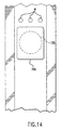
- the integrated device shown in FIG. 13 may be any one of those described in the foregoing embodiments.
- the sensor to be optically read is shown at reference numeral 700.
- the sensor 700 is held in sufficient registration to enable the optical field of view 730 of an optical meter 720 to be placed nominally in the center of the region of the colorimetric sensor wetted by biological fluid.
- the field of view of the optical meter 720 is optically cropped such that it conservatively under fills the area known to be wetted by the fluid sample.
- the colorimetric sensor 700 is treated with a probe fluorophore.
- a reaction between a probe fluorophore and the selected analyte produces a predictable change in the fluorescent intensity of the probe molecules when excited with a particular optical wavelength such that the subsequent fluorescence is detected at a selected longer wavelength.
- the fluorescent probe is selected such that it can emit in two different wavelength bands, wherein the intensity of energy in only one of the bands is predictably modified by the varying concentration of the selected analyte.
- a ratiometric processing of the two different fluorescent intensities can be employed, thereby simplifying the calibration of the reading and allows for self-adjustment for different amounts or areas of the colorimetric sensor wetted with the biological fluid.
- the fluorescent interrogation field of view may be defined by the intersection of the incident excitation light and the look field of the fluorescent receive channels.
- the assay technique used in conjunction with the integrated device may be based on a fluorescent lifetime based assay technology.
- a reaction between a probe fluorophore, with which the colorimetric sensor 700 is treated, and the selected analyte produces a predictable change in the fluorescent lifetime of the probe molecules when excited with a particular wavelength.
- the subsequent fluorescent lifetime is detected at a selected longer wavelength.
- the detection of the fluorescent lifetime may be accomplished by either measuring directly the decay of the fluorescence in response to a known pulse shape of excitation light, or by measuring the phase shift and modulation depth of the fluorescent signal in response to the excitation of the sensor by a periodic modulated light source at the appropriate excitation wavelength.
- the integrated device according to the present invention may be used in a continuous monitoring system.
- the system could be integrated with other devices, including an insulin pump.
- the continuous monitoring system would provide a real-time feedback to achieve a closed loop artificial pancreas system without requiring an implant.
- the integrated device would be connected to a "smart" insulin pump that would respond initiate a glucose measurement (or one would be initiated on demand by the patient) and would administer an appropriate amount of insulin depending on the glucose measurement obtained.
- each has a fluid management chamber designed to direct the biological fluid collected to the sensor.
- the surfaces of the fluid management chamber may be selectively treated with chemical substances, such as a wicking agent, or a surfactant to induce the migration of fluid in a particular direction, i.e., to the sensor.
- chemical substances such as a wicking agent, or a surfactant to induce the migration of fluid in a particular direction, i.e., to the sensor.
- certain portions of the surfaces of the layers in the fluid management chamber, such as the tissue-contacting layer may be treated with a hydrophobic compounds or substances to direct the biological fluid away from a selected region or regions where it is not desired for the biological fluid to migrate and to direct the biological fluid toward the sensor.
- waste fluid which would be created as a fresh fluid sample where harvested and moved into the sensor area.
- One solution for this waste fluid is to merely expand the overflow region provided in many of the current assay strip designs discussed and referenced above, to a size large enough to act as a fluid sink for this used fluid sample. This expanded overflow region also addresses the desire to keep these fluid samples contained within the integrated device element to maintain control over the ultimate disposal of the biological sample such that it can be handled with appropriate caution.
- a system can be built which uses very small samples of biological fluid to obtain an accurate assay of a selected analyte.
- Tests have been conducted on commercially available systems using glucose sensing amperometric biosensors that incorporated all of these features and it was found that the glucose concentration in a sample of biological fluid smaller than 1/3 of a microliter could be quantified, by modifying commercially available glucose test strips.
- One of the additional advantages gained by using interstitial fluid as the fluid sample for the assay system is the almost total lack of red blood cells in the sample.
- a typical sample size of 3 to 10 microliters is normally required for a blood based glucose monitoring disposable assay strip design whereas by utilizing the ability to place an unfiltered interstitial fluid sample directly on the active reagent treated portion of an assay system, it has been demonstrated that quantitative readings of a selected analyte can be obtained with fluid samples as small as 1/3 ⁇ L of interstitial fluid using modified conventional disposable assay strip technologies.
- Another example of a closed lop application of the integrated device is to collect and monitor the levels of a particular drug in the blood stream or other fluid, wherein it is desired to maintain the drug level within a defined serum concentration window.
- an infusion pump would be controlled to respond, taking into account the total system bandwidth, and deliver small pulses of the therapeutic drug into the subject until the desired set point level had been reached, wherein the pump would then be put on standby until the drug levels dropped below the set point, thus triggering another pulse of the drug.
- Bandwidth in this context refers to the sum of all delays associates with the infusion of the drug, distribution within the body, diffusion into the fluid reservoirs from which the integrated device collects its fluid sample, and any additional delays in the sampling and processing involved before a change in the reported assay value would occur.
- drugs commonly prescribed could benefit from this sort of tight control over dosage levels such as many of the anti-seizure drugs, pain medications, chemotherapies, etc.
- an additional control input could be given to the user allowing them to ask for an additional dose in an on-demand fashion to deal with breakthrough pain, and use the closed loop monitoring feature as a final safety to ensure that no toxic overdose levels would occur.
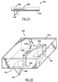
- an integrated device 1000 according to still another embodiment is shown.
- the integrated device 1000 is similar in many respects to the previous embodiments, but includes one or more mechanical porating elements.
- the integrated device 1000 comprises a substrate layer 1010 and a plurality of mechanical porating elements 1030 protruding from the bottom of the substrate layer 1010.
- the specific structure and arrangement of the mechanical porating elements are disclosed in commonly assigned published PCT application WO 98/00193 , referred to above.
- the integrated device 1000 further comprises an assay sensor 1020 disposed above the mechanical porating elements 1030.
- the assay sensor 1020 is any of the sensors described above.
- An optional additional top layer 1040 may be provided to seal the top surface of the integrated device. If the assay sensor 1020 is a type that is optically read, then the top layer 1040 is optically transparent.
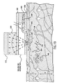
- the mechanical porating elements 1030 are puncturing elements very small in size (10 to 50 microns), and are spaced apart from each other. With reference to FIG. 22, each porating element 1030 comprises a sharp point or edge 1032 for puncturing the tissue surface. Depending on the desired depth of the micropores to be created, the height of the porating element 1030 will vary.
- the porating elements 1030 may be pyramid or wedge shaped, which is easily created by microfabrication techniques, such as microlithography. Other shapes for the porating elements 1030 may be suitable, such as that of micro-lancets or micro-needles.
- the holes 1050 are of suitable dimension to permit biological fluid, such as blood or interstitial fluid, to move by capillary action from the lower side 1012 of the substrate layer 1010 to the upper side 1014.
- the holes 1050 may be interconnected with channels 1060 that are formed on the upper side 1014, and the channels 1060 may intersect at a reservoir 1070.
- the assay sensor 1020 (not shown in FIG. 22 for simplicity) is then positioned on top of, partially overlapping, or adjacent the reservoir 170, so that it is sufficiently wetted with the biological fluid to make a suitable measurement.
- the integrated device 1000 may include surface tension enhancements, such as a wicking mesh (surfactant treated or not) and surfactant treatment of the holes 1050 and channels 1060.
- the wicking mesh would be positioned to overlie the reservoir 1070 and thereby enhance the transport of the biological fluid to the assay sensor 1020.
- the integrated device 1000 may be modified to include any of the enhancements discussed below.
- FIGs. 15 and 16 illustrate the use of a pneumatic seal together with any one of the integrated devices described above.
- a sealing means in the form of a sealing assembly 800 is provided which comprises a perimeter base 802 that fits around the integrated device (100, 200, 300, 400, 600, 1000), and a top layer 804 that is sealed to the perimeter base 802, and extends above the integrated device.
- the sealing assembly 800 pneumatically seals around the integrated device to the surface of the tissue. If the integrated device is of the type that requires exposure to optical energy, the top layer 804 is made of optically transparent material.
- the perimeter base 802 seals to the tissue surface around the integrated device, such as by an adhesive, or a tacky silicone, rubber or plastic element.
- a sealed chamber 806 is formed in the space between the integrated device and the top layer 804.
- a vacuum port 808 is provided in the top layer 804 for connection to a means for supplying negative pressure, such as a pump 820 or other source of negative pressure, such as a syringe, a diaphragm or some portion of the chamber which can be flexed outward to increase the volume of the chamber and thereby reduce the pressure within the chamber or the like.
- a means for supplying negative pressure such as a pump 820 or other source of negative pressure, such as a syringe, a diaphragm or some portion of the chamber which can be flexed outward to increase the volume of the chamber and thereby reduce the pressure within the chamber or the like.
- a sealed electrical connector 810 in the top layer 804.
- the sealed chamber 106 is formed against the surface of the tissue, such as the skin, over the poration site(s).
- the pressure in the chamber 106 can be reduced to provide a positive pressure gradient from within the body towards the sealed chamber 106 through the micropores to induce the biological fluid to exit the body and enter the integrated device 10 more rapidly.
- the evaporative losses of the biological fluid can be minimized. Once the humidity inside the chamber 806 reaches a saturation point, no more evaporative losses can occur. These evaporative losses can further be reduced by managing the biological fluid in a manner wherein the exposed surface area of the biological fluid pool that has exited the tissue is kept small. When induced to enter the device, the biological fluid is constrained on all sides other than the port(s) in the fluid management chamber at the microporated site.
- the side layer or wall of the fluid management chamber opposite these ports could be constructed with one or more very small opening(s) to create a vent allowing the biological fluid to fully fill the fluid management chamber, yet minimize the exposed surface of the biological fluid when the assay area is full, thereby reducing evaporation.
- the reduction of evaporative losses is more significant when using a vacuum-induced harvesting process because the rarefied atmosphere will accelerate any evaporation process.
- evaporative losses can consistently be kept under 5% over a 45 second harvesting cycle.
- a large chamber and an exposed bead of biological fluid on the surface of the skin can allow up to 30% of the biological fluid to evaporate during this same 45 second interval, under the same temperature conditions.
- An additional feature of pneumatically sealing the integrated device is that by virtue of its contact with the tissue, these portions of the integrated assay system maintain the mechanical alignment of the micropore(s) in the tissue with the inlet ports of the integrated device.
- FIGs. 17 and 18 illustrate the use of a mechanical system to apply positive pressure to the integrated device.
- a mechanical element 850 is provided, having a small opening 852, 2 mm to 4 mm in diameter.
- the mechanical element 850 permits the integrated device to slide between two opposing surfaces and contains the integrated device. Applying force to the mechanical element 850 presses the integrated device onto the skin at the poration site and thus creates a positive pressure gradient in the biological fluid harvested from the tissue TS, i.e., the skin, forcing it towards the micropores where it can exit the tissue and enter the inlet port(s) of the fluid management chamber of the integrated device (100, 200, 300, 400, 600, 1000).
- the mechanical device 850 may be optically clear on its top portion to allow for optical thermal ablation and optical reading of the photometric sensor in that form of the integrated device.
- the application of mechanically induced pressure may be continuous, modulated as in a sine or triangle wave, or pulsed.
- the rate and modulation pattern may be optimized to take advantage of the fluidic properties of the skin tissues such as the local permeabilities, and the refill or recovery rates of the tissue once some portion of the biological fluid has been pressed out of it.
- Clinical experiments have demonstrated that applying a few pounds per square inch of pressure to the skin with a flat plate having a 2 mm to 4 mm diameter hole in it surrounding the micropore(s) rapidly forces biological fluid to exit the pores and pool on the surface of the skin.
- the use of the mechanical device may be combined with vacuum to provide an additional biological fluid forcing function, and to possibly assist in the fluid management of the biological fluid as it exits the body.
- a further benefit of applying firm pressure to the system during the thermal poration process is that this pressure helps ensure a good thermal connection between the heat probe created by the optically heated absorber targets and the skin to be porated.
- the input ports or channels to the assay system be in physical registration or alignment with the micropores on the skin to ensure an efficient transfer of fluid from the micropores to the assay strip.
- Registration and alignment can be achieved by employing an adhesive or tacky silicone product to temporarily attach the integrated device.
- registration and alignment can be accomplished by installing the assay strip component within a translation system which, when activated, brings the input ports or channels of the assay strip into close enough proximity to the biological fluid exiting the micropores to cause the directed flow of this biological fluid into the assay strip.
- This sort of translation can be achieved in a number of ways such as, but not limited to, a small servo motor activated by a controller to move the assay strip into position at the appropriate time; a pneumatically positioned system driven by the same vacuum source described in conjunction with FIGs. 15 and 16; or a system design wherein the flexure of the skin itself under either the vacuum or pressure as described above brings the biological fluid on the surface of the skin into contact with the assay strip.
- An additional advantage of the translation system in the fluid management portion of the integrated microporation, harvesting, assay system is that it can be designed to supply the entire required fluid sample in a bolus delivery to the assay system, rather than trickling it over some longer period of time. In many cases a bolus delivery of sample fluid enables a more accurate assay to be conducted using standard disposable assay strip design concepts.
- a typical sample size of 3 to 10 microliters is normally required for a blood based glucose monitoring disposable assay strip design whereas by utilizing the ability to place an unfiltered interstitial fluid sample directly on the active reagent treated portion of an assay system, it has been demonstrated that quantitative readings of a selected analyte can be obtained with fluid samples as small as 1/3 ⁇ L of interstitial fluid using modified conventional disposable assay strip technologies.
- the integrated device can be used in conjunction with a means for coupling sonic energy from a transducer into the system and optionally into the tissues upon which the integrated system is disposed.
- a means for coupling sonic energy from a transducer into the system and optionally into the tissues upon which the integrated system is disposed In particular, experiments have shown that sonic energy in the range of 5 kHz to 30 MHz can be useful to enhance the outflux of biological fluid from a microporated area of skin.
- the literature on the use of sonic energy supports the extension of the useable frequencies as high as 500 MHz.
- the permeation enhancing effect of sonic energy is due to several different mechanisms in the tissue, including but not limited to, the acoustic streaming induced in the fluids within the skin tissues, the directable effects of the sonic radiation pressure which can act directly to push the fluid is a desired direction, the reduction in the viscosity of the fluid itself, the modification of the surface tension effects both within the tissues and at the surface of the micropore, the local heating possible from the absorption of the sonic energy and the body's natural edemic response to this, the opening of microscopic temporary channels in the various membranes and layers within the tissue such as the capillary and vessel walls, the effect on these tissue structures due to cavitation achieved with selected frequencies and intensities of sonic energy, and the simple physical shaking of the system possible with various pulsed and modulated patterns of sonic energy, and the like.
- a sonic energy source When incorporating a sonic energy source into a system such as this, it is important to consider the acoustic impedance of the various layers through which the sound waves travel, and the matching of the acoustic impedance at the interfaces of the various layers.
- a gel is frequently used to facilitate the coupling of the sonic energy into the tissue and this approach could be used to mate the bottom surface of the integrated device element to the surface of the tissue, such as skin.
- An alternative solution to the coupling issue that eliminates the need for a coupling gel is to use an appropriately designed gasket type of material, such as a silicone or hydrogel to form the sonic connection.
- tacky or adhesive elements are useful to both seal a fluid management chamber and maintain registration between the micropores and the inlet port of the assay system. These elements are also useful as efficient acoustic coupling agents.
- the schematic representation in FIG. 19 shows an integrated device (100, 200, 300. 400, 600. 1000) having a compliant layer 900 placed on the top to form an efficient coupling for sonic energy.
- the sonic energy is generated by sonic energy generation means, such as a piezo-electric transducer 910.
- a sonic lens element 920 is placed between the piezo-electric transducer 910 and the compliant layer 900.
- a coupling gasket 930 may also be provided to pneumatically seal the integrated device to the surface of the tissue (with optional application of suction) and to assist in the acoustic coupling of the sonic energy.
- the acoustic waves can be optimized to have any of several recognized actions and effects on the performance of the harvesting and analysis of biological fluid, or delivery of bio-active agents.
- the sonic energy can be propagated through the integrated device, through the coupling gasket 930, to the tissue (such as skin), wherein SC denotes the stratum corneum, E denotes the epidermis and D denotes the dermis.
- the direct effects of the sonic energy include local warming of the tissue through the direct absorption of the sonic energy. This is shown at reference numeral 940.
- an acoustic streaming effect can be achieved within the tissue, accelerating the fluidic movement between cells and within cells and vessels. This is shown at reference numeral 942.
- the amount of increase in the local velocity of the fluid has been shown to be more than one order of magnitude using visible tracers in in vivo real-time video microscopy experiments.
- cavitation bubbles at reference numeral 944 when the frequency and intensity and possible modulation thereof are selected appropriately, a cavitation effect shown by cavitation bubbles at reference numeral 944, is achieved which can have substantial secondary effects on the tissue properties due to possible microscopic shearing of some tissue structures, the transitory opening up of micro-porous sites in various membranes such as the capillary walls CW within the tissue, and other effects due to the shock waves, shown at reference numeral 946, created upon the collapse of the cavitation bubble.
- the presence of the acoustic vibrations within the fluid management chamber of the integrated device itself can also be used to enhance the motion of the fluid. These effects can be due to a directed radiation pressure gradient shown at reference numeral 948 which can be created by proper alignment and focusing of the sonic energy, the enhancement of capillary transport action shown at reference numeral 950 by the acoustic energy, the active out-gassing of dissolved gas in the fluid which can help to eliminate error causing bubbles in the active assay area of the system, and the localized and chaotic micro-fluidic vortices shown at reference numeral 950 created within the fluid management chamber which can be used to reduce the required assay reaction time by eliminating the dependency on passive diffusion effects and thereby evenly distribute the reactive process within the sample.
- the activation of the sonic energy source can be selectively controlled to work in a coordinated fashion with the other components of the system, even to the point of operating with significantly different parameters during different portions of the poration, harvesting, assay process.
- a sequence of sonic energy use is:
- FIG. 19 Essentially all of the same functional modalities described in conjunction with FIG. 19 can also be realized with an alternative configuration wherein a remotely placed sonic source is used to direct the acoustic energy towards the desired portion of the assay element of the integrated device by beaming it through a fold of intervening flesh.
- a clamp assembly 960 is provided to pinch a fold of tissue, such as skin between a transducer assembly.
- the transducer assembly comprises an acoustic transducer 962, a focusing element 964, and a coupling layer 966.
- the integrated device (100, 200, 300, 400 and 600) is at an opposite side of the pinch of skin.
- the dimensions of the clamp assembly 960 are such that when the tensioning device 968 pulls the two clamp halves together, they hit a hard stop and the spacing from the face of the transducer assembly and the inlet port of the fluid management chamber of the integrated device is positioned at an optimal position in ⁇ x, y, and z ⁇ coordinates to coincide with the sonic energy fields as desired. For example, FIG.
- the focal point of the sonic field is roughly coincident with the inlet port of the assay chamber, which may be one selected mode of operation. However, by shifting the frequency of the sound waves, this focal point can be moved in and out from the face of the transducer.
- the coupling losses at this interface can be reduced and/or controlled within a design specification.
- the initial deflection into the inter-clamp space can be accomplished by placing the entire assembly within a suction system, such as that shown in FIGs. 15 and 16, which pulls the flesh into the space, and as the vacuum increases, provides the clamping force to pull the two halves of the clamp assembly together to the stops. Similarly this could be accomplished via mechanically feeding a pinch of skin into the space and then letting the clamp grab the tissue.
- the present invention is directed to an integrated poration harvesting and analysis device, comprising a first layer having a porating element disposed thereon, the porating element forming at least one opening in the tissue; a sensor positioned in fluid communication with the at least one opening in the tissue, the sensor being responsive to a biological fluid collected from the tissue to provide an indication of a characteristic of the biological fluid.
- the present invention is directed to an integrated fluid harvesting and analyis device comprising a first layer for positioning in contact with tissue and through which poration of tissue is achieved such that at least one opening is formed in the first layer and at least one opening is formed in the tissue; a sensor positioned in fluid communication with the at least one opening of the first layer, the sensor being responsive to a biological fluid collected from the tissue to provide an indication of a characteristic of the biological fluid.
- a quantity of photothermal material is disposed on a portion of the first layer, which is heated by optical energy to form the micropore (opening) in the tissue, and thereby create the opening in the first layer.
- a counterpart method for harvesting biological fluid from tissue and analyzing the biological fluid comprising steps of placing a layer in contact with a surface of tissue; forming at least one hole in the tissue; collecting biological fluid from the tissue through at least one opening in the layer; and wetting a sensor that is positioned in fluid communication with the at least one opening in the layer with biological fluid to measure a characteristic of the biological fluid.
- the means to form the opening may be a mechanical element (lancet, needle, etc.), an electrically heated poration element, an optically heated poration element, etc.
- the opening in the tissue may be formed adjacent to an edge of the layer, whereby biological fluid enters the layer through a capillary feed channel formed between the top and bottom layers of the device, as described above.
Landscapes
- Health & Medical Sciences (AREA)
- Life Sciences & Earth Sciences (AREA)
- Physics & Mathematics (AREA)
- Animal Behavior & Ethology (AREA)
- Veterinary Medicine (AREA)
- Public Health (AREA)
- Biophysics (AREA)
- General Health & Medical Sciences (AREA)
- Engineering & Computer Science (AREA)
- Molecular Biology (AREA)
- Heart & Thoracic Surgery (AREA)
- Medical Informatics (AREA)
- Surgery (AREA)
- Biomedical Technology (AREA)
- Pathology (AREA)
- Hematology (AREA)
- Dermatology (AREA)
- Optics & Photonics (AREA)
- Pain & Pain Management (AREA)
- Manufacturing & Machinery (AREA)
- Spectroscopy & Molecular Physics (AREA)
- Chemical & Material Sciences (AREA)
- Medicinal Chemistry (AREA)
- Pharmacology & Pharmacy (AREA)
- Epidemiology (AREA)
- Emergency Medicine (AREA)
- Measurement Of The Respiration, Hearing Ability, Form, And Blood Characteristics Of Living Organisms (AREA)
- Investigating Or Analysing Biological Materials (AREA)
- Sampling And Sample Adjustment (AREA)
- Medicines That Contain Protein Lipid Enzymes And Other Medicines (AREA)
- Media Introduction/Drainage Providing Device (AREA)
- Investigating Or Analysing Materials By The Use Of Chemical Reactions (AREA)
- Manufacture Of Macromolecular Shaped Articles (AREA)
- Materials For Medical Uses (AREA)
- Peptides Or Proteins (AREA)
- Analysing Materials By The Use Of Radiation (AREA)
- Diaphragms For Electromechanical Transducers (AREA)
- Confectionery (AREA)
Abstract
Description
- This invention relates to an integrated device for the creation of micropores or small holes or perforations in tissue, the collecting a biological fluid from the tissue through the small holes, and monitoring or analyzing a characteristic of the biological fluid, such as for the concentration of an analyte.
- The prevalence of diabetes has been increasing markedly in the world. At this time, diagnosed diabetics represent approximately 3% of the population of the United States. It is believed that the total actual number of diabetics in the United States is much higher. Diabetes can lead to numerous complications, such as, for example, retinopathy, nephropathy, and neuropathy.
- The most important factor for reducing diabetes-associated complications is the maintenance of an appropriate level of glucose in the bloodstream. Proper maintenance of the level of glucose in the bloodstream may prevent and even reverse many of the effects of diabetes.
- Traditional glucose monitoring devices operate on the principle of taking blood from an individual by a variety of methods, such as by needle or lancet. This is a multiple step process. First, a needle or lancet is used to make a hole in the individual's skin deep enough to obtain blood. Next, the individual applies a drop of blood to a strip which contains chemistry that interacts with the blood. Finally, the strip is inserted into a blood-glucose meter for measurement of glucose concentration based on a change in reflectance of the strip.
- These traditional glucose monitoring systems require that an individual have separately available a needle or lancet for extracting blood, separately available strips carrying blood chemistry for creating a chemical reaction with respect to the glucose in the blood stream and changing color, and a blood-glucose meter for reading the change in color indicating the level of glucose in the bloodstream. The level of blood glucose, when measured by a glucose meter, is read from a strip carrying the blood chemistry through a well-known process.
- There are other technologies being developed to provide an alternative to the conventional blood glucose monitoring procedures. One such technology involves measuring the level of glucose in interstitial fluid. In order to obtain samples of interstitial fluid, the barrier function of the stratum corneum must be overcome.
-
Published PCT application WO 9707734 - Another technique for removing the stratum corneum is by direct absorption of optical energy. See, for example,
U.S. Patent No. 4,775,361 to Jacques et al. - In sum, there are several ways of making small holes in the tissue including breaching the tissue mechanically with a needle or lancet, removing layers of tissue by thermal ablation techniques described above, or by the direct absorption of optical energy.
- There is room for improving glucose monitoring technologies. In particular, it is desirable to integrate several functions of the glucose monitoring procedure into a single device. Preferably, this device would facilitate the harvesting of a biological fluid, such as interstitial fluid, by making one or more small holes in the tissue, and the analysis of the biological fluid to determine a measure of a characteristic of the biological fluid, such as glucose level.
-
US Patent 5,458,140 discloses a method of enhancing the permeability of the skin or mucosa to an analyte so that such can be used for diagnosis purposes. - Briefly, the present invention is directed to an integrated device for harvesting biological fluid, such as interstitial fluid or blood, from tissue and analyzing the biological fluid. According to the present invention there is provided an integrated fluid harvesting and analysis device as claimed in claim 1, Several embodiments of an integrated device are disclosed. It is submitted that all disclosures provided hereinafter, which do not fall within the scope of the device claimed in claim , are provided for information purposes only and are not intended to extend the scope of protection afforded to the present invention.
-
- FIG. 1 is a comprehensive diagram of an analyte assay system including an integrated device according to one embodiment of the present invention.
- FIG. 2 is a comprehensive diagram of an analyte assay system including an integrated device according to another embodiment of the present invention.
- FIG. 3 is a partial cross-sectional view of the integrated device according to the first embodiment showing how biological fluid is collected and delivered to an assay pad.
- FIG. 4 is a top view showing the arrangement of the sense electrodes and sensor of the integrated device according to the first embodiment.
- FIG. 5 is a side view of the integrated device showing the application of a deformation force to the integrated device of the first embodiment.
- FIG. 6 is a comprehensive diagram of an analyte assay system and showing a cross-sectional view of an integrated device according to still another embodiment of the present invention.
- FIG. 7 is a side cross-sectional view of the integrated device shown in FIG. 6.
- FIG. 8 is a perspective view of a hand-held assay unit and integrated device associated therewith according to still another embodiment of the present invention.
- FIG. 9 is a perspective view of the integrated device according shown in FIG. 8.
- FIG. 10 is a cross-sectional view taken through line 10-10 of FIG. 9.
- FIG. 11 is a cross-sectional view of an integrated device according to another embodiment of the present invention.
- FIG. 12 is a bottom view of the integrated device of FIG. 11.
- FIG. 13 is a side cross-sectional view of an integrated device having a sensor which is optically read.
- FIG. 14 is a top view of an integrated device that is optically read.
- FIG. 15 is a top view of a pneumatic sealing system used in conjunction with an integrated device.
- FIG. 16 is a side view of a pneumatic sealing system shown in FIG. 15.
- FIG. 17 is an enlarged side view of the use of a mechanical pressure device with an integrated device.
- FIG. 18 is an enlarged side view showing the effects of the mechanical pressure device shown in FIG. 17.
- FIGs. 19 and 20 are schematic diagrams showing the application of sonic energy in conjunction with the integrated device.
- FIG. 21 is a side view of an integrated device according to another embodiment of the invention in which the poration elements are mechanical porating elements.
- FIG. 22 is a partial perspective view showing the integrated device of FIG. 21 in greater detail.
- As used herein, the expression "biological fluid" is intended to include blood serum or whole blood as well as interstitial fluid. "Interstitial fluid" is the clear fluid that occupies the space between the cells in the body. The term "stratum corneum" means the outermost layer of the skin, consisting of from about 15 to about 20 layers of cells in various stages of drying out. The stratum corneum provides a barrier to the loss of water from inside the body to the external environment and from attack from the external environment to the interior of the body. The term "epidermis" means the metabolically active region of the skin. It is found just below the stratum corneum and is approximately 10 times as thick as the stratum corneum. The epidermis does not contain blood transport structures, i.e., capillaries. The term "dermis" means the region of skin approximately 10 times as thick as the epidermis and found just below the epidermis. The dermis contains large amounts of collagen, which provides structural integrity to the skin. The dermis contains a layer of small blood capillaries that provide oxygen and nutrients to the rest of the layers of skin.
- As used herein, the term "tissue" means an aggregate of cells of a particular kind, together with their intercellular substance, that forms a structural material. At least one surface of the tissue must be accessible to electromagnetic radiation so that one embodiment of the invention can be carried out. The preferred tissue is the skin. Other tissues suitable for use with this invention include mucosal tissue and soft organs.
- As used herein, "ablation" refers to the process of controlled removal of a selected area of tissue from the surrounding tissue by kinetic energy released when the temperature of vaporizable substances in the selected area is rapidly elevated above the vaporization point thereby flash vaporizing some of the tissue in the selected area.
- As used herein, "poration," "microporation," or any such similar term means the formation of a small hole, opening or pore to a desired depth in or through a biological membrane, such as skin or mucous membrane, or the outer layer of an organism to lessen the barrier properties of this biological membrane to the passage of biological fluids, such as analytes from within the biological membrane or the passage of permeants or drugs from without the biological membrane into the body for selected purposes, or for certain medical or surgical procedures. The size of the hole or "micropore" so formed is approximately 1-1000µm in diameter. It is to be understood that the term "micropore" is used in the singular form for simplicity, but that it multiple openings or pores may be formed by the integrated device according to the present invention.
- As used herein, the term "integrated device" means a device suitable for forming small holes or micropores in tissue, collecting a biological fluid from the tissue (preferably through the micropores so created) and analyzing the biological fluid to determine a characteristic thereof.
- As used herein, "sonic energy" refers to mechanical pressure waves with frequencies from 10 Hz to 1000 MHz.
- The term "porating element" is meant to include any means of forming a micropore, hole or opening described above, including by thermal ablation, mechanically breaching the tissue by lancet or needle, and other known techniques. An example of a mechanical porating element is disclosed in commonly assigned
published PCT application WO 98/00193 - The term "heated probe" or "heat conducting element" means a probe, preferably solid phase, which is capable of being heated in response to the application of electrical or electromagnetic (optical) energy thereto for achieving thermal ablation of the tissue. For simplicity, the probe is referred to as a "heated probe" or "heatable probe" which includes a probe in a heated or unheated state, but which is heatable.
- Several embodiments of the integrated device are disclosed herein. In each of the embodiments, a porating element is provided that is used to form at least one opening in the tissue and in the layer that is in contact with the skin. In some embodiments, the porating element is a heated probe or heat conducting element which, when heated, forms at least one opening, i.e. a micropore, in the tissue. What is common among these embodiments is that the heated probe is heated such that the temperature of tissue-bound water and other vaporizable substances in a selected area of the surface of the tissue, such as the stratum corneum, is elevated above the vaporization point of water and other vaporizable substances thereby removing the surface of the tissue in the selected area. Consequently, the heated probe forms a micropore in the surface of the tissue approximately 1-1000 µm in diameter.
- Some of the microporation techniques described herein are further described in
published PCT application WO 97/07734 - Referring first to FIG. 1, an analyte assay system is shown at
reference numeral 10 comprising anintegrated device 100. The configuration of theintegrated device 100 is shown in a simplified manner so as to illustrate several basic elements of the inventive integrated device. Theintegrated device 100 comprises asubstrate layer 110 that includes an opticallytransparent window 112 on at least a portion thereof. Ananalyte sensor 120 is disposed on an under-surface of thesubstrate layer 110. In the embodiment of the invention where theanalyte sensor 120 is an electrochemical biosensor, theintegrated device 100 has electrode leads 122 that connect to theanalyte sensor 120 and to aprocessing circuit 20. - A layer of
photothermal material 130 is provided on the bottom surface of thesubstrate 110 or directly applied to the tissue surface from which biological fluid is to be collected. In addition, a layer of adhesive may be applied to certain bottom surfaces of thesubstrate 110 to hold the integrated device onto the tissue surface and prevent biological fluid from being drawn between the tissue surface and the bottom layer of theintegrated device 110. Theintegrated device 100 could be a one-use disposable element, or could be suitable for multiple uses. Thephotothermal material layer 130 also serves to seal the bottom surface of theintegrated device 100 to protect theanalyte sensor 120 from the external environment. Suitable compounds for the photothermal material are described in the aforementionedpublished PCT application, WO 97/07734 U.S. Provisional Application No. 60/077,135 . Alternatively, a hole or opening may be provided at the location of the opticallytransparent window 112, and a quantity of photothermal material is disposed directly on the tissue surface, or on a bottom surface of theintegrated device 100. - The
integrated device 100 and all other specific embodiments described hereinafter, are designed to form micropores in tissue, collect fluid from the tissue, and analyze the fluid in a single (integrated) step. As an example, FIG. 1 shows a stratum corneum layer SC and epidermis E of skin. The micropores may be of a depth that extends into the stratum corneum SC, or may extend through the stratum corneum to (and into) the epidermis layer E. The micropores may go still further through the epidermis layer E into the vascularized dermal layer to obtain whole blood as the fluid sample, rather than just interstitial fluid. - In operation, optical energy from a
source 30, such as a laser diode, is projected through theoptical window 112 of theintegrated device 100. A focusinglens 32 may be provided to focus the beam onto theintegrated device 100. The optical energy from thesource 30 is focused onto the layer ofphotothermal material 130. Thephotothermal material 130 heats up in response to absorbing the optical energy and transfers heat to the surface of the tissue. Once sufficient heat is transferred to the surface of the tissue, a micropore is formed in the tissue, such as into the stratum corneum SC. In the process, thephotothermal material 130 vaporizes together with the layers of stratum corneum that are affected by the heat conducted from the optically heatedphotothermal material 130. Consequently, the micropore M formed in the tissue creates a path into theintegrated device 100. Similar size openings are formed in thephotothermal material 130 at the bottom portion of theintegrated device 100 so as to permit flow of fluid into theintegrated device 100. - More specifically, the micropore M can permit interstitial fluid in the tissue to flow into the
integrated device 100 and eventually to contact thesensor 120. Thesensor 120 then reacts to the interstitial fluid to measure a concentration of an analyte, such as glucose. Theprocessing circuit 20 is any well known glucose measuring circuit that is capable of measuring the output of an electrochemical analyte sensor and producing a reading correlated to the concentration of a target analyte in biological fluid, such as glucose. - Alternatively, as shown in FIG. 13, a colorimetric assay system may be employed, instead of the electrochemical one shown in the version of the integrated device of FIG. 1. The colorimetric assay system used in conjunction with an integrated device is described hereinafter in conjunction with FIG. 13.
- A
control circuit 40 may be provided that is connected to thesource 30 and to theprocessing circuit 20. Thecontrol circuit 40 may further process the assay measurement made by theprocessing circuit 20 to drive adisplay 50 in order to display the assay measurement. In addition, as an optional enhancement, sonic energy may be applied to the microporated tissue by asonic transducer 60 that is coupled to the tissue by a portion of thesubstrate layer 110 that is made of suitable acoustically coupling material. Thesonic transducer 60 may be a piezoelectric device, a magneto-restrictive device or a small electromagnetic transducer, such as a miniature audio speaker element of a moving coil, moving magnet or electrostatic design. The sonic energy coupled to the tissue acts as a driving force to direct interstitial fluid into theintegrated device 100. Moreover, thesonic transducer 60 may be comprised of one or more separate elements each of which may be individually controlled to achieve different effects on the focus and energy density of the sonic energy within the system. - The sonic energy may be focused or formed by a beam former 70. The beam forming may be achieved via a combination of one or
more elements 70 which are placed in the propagation path of the sonic waves emitted by thetransducer 60. By selectively altering the propagation velocity of the sonic waves, these elements can be shown to produce a redirection of this energy and if desired a focusing can be achieved, similar to the way diffractive elements in an optical lens system effect the light waves passing through them. A plano-concave aluminum element may be placed on the surface of the transducer. The radius of the concave cutout nominally defines the focal point of the system. Alternatively, a focus of sonic energy may be achieved by using multiple sonic sources operated in a coordinated fashion to form a phased array wherein energy peaks and nulls are defined by the additive superpositioning of the sonic energy waves. - With a sonic energy system, one can also easily create a standing wave pattern wherein the natural resonance of the system creates localized stationary energy peaks. Once a standing wave has been established, only a small amount of additional energy is needed to maintain it at this same amplitude. Also, subtle perturbations in the system such as a small shift in frequency or a separate action which affects the systems natural resonance can cause the standing wave to move in a controllable and predictable fashion allowing manipulation of the fluid sample as desired. Using multiple transducers, one can also establish a standing wave and easily control the position, amplitude and period between wave peaks.
- Further, vacuum (negative pressure) may be applied to the microporated site to assist in the harvesting of the biological fluid into the integrated device so as to make contact with the sensor. Likewise, positive pressure may be applied to the
integrated device 100 with a downward force on theintegrated device 100 to force fluid to move towards thesensor 120. The application of positive pressure is described in more detail hereinafter. - To enhance the flow of the fluid to the
sensor 120, the surface tension effects may employed. For example, surfactant compounds are optionally applied to surfaces of theintegrated device 100 to direct fluid flow to the sensor. Furthermore, amesh 140 may be provided in theintegrated device 100 to wick interstitial fluid towards thesensor 120. Themesh 140 is positioned and clamped between top and bottom layers of the integrated device, or may be held in place by small thermal welds, glue, or mechanical spacers. Themesh 140 acts by a surface tension mechanism to move the biological fluid to the sensor. Still further, a capillary channel may be formed between the top and bottom layers of theintegrated device 100, thereby creating surface tension effects to move the fluid to thesensor 120. - The
mesh 140 may be treated with a surfactant compound as well. Further still, surfaces of theintegrated device 100 where it is desired that interstitial not flow may be treated with hydrophobic compounds. Themesh 140 will also displace volume in the integrated device to thereby reduce the volume of interstitial fluid needed for an adequate assay measurement. The technique of treating a wicking mesh layer with surfactants to transport a fluid to an assay sensor is known in the art. See, for example,U.S. Patent No. 5,271,895 to McCroskey et al. Other examples of known uses of surfactant treated layers are disclosed inU.S. Patent Nos. 3,992,158 to Przybylowicz et al. ,4,050,898 to Goffe, deceased et al. ,3,912,457 to Ogawa et al. ,4,053,381 to Hamblen et al. ,4,774,192 to Terminiello et al. , and4,839,296 to Kennedy et al. - Still further, the
sensor 120 may be a type that has modified surface tension properties achieved by treatment with a surfactant compound. Such sensors are well known in the art, and include assay pads or strips manufactured and distributed by Medisense, Boehringer Mannheimn, Kyoto Dai-ichi (KDK), Miles-Bayer, and Lifescan. Specifically, by way of example only, and not by limitation, electrochemical and colorimetric strips made by Medisense, Boehringer Mannheimn, Miles have proven suitable. Likewise, electrochemical strips made by KDK and the colorimetric strip made by Lifescan are also suitable. A specific example of a sensor that is treated with a surfactant is the Elite strip manufactured and sold by Miles-Bayer. - In practice, the sensor used in the integrated device according to the present is smaller in size than the assay strips traditionally used in blood-glucose monitoring systems.
- Examples of thickness dimensions for the various components of the integrated device are as follows.
Element Thickness (Microns) Optical Window 20-1000 Sensor & Electrodes 5-200 Mesh 20-400 Photothermal Layer 20-100 Sonic Coupling Portion of Substrate 100-1000 Complete Assembly 160-2600 - Turning to FIGs. 2-4, an
integrated device 200 according to another embodiment is shown. Theintegrated device 200 is shown as part of an analyte assay system that is similar to system 10' shown in FIG. 1, but with additional features. Theintegrated device 200, the details of which are best shown in FIGs. 3 and 4, comprises atop layer 210, abottom layer 220, and asensor 230. Thetop layer 210 may be integral with thebottom layer 220. Thetop layer 210 has an opticallytransparent window portion 212. Thesensor 230 is disposed between thetop layer 210 and thebottom layer 220. A layer ofphotothermal material 240 is either applied to the tissue, or is formed on or integrally with thebottom layer 220. Electrode leads 232 connect to thesensor 230. Electrical connections to theintegrated device 200 are preferably made with a position-invariant type of contact allowing for easy installation and removal of theintegrated device 200 from a electrochemical sensor meter and/or optical energy source. FIG. 9 illustrates an embodiment that achieves this in a concentric configuration. - An
optional mesh layer 250 is provided in the integrated device to direct collected biological fluid to the sensor. Themesh layer 250 may be treated with a surfactant compound as explained above in conjunction with FIG. 1. - To assist in defining the exact volume of fluid presented to the assay chamber and the sensor 230 a
spacer element 225 is placed between thebottom layer 220 and thetop layer 210. Thespacer element 225 specifies the volume of fluid within the active area of thesensor 230. Specifically, if the aspect ratio of the height (H) of thespacer 225, to the width (W) of the roughly square orcircular sensor 230 is less than about 0.1, then for all practical purposes the useable volume of fluid presented to thesensor 230 is defined by H*W*W. - For some embodiments of the present invention, it may be useful to form the micropores some lateral distance away from the
sensor 230. In such a case, a surface tension driven or capillary feed channel provides an efficient and volumetrically compact method for conducting the flow of the sampled fluid from the micropore to thesensor 230. This channel may be optionally filled with amesh layer 250 similar to that traditionally used in a number of existing glucose monitoring strips manufactured by both Boehringer-Mannheim and Medisense as well as others in the industry. As described above, both the capillary channel and theoptional mesh layer 250 may be treated with a surfactant compound to enhance the fluid conductivity along this channel. - As shown in FIG. 4, there are two
electrodes sensor 230, as is well known in the art. Theelectrode lead 232 connects to electrode 262 andelectrode lead 234 connects to electrode 264.Electrodes Electrodes conductance monitor circuit 84 and to thefill monitor circuit 82. - Alternatively, one of the
fill electrodes sense electrodes third electrode 266 were strategically placed to the right ofelectrode 262, and the fill direction was defined to be from the left, then when conductance was sensed betweenelectrodes sense electrodes conductance monitor circuit 84 and afill monitor circuit 82 are incorporated as well as an electrochemical sense system, typically a common anode or common cathode design could be used as one leg of each of these circuits to reduce the total number of electrical traces necessary to be run into the integrated device. - In some forms of the
integrated device 200, theconductance monitor circuit 84 is essentially the same as thefill monitor circuit 82, but the conductance monitor is responsive to the very first signs of a fluid sample in the integrated device. This can be used to control the poration process and shut it off in a closed loop fashion as soon as an active pore has been formed as determined by the ability of the pore to source fluid. However, thefill monitor circuit 82 is responsive to determining that thesensor 230 has been sufficiently wetted with a fluid sample in order to begin the measurement of thesensor 230 by theanalyte processing circuit 80. The electrode leads 232 and 234 connect thesense electrodes - A microprocessor control circuit 40' is provided, and is connected to the
analyte processing circuit 80 and fillmonitor circuit 82. The microprocessor control circuit 40' is programmed to control the interaction with theintegrated device 200. The microprocessor control circuit 40' generates signals to display analyte measurements and other information on thedisplay 50. In addition, the microprocessor control circuit 40' controls the application of optical energy and other parameters to theintegrated device 200 to effect the microporation and harvesting process. For example, if after the harvesting cycle has begun and some preset amount of time has elapsed during which the fill circuit has not detected a sufficient amount of fluid delivered to the sensor, a suitable error message might be displayed and the user prompted to reinitialize the system, install a newintegrated device 200 and try again at a fresh site on the tissue surface. As a further enhancement, a temperature measurement may be obtained from the site and/or sensor in order to correct for temperature sensitivities in the measurements obtained by the sensor. - To this end, the system 10' includes a
laser control circuit 32, alaser analog circuit 34, atransducer control circuit 62 and atransducer analog circuit 64. Alternatively, both the digital control circuitry and analog output stages could be combined into a single circuit or even fabricated as a mixed mode application specific integrated circuit (ASIC). With an ASIC implementation it would also be possible to incorporate all of the master controller microprocessor circuitry, all of the display drivers circuitry, and any other input-output circuitry all on the single ASIC chip, yielding a much simpler, potentially lower cost and more reliable system. The following discussions of the particular functions of each portion of the control and driver circuitry apply equally to either the discrete implementation, a partially integrated ASIC version or a wholly integrated ASIC version. - The
laser control circuit 32 is responsive to commands from the microprocessor control circuit 40' to generate analog signals that are processed by thelaser analog circuit 34 to drive theoptical source 30. Similarly, thetransducer control circuit 62 is responsive to commands from the microprocessor control circuit 40' to generate analog signals that are processed by thetransducer analog circuit 64 to drive thesonic transducer 60. - An
interface assembly 90 supports thesonic transducer 60, beam former 70 and focusinglens 32. The interface assembly further comprises analignment member 92 that mates with an alignment indentation or key 202 on thesubstrate layer 210 of theintegrated device 200. This assures that the optical energy from thesource 30 will be properly focused on theintegrated device 200, and that sonic energy will be properly coupled through theintegrated device 200 to the tissue. These alignment features also ensure that a proper reference is achieved between the micropore formed and the fluid sample collected, and further facilitates proper wetting of thesensor 230 inside the integrated device. - The operation of the system 10' and
integrated device 200 is as follows. Once theintegrated device 200 is in position on the surface of the tissue, the microprocessor control circuit 40' activates thesource 30. Thesource 30 may be a pulsed laser diode, and the microprocessor control circuit 40' will activate it within a predetermined energy range. The optical energy is focused onto the tissue surface through thesubstrate top layer 210 and onto thephotothermal material 240. Thephotothermal material 240 is responsive to the optical energy to transfer heat to the surface of the tissue to form one or more micropores therein. As shown in FIG. 4, the one or more micropores M are shown as being made around the periphery or in the middle of thesensor 230. In tests conducted, it was observed that a series of pores placed on one side of the assay pad, under a clear cover layer, effectively formed a capillary feed channel into the area of the assay pad and achieved a uniform wetting of the assay pad as the fluid front swept across it, wetting it without bubbles. Placing the fill sensor electrodes on the side opposite from this fill direction would generally assure that when the fill indicator was tripped, the assay pad could be used to correctly assay the fluid. - The microprocessor 40' may also control the application of sonic energy. The application of optical energy and/or sonic energy continues until the
conductance monitor circuit 84 senses the presence of some amount of biological fluid in theintegrated device 200. When theconductance monitor circuit 84 detects the presence of biological fluid in the integrated device, theoptical source 30 is deactivated. However, themicroprocessor 200 may continue the delivery of sonic energy until thefill monitor circuit 82 detects that theintegrated device 200 has collected sufficient biological fluid to make an accurate assay measurement, or until some maximum time period expires. Once this occurs, the biological fluid will contact thesensor 230 and an analyte measurement can be made by theanalyte measurement circuit 80, which information is coupled to the microprocessor control circuit 40' for display on thedisplay 50. The optional wicking mesh layer 250 (optionally treated with a surfactant compound) will assist in directing the biological fluid to the sensor. - Another way to direct the biological fluid to the
sensor 230 is by applying a mechanical force downward on theintegrated device 200, as shown in FIG. 5. A cam orroller mechanism 280 is applied to the top of the integrated device to form an indent in theintegrated device 200 along the top of the layer forming the upper boundary of a capillary channel between thetop layer 210 andbottom layer 220. By letting the channel fill to some degree optionally until a fill sensor indicated a sufficient amount has been collected, thecam mechanism 280 is applied in a "squeegee" type action, moving the fluid sample down this channel to thesensor 230. This allows a positive, rapid delivery of fluid to the sensor with a minimum amount of fluid sample. - Furthermore, the application of negative pressure may be used to harvest the biological fluid into the
integrated device 200. It has been shown in clinical studies that a small level of pressure reduction, even as little as ¼ ATM, can produce a steady outflow of interstitial fluid from the micropores. The flux rate under vacuum appears to obey an essentially linear relationship with pressure, as the pressure is reduced to 1 ATM, however, optimal values seem to be more in the ¼ to ¾ ATM range due to effects on the surrounding tissue and potential heating of the fluid sample. - Turning to FIGs. 6-7, an
integrated device 300 according to another embodiment is described. Theintegrated device 300 has a different configuration thanintegrated devices Integrated device 300 has a trapezoidal cross-section and comprises an optically transparenttop membrane 310 and abottom layer 320. Aremovable membrane 322 may be provided that covers thebottom layer 320 until theintegrated device 300 is to be positioned on tissue for use. At least a portion of thebottom layer 320 may be treated with aphotothermal material 324. Optionally, themembrane 322 is not removable and comprises a thin film of an optically absorbent photothermal material designed to vaporize during the microporation process. According to still another alternative, the tissue itself may be treated with photothermal material before theintegrated device 300 is positioned on the tissue. Thebottom layer 320 would be made of optically transparent material that vaporizes in the presence of the thermal energy created during poration, or this portion of the bottom layer may be removable just prior to applying the integrated device to the pre-treated area of the tissue surface. - Further, at least a portion of the bottom layer may be treated with an adhesive so that the
integrated device 300 is secured to the surface of the tissue. The adhesive serves several functions. First, it preserves proper registration of the openings created in the integrated device with the openings created in the tissue to collect the fluid sample. Second, it allows for attachment of the device to the tissue so that an individual can operate it hands-free. Third, the adhesive will form a vacuum seal between the bottom layer of the integrated device and the tissue surface, thereby preventing biological fluid from passing beneath the integrated device uncollected. The vacuum seal also facilitates the application of negative pressure to the harvesting site. - The
integrated device 300 comprises achamber 330 to collect biological fluid in the center portion of the device. Thechamber 330 is cylindrical in shape as shown in FIGs. 6 and 7. Asensor 340 is disposed on at least a portion of the inner wall of thechamber 340. Although FIGs. 6 and 7 show a cylindrical chamber, any other shape convenient to a particular application may be used for the chamber. For example, if the integrated device is manufactured in large quantities, a flat walled shape, such as a triangle, square or pentagon, in which the active sensor pad is placed on one of these walls. - As best shown in FIG. 7, a typical electrical wiring diagram is shown to support most electrochemical sensors used to date. There are an
anode 342 and cathode 344 that connect to thesensor 340 each of which extends outward from the center of theintegrated device 300. In addition, a reference electrode 352 and a sense electrode 354 are provided that connect to thesensor 340. - Optionally, the
integrated device 300 may include additional electrodes to support the "fill" and "conductance" features described above, or even if the electrochemical assay system used requires additional electrical interfaces to function optimally. The reference electrode is useful for many electrochemical assays to provide a self calibrating feature wherein the actual assay reaction can be read as more of a difference measurement across a balanced impedance bridge. The sense electrode could be the assay output, which is similar to the "fill" or a "conductance" signal described above. Although dedicated anode and cathode terminals are shown, it is common practice to use one or the other of these as the sense electrode and share the other one with the reference electrode. The electrode configuration shown in FIGs. 6 and 7 indicates that theintegrated device 300 supports the use of many of electrode configurations. - Disposed around the
chamber 330 between thetop membrane 310 and thebottom layer 320 is anacoustic lens 360 formed of material suitable for coupling sonic energy. For example, theacoustic lens 360 is formed of silicone material molded into a shape suitable for being disposed inside theintegrated device 330. A lens material of a suitable durometer value will ensure sufficient sonic coupling to the tissue beneath, and also achieves pneumatic sealing if suction or negative pressure is used in the harvesting process.Sonic transducers 370 are positioned on the lateral surfaces of the integrated device to deliver sonic energy to the tissue through theacoustic lens 360. In order to facilitate alignment of theintegrated device 300 with the remaining components of an assay system (similar to that shown in FIGs. 1 and 2), there is areference hole 380 provided on the surface of theintegrated device 300. Theintegrated device 300 may be contained within ahousing 390 that includes an optical focusinglens 392 molded therein to focus optical energy fromsource 30 onto thephotothermal material 324. - The operation of the
integrated device 300 is similar to the descriptions above ofintegrated devices integrated device 300 is collected in thechamber 330 and contacts thesensor 340 placed on the side walls of thechamber 330, rather than a planar sensor shown in the previous embodiments. - Turning to FIGs. 8-10, an
integrated device 400 according to a third specific embodiment will be described. Theintegrated device 400 is designed for use with a hand-heldunit 500 that processes assay measurements obtained by theintegrated device 400 and displays the measurements on adisplay 510. - The
integrated device 400 is a disc-shaped member that supports the components for fluid harvesting and assay measurement. Theintegrated device 400 comprises asubstrate member 410 configured in a circular shape and havingflanges 412 that snap fit onto a bottom portion of the hand-heldunit 500. Asensor 420 is positioned at a central location on one surface of theintegrated device 400. First and second electrodes (anode and cathode) 432 and 434 extend concentrically on the bottom surface of thesubstrate 410 and make connection from opposite sides to thesensor 420. Anoptional mesh 440 may be disposed over thesensor 420. Themesh 440 may be treated with a suitable surfactant compound described above. A layer ofphotothermal material 450 is disposed over the opening placed on the bottom of the integrated device to allow the harvested fluid to wet thesensor 420, or the tissue itself is treated withphotothermal material 450. - The
integrated device 400 is operated by attachment to the hand-heldunit 500 and positioned on the surface of the tissue to be microporated. The hand-held unit contains the optical source to focus optical energy onto thephotothermal layer 450 to form one or more micropores in the tissue. Biological fluid from the tissue makes contact with the sensor 420 (preferably with the assistance of the mesh layer 440). The hand-heldunit 500 includes processing circuitry that electrically couples to theelectrodes sensor 420. The hand-heldunit 500 is activated by engaging theintegrated device 400 against the tissue surface with sufficient pressure together with pressing an activation button on the hand-heldunit 500. - In the previous embodiments of the integrated device, the poration process is based on the application of optical energy to an absorber target which in turn heats up sufficiently to conductively deliver enough thermal energy to the skin to ultimately cause the desired thermally induced microporation. An alternative approach to delivering this heat energy to the poration sites involves the placement of an electrically heated probe directly at the poration site. The temperature of the electrically heated probe is modulated as needed to effect the microporation process.
- A schematic representation of an
integrated device 600 employing an electrically heated probe (heat conducting element) is shown in FIGs. 11 and 12. Theintegrated device 600 comprises alayer 610, anoptional mesh layer 620, and asensor 630, which in this example, is a colorimetric sensor. It should be understood, however, that this same concept could easily be modified to employ the electrochemical biosensor. Moreover, as described in the foregoing, many of the aspects of the assay/fluid management systems of the device are optional, such as the use of themesh layer 620, surfactant treated portions of the fluid management chamber, optically transparent windows in the layers to allow the reading of a colorimetric assay, methods for applying sonic energy, vacuum or negative pressure, mechanical manipulation, etc. - In the
integrated device 600, there is provided at least one electrically heated probe 640. The types of electrically heated probes that are suitable are disclosed in the aforementioned publishedPCT application, WO 97/07734 - As shown in more detail in FIG. 12, the electrically heated probe 640 comprises an electrically conductive element or
wire 642 provided on the bottom surface of the layer 12. Three electrically conductive elements 640 are shown as an example, though any number of them may be provided. Anelectrical conductor 644 extends the length of thelayer 610 and terminates in a "T" that extends laterally across one end of thelayer 610. Three other electrical conductors, 650, 652 and 654 extend the length of thelayer 610 and terminate at a plurality of points near the termination ofconductor 644. The three elements 640 are connected toconductor 642 and respectively toconductors - The
electrical conductors conductors - These electrically activated thermal poration elements could be installed on a conventionally manufactured assay strip as an additional post-processing step. Preferably, the
conductors - Each of the elements 640 functions as a solid thermal probe and is electrically heated so that the temperature of the tissue, if skin, is raised to a temperature greater than 123 C. For example, each element comprises a 100 to 500 micron long 50 micron diameter tungsten wire. These tungsten wires are typically laid flat against some form of backing (such as the tissue-contacting layer 12) which naturally limits the depth of penetration of the wire into the tissue (by virtue of the diameter of the wire). The temperature of the wire may be modulated according to the techniques disclosed in the aforementioned PCT publication.
- The inlet ports to the fluid management chamber of the
integrated device 600 may be small holes in the tissue-contacting layer across which the wires 640 extend. Alternatively, a meltable or vaporizable membrane is placed above the wires 640. When energized, the wires melt a hole in this membrane, creating an inlet port to the fluid management chamber at each location of the wires 640. - A system can be designed wherein the electrically heated poration elements 640 are contained in a separate component or device, which may be reusable. These elements would be replaced when it is detected that they are worn sufficiently to require replacement, or routinely, such as on a weekly basis, similar to a diabetic subject's replacement of a lancet tip in a fingertip lancing blood-drawing device.
- In all of the foregoing embodiments of the integrated device an assay system according to the present invention, the type of optical energy source may be any of those described in the aforementioned
PCT application WO 97/07734 PCT publication WO 97/07734 - In the foregoing embodiments of the integrated device, the sensor used to react with the harvested biological fluid and measure a characteristic of the fluid may be an electrochemical biosensor comprised of a layer or layers of chemicals capable of reacting with an analyte in a collected biological fluid to produce a measurable electrical response (as specifically shown in some of the foregoing embodiments).
U.S. Patent Nos. 4,545,382 and4,711,245 describe detecting layers capable of generating a measurable electrical signal in response to glucose in blood. The electrical signals are measured by a measuring circuit (such as the one shown in FIGs. 1 and 2 atreference numerals - If a colorimeter sensor, a fluorescent intensity-based sensor or a fluorescent life-time based sensor is used, the sensor is "read" by an arrangement shown in FIGs. 13 and 14. The integrated device shown in FIG. 13 may be any one of those described in the foregoing embodiments. The sensor to be optically read is shown at
reference numeral 700. Thesensor 700 is held in sufficient registration to enable the optical field ofview 730 of anoptical meter 720 to be placed nominally in the center of the region of the colorimetric sensor wetted by biological fluid. The field of view of theoptical meter 720 is optically cropped such that it conservatively under fills the area known to be wetted by the fluid sample. This reduces both the precision required during manufacture of the integrated device and the degree of initial and maintained registration of the integrated device on the meter and the individual, thus reducing cost and increasing reliability. In addition, this reduces the actual volume of biological fluid required to produce an accurate reading of the amount of the selected analyte present in the biological fluid. Colorimetric sensor technology for measuring glucose concentration is well known in the art. Furthermore, examples of fluorescent based sensor technology are disclosed inU.S. Patent Nos. 5,660,991 ;5,631,169 ;5,624,847 ;5,504,337 ;5,485,530 and5,281,825, all to Lakowicz et al. - Specifically, it is a standard in the field of disposable assay strips to completely wet an area of the reagent treated portion of the assay strip much larger, typically 5 to 10 times larger, than the total area actually read by the meter. This practice allows relaxation of manufacturing tolerances in many parts of the system. This is also a common feature in the "fingerstick" blood-based glucose monitoring systems due to the physical difficulty of the user placing a smaller sample only on the actual target spot as well as the need for most whole blood-based systems to separate the corpuscular components from the serum. By incorporating the automatic registration of the micropores M with the
sensor 700 through the design of the device, the assay process can be conducted accurately with a much smaller sample of the fluid than the typical fluid based disposable assay technology currently available. - If the assay technique used in connection with the integrated device is based on a fluorescent intensity technology, the
colorimetric sensor 700 is treated with a probe fluorophore. A reaction between a probe fluorophore and the selected analyte produces a predictable change in the fluorescent intensity of the probe molecules when excited with a particular optical wavelength such that the subsequent fluorescence is detected at a selected longer wavelength. Optionally, the fluorescent probe is selected such that it can emit in two different wavelength bands, wherein the intensity of energy in only one of the bands is predictably modified by the varying concentration of the selected analyte. A ratiometric processing of the two different fluorescent intensities can be employed, thereby simplifying the calibration of the reading and allows for self-adjustment for different amounts or areas of the colorimetric sensor wetted with the biological fluid. Moreover, the fluorescent interrogation field of view may be defined by the intersection of the incident excitation light and the look field of the fluorescent receive channels. - Further still, the assay technique used in conjunction with the integrated device may be based on a fluorescent lifetime based assay technology. In this case, a reaction between a probe fluorophore, with which the
colorimetric sensor 700 is treated, and the selected analyte produces a predictable change in the fluorescent lifetime of the probe molecules when excited with a particular wavelength. The subsequent fluorescent lifetime is detected at a selected longer wavelength. The detection of the fluorescent lifetime may be accomplished by either measuring directly the decay of the fluorescence in response to a known pulse shape of excitation light, or by measuring the phase shift and modulation depth of the fluorescent signal in response to the excitation of the sensor by a periodic modulated light source at the appropriate excitation wavelength. By basing the quantification of the analyte on a time resolved measurement, much of the difficulty associated with the calibration of an absolute intensity based measurement is overcome. Also, the signal-to-noise aspects of such a system are easily optimized. For example, in a phase detection system, it is routine to integrate for a sufficient period of time in order to resolve the phase to any level needed. Consequently, very small amounts of the probe molecule and biological fluid are required to achieve the desired level of quantification of the selected analyte, yielding additional benefits in the potential reduction of the required biological fluid sample volumes to the levels of only a few hundred nanoliters. - The integrated device according to the present invention may be used in a continuous monitoring system. The system could be integrated with other devices, including an insulin pump. The continuous monitoring system would provide a real-time feedback to achieve a closed loop artificial pancreas system without requiring an implant. The integrated device would be connected to a "smart" insulin pump that would respond initiate a glucose measurement (or one would be initiated on demand by the patient) and would administer an appropriate amount of insulin depending on the glucose measurement obtained.
- In all of the foregoing embodiments on the integrated device, each has a fluid management chamber designed to direct the biological fluid collected to the sensor. The surfaces of the fluid management chamber may be selectively treated with chemical substances, such as a wicking agent, or a surfactant to induce the migration of fluid in a particular direction, i.e., to the sensor. Alternatively, certain portions of the surfaces of the layers in the fluid management chamber, such as the tissue-contacting layer, may be treated with a hydrophobic compounds or substances to direct the biological fluid away from a selected region or regions where it is not desired for the biological fluid to migrate and to direct the biological fluid toward the sensor. In the continuous monitoring embodiments described above, additional fluid management considerations may have to be given to deal with the "waste" fluid which would be created as a fresh fluid sample where harvested and moved into the sensor area. One solution for this waste fluid is to merely expand the overflow region provided in many of the current assay strip designs discussed and referenced above, to a size large enough to act as a fluid sink for this used fluid sample. This expanded overflow region also addresses the desire to keep these fluid samples contained within the integrated device element to maintain control over the ultimate disposal of the biological sample such that it can be handled with appropriate caution.
- Furthermore, by designing the integrated device in such a manner that the biological fluid management is handled with minimal dead space outside of the active region of the sensor, a system can be built which uses very small samples of biological fluid to obtain an accurate assay of a selected analyte. Tests have been conducted on commercially available systems using glucose sensing amperometric biosensors that incorporated all of these features and it was found that the glucose concentration in a sample of biological fluid smaller than 1/3 of a microliter could be quantified, by modifying commercially available glucose test strips. One of the additional advantages gained by using interstitial fluid as the fluid sample for the assay system is the almost total lack of red blood cells in the sample. Most commercial blood-strip based assay systems utilize some means of separating the corpuscular component from a whole blood sample prior to the application of the fluid sample to the assay element. In many cases, this process is performed by the use of some sort of wicking mesh designed to trap the blood cells and let only the serum move through to the assay area. These filtering approaches can use up as much as 4/5 of the original sample volume in the process. By using interstitial fluid, this step is no longer needed. In other words, a typical sample size of 3 to 10 microliters is normally required for a blood based glucose monitoring disposable assay strip design whereas by utilizing the ability to place an unfiltered interstitial fluid sample directly on the active reagent treated portion of an assay system, it has been demonstrated that quantitative readings of a selected analyte can be obtained with fluid samples as small as 1/3 µL of interstitial fluid using modified conventional disposable assay strip technologies.
- Another example of a closed lop application of the integrated device is to collect and monitor the levels of a particular drug in the blood stream or other fluid, wherein it is desired to maintain the drug level within a defined serum concentration window. In this case, an infusion pump would be controlled to respond, taking into account the total system bandwidth, and deliver small pulses of the therapeutic drug into the subject until the desired set point level had been reached, wherein the pump would then be put on standby until the drug levels dropped below the set point, thus triggering another pulse of the drug. Bandwidth in this context refers to the sum of all delays associates with the infusion of the drug, distribution within the body, diffusion into the fluid reservoirs from which the integrated device collects its fluid sample, and any additional delays in the sampling and processing involved before a change in the reported assay value would occur. Several drugs commonly prescribed could benefit from this sort of tight control over dosage levels such as many of the anti-seizure drugs, pain medications, chemotherapies, etc. In the case of pain medication, an additional control input could be given to the user allowing them to ask for an additional dose in an on-demand fashion to deal with breakthrough pain, and use the closed loop monitoring feature as a final safety to ensure that no toxic overdose levels would occur.
- Turning to FIGs. 21 and 22, an
integrated device 1000 according to still another embodiment is shown. Theintegrated device 1000 is similar in many respects to the previous embodiments, but includes one or more mechanical porating elements. Specifically, theintegrated device 1000 comprises asubstrate layer 1010 and a plurality of mechanicalporating elements 1030 protruding from the bottom of thesubstrate layer 1010. The specific structure and arrangement of the mechanical porating elements are disclosed in commonly assignedpublished PCT application WO 98/00193 integrated device 1000 further comprises anassay sensor 1020 disposed above themechanical porating elements 1030. Theassay sensor 1020 is any of the sensors described above. An optional additionaltop layer 1040 may be provided to seal the top surface of the integrated device. If theassay sensor 1020 is a type that is optically read, then thetop layer 1040 is optically transparent. - The
mechanical porating elements 1030 are puncturing elements very small in size (10 to 50 microns), and are spaced apart from each other. With reference to FIG. 22, eachporating element 1030 comprises a sharp point oredge 1032 for puncturing the tissue surface. Depending on the desired depth of the micropores to be created, the height of theporating element 1030 will vary. Theporating elements 1030 may be pyramid or wedge shaped, which is easily created by microfabrication techniques, such as microlithography. Other shapes for theporating elements 1030 may be suitable, such as that of micro-lancets or micro-needles. - There are pluralities of
holes 1050 extending from thelower side 1012 of thesubstrate layer 1010 on which theporating elements 1030 are exposed, to the upper side of thesubstrate layer 1014. Eachporating element 1030 is adjacent to and paired with at least one hole for collecting biological fluid that seeps out of the punctured tissue. Theholes 1050 are of suitable dimension to permit biological fluid, such as blood or interstitial fluid, to move by capillary action from thelower side 1012 of thesubstrate layer 1010 to theupper side 1014. Theholes 1050 may be interconnected withchannels 1060 that are formed on theupper side 1014, and thechannels 1060 may intersect at areservoir 1070. The assay sensor 1020 (not shown in FIG. 22 for simplicity) is then positioned on top of, partially overlapping, or adjacent the reservoir 170, so that it is sufficiently wetted with the biological fluid to make a suitable measurement. - As in the foregoing embodiments, the
integrated device 1000 may include surface tension enhancements, such as a wicking mesh (surfactant treated or not) and surfactant treatment of theholes 1050 andchannels 1060. The wicking mesh would be positioned to overlie thereservoir 1070 and thereby enhance the transport of the biological fluid to theassay sensor 1020. Furthermore, theintegrated device 1000 may be modified to include any of the enhancements discussed below. - FIGs. 15 and 16 illustrate the use of a pneumatic seal together with any one of the integrated devices described above. A sealing means in the form of a sealing
assembly 800 is provided which comprises aperimeter base 802 that fits around the integrated device (100, 200, 300, 400, 600, 1000), and atop layer 804 that is sealed to theperimeter base 802, and extends above the integrated device. The sealingassembly 800 pneumatically seals around the integrated device to the surface of the tissue. If the integrated device is of the type that requires exposure to optical energy, thetop layer 804 is made of optically transparent material. Theperimeter base 802 seals to the tissue surface around the integrated device, such as by an adhesive, or a tacky silicone, rubber or plastic element. A sealedchamber 806 is formed in the space between the integrated device and thetop layer 804. Avacuum port 808 is provided in thetop layer 804 for connection to a means for supplying negative pressure, such as apump 820 or other source of negative pressure, such as a syringe, a diaphragm or some portion of the chamber which can be flexed outward to increase the volume of the chamber and thereby reduce the pressure within the chamber or the like. In addition, if an integrated device is used that requires connection to an electrode on the sensor and/or probe, this connection is made through a sealedelectrical connector 810 in thetop layer 804. - The sealed chamber 106 is formed against the surface of the tissue, such as the skin, over the poration site(s). The pressure in the chamber 106 can be reduced to provide a positive pressure gradient from within the body towards the sealed chamber 106 through the micropores to induce the biological fluid to exit the body and enter the
integrated device 10 more rapidly. - By maintaining the total internal volume of the
chamber 806 as small as possible, only providing the needed clearance for the integrated device, the evaporative losses of the biological fluid can be minimized. Once the humidity inside thechamber 806 reaches a saturation point, no more evaporative losses can occur. These evaporative losses can further be reduced by managing the biological fluid in a manner wherein the exposed surface area of the biological fluid pool that has exited the tissue is kept small. When induced to enter the device, the biological fluid is constrained on all sides other than the port(s) in the fluid management chamber at the microporated site. The side layer or wall of the fluid management chamber opposite these ports could be constructed with one or more very small opening(s) to create a vent allowing the biological fluid to fully fill the fluid management chamber, yet minimize the exposed surface of the biological fluid when the assay area is full, thereby reducing evaporation. The reduction of evaporative losses is more significant when using a vacuum-induced harvesting process because the rarefied atmosphere will accelerate any evaporation process. Experiments have shown that simply keeping the volume of the chamber small, and providing a capillary type channel (comprised of the sensor on one side and a layer on the other with or without the optional wicking mesh therebetween) for the biological fluid to enter upon exiting the body, evaporative losses can consistently be kept under 5% over a 45 second harvesting cycle. A large chamber and an exposed bead of biological fluid on the surface of the skin can allow up to 30% of the biological fluid to evaporate during this same 45 second interval, under the same temperature conditions. - An additional feature of pneumatically sealing the integrated device is that by virtue of its contact with the tissue, these portions of the integrated assay system maintain the mechanical alignment of the micropore(s) in the tissue with the inlet ports of the integrated device.
- FIGs. 17 and 18 illustrate the use of a mechanical system to apply positive pressure to the integrated device. A
mechanical element 850 is provided, having asmall opening 852, 2 mm to 4 mm in diameter. Themechanical element 850 permits the integrated device to slide between two opposing surfaces and contains the integrated device. Applying force to themechanical element 850 presses the integrated device onto the skin at the poration site and thus creates a positive pressure gradient in the biological fluid harvested from the tissue TS, i.e., the skin, forcing it towards the micropores where it can exit the tissue and enter the inlet port(s) of the fluid management chamber of the integrated device (100, 200, 300, 400, 600, 1000). The tissue bulges into theopening 852 as shown in FIG. 18. A close registration is maintained between the inlet ports to the integrated device and the micropores, which have been, or simultaneously will be, formed in the tissue directly beneath these ports. Themechanical device 850 may be optically clear on its top portion to allow for optical thermal ablation and optical reading of the photometric sensor in that form of the integrated device. - The application of mechanically induced pressure may be continuous, modulated as in a sine or triangle wave, or pulsed. The rate and modulation pattern may be optimized to take advantage of the fluidic properties of the skin tissues such as the local permeabilities, and the refill or recovery rates of the tissue once some portion of the biological fluid has been pressed out of it. Clinical experiments have demonstrated that applying a few pounds per square inch of pressure to the skin with a flat plate having a 2 mm to 4 mm diameter hole in it surrounding the micropore(s) rapidly forces biological fluid to exit the pores and pool on the surface of the skin. In addition, the use of the mechanical device may be combined with vacuum to provide an additional biological fluid forcing function, and to possibly assist in the fluid management of the biological fluid as it exits the body. A further benefit of applying firm pressure to the system during the thermal poration process is that this pressure helps ensure a good thermal connection between the heat probe created by the optically heated absorber targets and the skin to be porated.
- One important requirement of any integrated microporation, harvesting, assay system is that the input ports or channels to the assay system be in physical registration or alignment with the micropores on the skin to ensure an efficient transfer of fluid from the micropores to the assay strip. Registration and alignment can be achieved by employing an adhesive or tacky silicone product to temporarily attach the integrated device. Alternatively, registration and alignment can be accomplished by installing the assay strip component within a translation system which, when activated, brings the input ports or channels of the assay strip into close enough proximity to the biological fluid exiting the micropores to cause the directed flow of this biological fluid into the assay strip. This sort of translation can be achieved in a number of ways such as, but not limited to, a small servo motor activated by a controller to move the assay strip into position at the appropriate time; a pneumatically positioned system driven by the same vacuum source described in conjunction with FIGs. 15 and 16; or a system design wherein the flexure of the skin itself under either the vacuum or pressure as described above brings the biological fluid on the surface of the skin into contact with the assay strip. An additional advantage of the translation system in the fluid management portion of the integrated microporation, harvesting, assay system is that it can be designed to supply the entire required fluid sample in a bolus delivery to the assay system, rather than trickling it over some longer period of time. In many cases a bolus delivery of sample fluid enables a more accurate assay to be conducted using standard disposable assay strip design concepts.
- Furthermore, by designing the integrated microporation, harvesting, assay system in such a manner that the biological fluid management is handled with minimal dead space outside of the active region of the biosensor, a system can be built which uses very small samples of biological fluid to obtain an accurate assay of a selected analyte. Tests have been conducted on commercially available systems using glucose sensing amperometric biosensors that incorporated all of these features and it was found that the glucose concentration in a sample of biological fluid smaller than 1/3 of a microliter could be quantified, by modifying commercially available glucose test strips. One of the additional advantages gained by using interstitial fluid as the fluid sample for the assay system is the almost total lack of red blood cells in the sample. Most commercial strip based assay systems utilize some means of separating the corpuscular component from a whole blood sample prior to the application of the fluid sample to the assay element. In many cases, this process is performed by the use of some sort of wicking mesh designed to trap the blood cells and let only the serum move through to the assay area. These filtering approaches can use up as much as 4/5 of the original sample volume in the process. By using interstitial fluid, this step is no longer needed. In other words, a typical sample size of 3 to 10 microliters is normally required for a blood based glucose monitoring disposable assay strip design whereas by utilizing the ability to place an unfiltered interstitial fluid sample directly on the active reagent treated portion of an assay system, it has been demonstrated that quantitative readings of a selected analyte can be obtained with fluid samples as small as 1/3 µL of interstitial fluid using modified conventional disposable assay strip technologies.
- Turning to FIGs. 19 and 20, the use of sonic energy in conjunction with the integrated device will be described. The integrated device can be used in conjunction with a means for coupling sonic energy from a transducer into the system and optionally into the tissues upon which the integrated system is disposed. In particular, experiments have shown that sonic energy in the range of 5 kHz to 30 MHz can be useful to enhance the outflux of biological fluid from a microporated area of skin. Furthermore, the literature on the use of sonic energy supports the extension of the useable frequencies as high as 500 MHz.
- The permeation enhancing effect of sonic energy is due to several different mechanisms in the tissue, including but not limited to, the acoustic streaming induced in the fluids within the skin tissues, the directable effects of the sonic radiation pressure which can act directly to push the fluid is a desired direction, the reduction in the viscosity of the fluid itself, the modification of the surface tension effects both within the tissues and at the surface of the micropore, the local heating possible from the absorption of the sonic energy and the body's natural edemic response to this, the opening of microscopic temporary channels in the various membranes and layers within the tissue such as the capillary and vessel walls, the effect on these tissue structures due to cavitation achieved with selected frequencies and intensities of sonic energy, and the simple physical shaking of the system possible with various pulsed and modulated patterns of sonic energy, and the like.
- When incorporating a sonic energy source into a system such as this, it is important to consider the acoustic impedance of the various layers through which the sound waves travel, and the matching of the acoustic impedance at the interfaces of the various layers. For diagnostic ultrasound, a gel is frequently used to facilitate the coupling of the sonic energy into the tissue and this approach could be used to mate the bottom surface of the integrated device element to the surface of the tissue, such as skin. An alternative solution to the coupling issue that eliminates the need for a coupling gel, is to use an appropriately designed gasket type of material, such as a silicone or hydrogel to form the sonic connection. In addition, tacky or adhesive elements are useful to both seal a fluid management chamber and maintain registration between the micropores and the inlet port of the assay system. These elements are also useful as efficient acoustic coupling agents.
- In the case where a focused acoustic field is desired, multiple selectively phased sources, sonic lenses or reflectors could all be employed to generate the desired energy distribution within the target zone. A purposefully created impedance mismatch within the media through which the sound waves propagate can be used as a means of forming a reflective boundary. Basically, all traditional wave propagation equations hold true for sonic energy, just as they do for electromagnetic energy, and as such the same type of wave guide or energy directing methods can be employed to focus the sonic energy where desired.
- The schematic representation in FIG. 19 shows an integrated device (100, 200, 300. 400, 600. 1000) having a
compliant layer 900 placed on the top to form an efficient coupling for sonic energy. The sonic energy is generated by sonic energy generation means, such as a piezo-electric transducer 910. Asonic lens element 920 is placed between the piezo-electric transducer 910 and thecompliant layer 900. Acoupling gasket 930 may also be provided to pneumatically seal the integrated device to the surface of the tissue (with optional application of suction) and to assist in the acoustic coupling of the sonic energy. - The acoustic waves can be optimized to have any of several recognized actions and effects on the performance of the harvesting and analysis of biological fluid, or delivery of bio-active agents. The sonic energy can be propagated through the integrated device, through the
coupling gasket 930, to the tissue (such as skin), wherein SC denotes the stratum corneum, E denotes the epidermis and D denotes the dermis. - Within the tissue, the direct effects of the sonic energy include local warming of the tissue through the direct absorption of the sonic energy. This is shown at
reference numeral 940. Depending on the frequency selection and possible modulations of the frequency and amplitude of the sonic energy, an acoustic streaming effect can be achieved within the tissue, accelerating the fluidic movement between cells and within cells and vessels. This is shown atreference numeral 942. The amount of increase in the local velocity of the fluid has been shown to be more than one order of magnitude using visible tracers in in vivo real-time video microscopy experiments. - Similarly, when the frequency and intensity and possible modulation thereof are selected appropriately, a cavitation effect shown by cavitation bubbles at
reference numeral 944, is achieved which can have substantial secondary effects on the tissue properties due to possible microscopic shearing of some tissue structures, the transitory opening up of micro-porous sites in various membranes such as the capillary walls CW within the tissue, and other effects due to the shock waves, shown atreference numeral 946, created upon the collapse of the cavitation bubble. - The presence of the acoustic vibrations within the fluid management chamber of the integrated device itself can also be used to enhance the motion of the fluid. These effects can be due to a directed radiation pressure gradient shown at
reference numeral 948 which can be created by proper alignment and focusing of the sonic energy, the enhancement of capillary transport action shown atreference numeral 950 by the acoustic energy, the active out-gassing of dissolved gas in the fluid which can help to eliminate error causing bubbles in the active assay area of the system, and the localized and chaotic micro-fluidic vortices shown atreference numeral 950 created within the fluid management chamber which can be used to reduce the required assay reaction time by eliminating the dependency on passive diffusion effects and thereby evenly distribute the reactive process within the sample. - The activation of the sonic energy source can be selectively controlled to work in a coordinated fashion with the other components of the system, even to the point of operating with significantly different parameters during different portions of the poration, harvesting, assay process. For example, a sequence of sonic energy use is:
- 1. Start with a controlled burst of higher energy ultrasound designed to temporarily permeabilize the capillary walls and the intervening bulk tissue structures during the poration cycle. The presence of this type of short pulse of high intensity sonic energy has also been shown to reduce the perceived sensation associated with the thermal poration process by most subjects.
- 2. During the fluid collection phase, a lower power, swept frequency modulation setting of the sonic energy could be used to induce the acoustic streaming effect within the tissue designed to bring more biological fluid to the surface.
- 3. As the biological fluid exits the body and enters the inlet port of the assay system (the integrated device), the sonic energy could be re-tuned to more optimally enhance the surface tension driven transport of the biological fluid towards the active reagent area. Biological fluid transport could be used both within a capillary channel, a mesh or a porous media transport layer system.
- 4. Once on the active reagent layer, the operating parameters of the sonic energy could once again be adjusted to create the active "stirring" of the fluid within the fluid management chamber to facilitate a more rapid and/or accurate quantification of the selected analyte.
- Essentially all of the same functional modalities described in conjunction with FIG. 19 can also be realized with an alternative configuration wherein a remotely placed sonic source is used to direct the acoustic energy towards the desired portion of the assay element of the integrated device by beaming it through a fold of intervening flesh.
- With reference to FIG. 20, a
clamp assembly 960 is provided to pinch a fold of tissue, such as skin between a transducer assembly. The transducer assembly comprises an acoustic transducer 962, a focusingelement 964, and acoupling layer 966. The integrated device (100, 200, 300, 400 and 600) is at an opposite side of the pinch of skin. The dimensions of theclamp assembly 960 are such that when thetensioning device 968 pulls the two clamp halves together, they hit a hard stop and the spacing from the face of the transducer assembly and the inlet port of the fluid management chamber of the integrated device is positioned at an optimal position in {x, y, and z}coordinates to coincide with the sonic energy fields as desired. For example, FIG. 20 shows the focal point of the sonic field is roughly coincident with the inlet port of the assay chamber, which may be one selected mode of operation. However, by shifting the frequency of the sound waves, this focal point can be moved in and out from the face of the transducer. - Experiments have shown that it can be advantageous to modulate the frequency, thereby shifting the sonic energy field position and local intensities. This sort of control of sonic energy fields has been shown to induce an active pumping action at the modulation rate of the system which can similarly be used to exploit certain fluid and mechanical properties of the tissues.
- By employing a clamping mechanism, which forces the sonic transducer against the skin surface, the coupling losses at this interface can be reduced and/or controlled within a design specification.
- The initial deflection into the inter-clamp space can be accomplished by placing the entire assembly within a suction system, such as that shown in FIGs. 15 and 16, which pulls the flesh into the space, and as the vacuum increases, provides the clamping force to pull the two halves of the clamp assembly together to the stops. Similarly this could be accomplished via mechanically feeding a pinch of skin into the space and then letting the clamp grab the tissue.
- An additional function of sonic energy applicable to all of the previously discussed sonic enhancement concepts is the demonstrated beneficial effects it can have on the wound healing process. Clinical results have consistently shown positive effects when sonic energy is applied to various types of wounds including bums and other superficial skin traumas. In the case of microporation created in the outer layers of the skin, this acceleration of the healing process can be exploited to improve the overall acceptance of the system by the end user and health care practitioners.
- In summary, the present invention is directed to an integrated poration harvesting and analysis device, comprising a first layer having a porating element disposed thereon, the porating element forming at least one opening in the tissue; a sensor positioned in fluid communication with the at least one opening in the tissue, the sensor being responsive to a biological fluid collected from the tissue to provide an indication of a characteristic of the biological fluid. Similarly, the present invention is directed to an integrated fluid harvesting and analyis device comprising a first layer for positioning in contact with tissue and through which poration of tissue is achieved such that at least one opening is formed in the first layer and at least one opening is formed in the tissue; a sensor positioned in fluid communication with the at least one opening of the first layer, the sensor being responsive to a biological fluid collected from the tissue to provide an indication of a characteristic of the biological fluid. A quantity of photothermal material is disposed on a portion of the first layer, which is heated by optical energy to form the micropore (opening) in the tissue, and thereby create the opening in the first layer.
- A counterpart method for harvesting biological fluid from tissue and analyzing the biological fluid is provided comprising steps of placing a layer in contact with a surface of tissue; forming at least one hole in the tissue; collecting biological fluid from the tissue through at least one opening in the layer; and wetting a sensor that is positioned in fluid communication with the at least one opening in the layer with biological fluid to measure a characteristic of the biological fluid. The means to form the opening may be a mechanical element (lancet, needle, etc.), an electrically heated poration element, an optically heated poration element, etc. In addition, the opening in the tissue may be formed adjacent to an edge of the layer, whereby biological fluid enters the layer through a capillary feed channel formed between the top and bottom layers of the device, as described above.
- Various modifications and alterations of this invention will become apparent to those skilled in the art without departing from the scope of this invention as defined by the appended claims, and it should be understood that this invention is not to be unduly limited to the illustrative embodiments set forth herein.
Claims (26)
- An integrated fluid harvesting and analysis device (100, 200, 300, 400, 600, 1000) for obtaining a biological fluid sample from a tissue and analyzing a characteristic thereof, said device comprising:a first layer (110, 210, 310) having a porating element (130, 240, 324, 450, 640, 1030) disposed thereon, the porating element being adapted to form at least one opening in the tissue;a sensor (120, 230, 340, 420, 630, 1020) adapted to be positioned in fluid communication with the at least one opening in the tissue, said sensor being responsive to the biological fluid collected via the at least one opening in the tissue to provide an indication of a characteristic of the biological fluid;a fluid management chamber which facilitates the movement of the biological fluid from the at least one opening to the sensor; andcharacterised in that a chemical substance in the fluid management chamber actively promotes the movement of the biological fluid towards the sensor by manipulating the surface tension of the biological fluid.
- The device of claim 1, wherein the fluid management chamber contains a wicking mesh (140, 250, 440, 620) to enhance the conductivity of the biological fluid towards the sensor.
- The device of claim 2, wherein the wicking mesh comprises a surfactant compound.
- The device of claim 1, wherein the fluid management chamber is in the form of a capillary channel.
- The device of any of claims 1 to 4, wherein the fluid management chamber further comprises a mechanical drive means (280) that acts upon the fluid management chamber to move the biological fluid towards the sensor.
- The device of claim 5, wherein the mechanical drive means comprises a cam or roller mechanism (280).
- The device of any of claims 1 to 6, wherein the interior of the fluid management chamber is covered with a surfactant compound.
- The device of any of the preceding claims, further comprising a second layer overlying the first layer, the sensor being positioned between the first layer and the second layer.
- The device of claim 8, wherein said second layer comprises a portion which is transparent to optical energy,
- The device of any of the preceding claims, wherein the porating element is a heat conducting element that is heatable such that the temperature of tissue-bound water and other vaporizable substances in a selected area of the surface of the tissue proximate the heat conducting element is elevated above the vaporization point of water and other vaporizable substances thereby removing the surface of the tissue in said selected area.
- The device of claim 10, wherein the porating element comprises a photothermal material (240, 450) that is responsive to application of optical energy to heat up and conduct heat to the surface of the tissue for forming at least one opening therein.
- The device according to any of claims 1 to 9, wherein the porating element comprises at least one mechanical puncturing member (1030) protruding from a bottom surface of the first layer.
- The device of any of the preceding claims, wherein the sensor comprises an electrochemical biosensor which is responsive to a level of glucose in interstitial fluid.
- The device according to any of claims 1 to 12, wherein the sensor comprises a colorimetric sensor that provides an indication of glucose level in interstitial fluid.
- The device of any of the preceding claims, further comprising a sonic transducer formed of a compliant sonic transmissive material positioned above the layer to deliver sonic energy to the tissue surrounding a location of the tissue where the at least one opening is to be formed.
- The device of claim 15, wherein the sonic transducer is formed of a compliant silicone material.
- The device of claim 15 or 16, comprising at least two sonic transducers positioned on opposite sides of the sensor.
- The device of any claims 1 to 9, wherein the porating element comprises at least one electrically energized heat conducting element.
- The device of claim 18, further comprising at least two conductors embedded in the tissue-contacting layer and the at least one electrically energized heat conducting element being connected to the conductors for supplying electric current to the at least one electrically heatable element.
- The device of claim 1, further comprising a mechanical element having a small opening therein and capable of receiving the integrated device such that the porating element is aligned with the small opening, the mechanical element responsive to downward force thereon to cause the surface of the tissue to bulge into the small opening.
- The device of claim 1, further comprising sealing means for pneumatically sealing the integrated device to the surface of the tissue and forming a sealed chamber, and means coupled to the sealing means for supplying negative pressure to the sealed chamber.
- The device of claim 21, and further comprising a sealed electrical connection to the sensor and/or probe via the sealing means.
- The device of claim 21, wherein surface portions of the first layer are coated with hydrophobic substances.
- The device of any of the preceding claims, further comprising a sense electrode coupled to the sensor to facilitate determination that the sensor is sufficiently wetted with biological fluid.
- The device of claim 1, further comprising means for coupling sonic energy through the device to the tissue.
- The device of claim 25, and further comprising control means for controlling parameters of the sonic energy so that the sonic energy is adjusted to optimize each stage of a harvesting and analysis process.
Applications Claiming Priority (3)
| Application Number | Priority Date | Filing Date | Title |
|---|---|---|---|
| US7713598P | 1998-03-06 | 1998-03-06 | |
| US77135P | 1998-03-06 | ||
| PCT/US1999/004983 WO1999044507A1 (en) | 1998-03-06 | 1999-03-05 | Integrated tissue poration, fluid harvesting and analysis device, and method therefor |
Publications (2)
| Publication Number | Publication Date |
|---|---|
| EP1059882A1 EP1059882A1 (en) | 2000-12-20 |
| EP1059882B1 true EP1059882B1 (en) | 2007-10-17 |
Family
ID=22136282
Family Applications (3)
| Application Number | Title | Priority Date | Filing Date |
|---|---|---|---|
| EP99911184A Revoked EP1059882B1 (en) | 1998-03-06 | 1999-03-05 | Integrated tissue poration, fluid harvesting and analysis device |
| EP99909882A Withdrawn EP1059938A1 (en) | 1998-03-06 | 1999-03-05 | Photothermal structure for biomedical applications, and method therefor |
| EP99911191A Expired - Lifetime EP1059883B1 (en) | 1998-03-06 | 1999-03-05 | Integrated poration, harvesting and analysis device, and method therefor |
Family Applications After (2)
| Application Number | Title | Priority Date | Filing Date |
|---|---|---|---|
| EP99909882A Withdrawn EP1059938A1 (en) | 1998-03-06 | 1999-03-05 | Photothermal structure for biomedical applications, and method therefor |
| EP99911191A Expired - Lifetime EP1059883B1 (en) | 1998-03-06 | 1999-03-05 | Integrated poration, harvesting and analysis device, and method therefor |
Country Status (8)
| Country | Link |
|---|---|
| US (1) | US6922578B2 (en) |
| EP (3) | EP1059882B1 (en) |
| JP (2) | JP5314231B2 (en) |
| AT (2) | ATE375752T1 (en) |
| AU (3) | AU2989399A (en) |
| CA (1) | CA2323160A1 (en) |
| DE (2) | DE69938100D1 (en) |
| WO (3) | WO1999044638A1 (en) |
Families Citing this family (251)
| Publication number | Priority date | Publication date | Assignee | Title |
|---|---|---|---|---|
| EP1579814A3 (en) | 1996-05-17 | 2006-06-14 | Roche Diagnostics Operations, Inc. | Methods and apparatus for sampling and analyzing body fluid |
| US6517532B1 (en) | 1997-05-15 | 2003-02-11 | Palomar Medical Technologies, Inc. | Light energy delivery head |
| US6527716B1 (en) | 1997-12-30 | 2003-03-04 | Altea Technologies, Inc. | Microporation of tissue for delivery of bioactive agents |
| EP0991372B1 (en) | 1997-05-15 | 2004-08-04 | Palomar Medical Technologies, Inc. | Apparatus for dermatology treatment |
| US7981112B1 (en) | 1997-08-12 | 2011-07-19 | Joseph Neev | Home use device and methods for treating skin conditions |
| US8313480B2 (en) * | 2004-10-02 | 2012-11-20 | Joseph Neev | Device and method for treating skin disorders with thermal energy |
| US6036924A (en) | 1997-12-04 | 2000-03-14 | Hewlett-Packard Company | Cassette of lancet cartridges for sampling blood |
| DE69926348T2 (en) | 1998-03-12 | 2006-06-01 | Palomar Medical Technologies, Inc., Burlington | SYSTEM FOR THE ELECTROMAGNETIC IRRADIATION OF THE SKIN |
| US6391005B1 (en) | 1998-03-30 | 2002-05-21 | Agilent Technologies, Inc. | Apparatus and method for penetration with shaft having a sensor for sensing penetration depth |
| US8480580B2 (en) | 1998-04-30 | 2013-07-09 | Abbott Diabetes Care Inc. | Analyte monitoring device and methods of use |
| US8688188B2 (en) | 1998-04-30 | 2014-04-01 | Abbott Diabetes Care Inc. | Analyte monitoring device and methods of use |
| US6949816B2 (en) | 2003-04-21 | 2005-09-27 | Motorola, Inc. | Semiconductor component having first surface area for electrically coupling to a semiconductor chip and second surface area for electrically coupling to a substrate, and method of manufacturing same |
| US8465425B2 (en) | 1998-04-30 | 2013-06-18 | Abbott Diabetes Care Inc. | Analyte monitoring device and methods of use |
| US6175752B1 (en) | 1998-04-30 | 2001-01-16 | Therasense, Inc. | Analyte monitoring device and methods of use |
| US9066695B2 (en) | 1998-04-30 | 2015-06-30 | Abbott Diabetes Care Inc. | Analyte monitoring device and methods of use |
| US8974386B2 (en) | 1998-04-30 | 2015-03-10 | Abbott Diabetes Care Inc. | Analyte monitoring device and methods of use |
| US8346337B2 (en) | 1998-04-30 | 2013-01-01 | Abbott Diabetes Care Inc. | Analyte monitoring device and methods of use |
| ES2317699T3 (en) | 1998-07-14 | 2009-04-16 | Altea Therapeutics Corporation | CONTROLLED ELIMINATION OF A BIOLOGICAL MEMBRANE THROUGH A PIROTECHNICAL LOAD FOR A TRANSMEMBRANIC TRANSPORT. |
| US7384396B2 (en) | 1998-07-21 | 2008-06-10 | Spectrx Inc. | System and method for continuous analyte monitoring |
| CA2343762A1 (en) | 1998-09-10 | 2000-03-23 | Spectrx, Inc. | Attribute compensation for analyte detection and/or continuous monitoring |
| JP4412874B2 (en) | 1999-06-08 | 2010-02-10 | アルテア セラピューティクス コーポレイション | Apparatus for microporation of biological membranes using thin film tissue interface devices and methods therefor |
| US6685699B1 (en) | 1999-06-09 | 2004-02-03 | Spectrx, Inc. | Self-removing energy absorbing structure for thermal tissue ablation |
| AU5482000A (en) | 1999-06-11 | 2001-01-02 | Altea Therapeutics Corporation | Integrated alignment devices, systems, and methods for efficient fluid extraction, substance delivery and other applications |
| US20030078499A1 (en) | 1999-08-12 | 2003-04-24 | Eppstein Jonathan A. | Microporation of tissue for delivery of bioactive agents |
| AU1778601A (en) | 1999-11-19 | 2001-05-30 | Altea Therapeutics Corporation | Tissue interface device |
| JP5101778B2 (en) * | 2000-02-11 | 2012-12-19 | ザ ジェネラル ホスピタル コーポレイション | Tissue adhesion by photochemical action |
| US8215314B2 (en) * | 2000-02-11 | 2012-07-10 | The General Hospital Corporation | Photochemical tissue bonding |
| US7073510B2 (en) * | 2000-02-11 | 2006-07-11 | The General Hospital Corporation | Photochemical tissue bonding |
| US20040005349A1 (en) * | 2000-05-12 | 2004-01-08 | Joseph Neev | Opto-thermal material modification |
| US6887202B2 (en) * | 2000-06-01 | 2005-05-03 | Science Applications International Corporation | Systems and methods for monitoring health and delivering drugs transdermally |
| AU2011205219B2 (en) * | 2000-06-01 | 2011-11-24 | Georgetown University | Systems and methods for monitoring health and delivering drugs transdermally |
| AU2012201079B2 (en) * | 2000-06-01 | 2013-03-28 | Georgetown University | Systems and methods for monitoring health and delivering drugs transdermally |
| AU2014200664B2 (en) * | 2000-06-01 | 2015-05-14 | Georgetown University | Systems and methods for monitoring health and delivering drugs transdermally |
| US7632522B2 (en) | 2000-09-28 | 2009-12-15 | Nanocyte Inc. | Use of stinging cells/capsules for the delivery of active agents to keratinous substances |
| AUPR044000A0 (en) * | 2000-09-28 | 2000-10-26 | Norwood Abbey Ltd | Diagnostic device |
| AU2001295850A1 (en) | 2000-09-28 | 2002-04-08 | Nanocyte Inc. | Methods, compositions and devices utilizing stinging cells/capsules for delivering a therapeutic or a cosmetic agent into a tissue |
| DE10057832C1 (en) | 2000-11-21 | 2002-02-21 | Hartmann Paul Ag | Blood analysis device has syringe mounted in casing, annular mounting carrying needles mounted behind test strip and being swiveled so that needle can be pushed through strip and aperture in casing to take blood sample |
| US8641644B2 (en) | 2000-11-21 | 2014-02-04 | Sanofi-Aventis Deutschland Gmbh | Blood testing apparatus having a rotatable cartridge with multiple lancing elements and testing means |
| GB0030929D0 (en) * | 2000-12-19 | 2001-01-31 | Inverness Medical Ltd | Analyte measurement |
| US6560471B1 (en) | 2001-01-02 | 2003-05-06 | Therasense, Inc. | Analyte monitoring device and methods of use |
| AU2002309528A1 (en) | 2001-04-02 | 2002-10-15 | Therasense, Inc. | Blood glucose tracking apparatus and methods |
| US6840910B2 (en) | 2001-08-01 | 2005-01-11 | Johnson & Johnson Consumer Companies, Inc. | Method of distributing skin care products |
| US6855117B2 (en) | 2001-08-01 | 2005-02-15 | Johnson & Johnson Consumer Companies, Inc. | Method of treating the skin of a subject |
| US6790179B2 (en) | 2001-08-01 | 2004-09-14 | Johnson & Johnson Consumer Companies, Inc. | Method of examining and diagnosing skin health |
| US7981056B2 (en) | 2002-04-19 | 2011-07-19 | Pelikan Technologies, Inc. | Methods and apparatus for lancet actuation |
| US7537571B2 (en) | 2001-06-12 | 2009-05-26 | Pelikan Technologies, Inc. | Integrated blood sampling analysis system with multi-use sampling module |
| US7041068B2 (en) | 2001-06-12 | 2006-05-09 | Pelikan Technologies, Inc. | Sampling module device and method |
| US8337419B2 (en) | 2002-04-19 | 2012-12-25 | Sanofi-Aventis Deutschland Gmbh | Tissue penetration device |
| WO2002100460A2 (en) | 2001-06-12 | 2002-12-19 | Pelikan Technologies, Inc. | Electric lancet actuator |
| US9427532B2 (en) | 2001-06-12 | 2016-08-30 | Sanofi-Aventis Deutschland Gmbh | Tissue penetration device |
| US7344507B2 (en) | 2002-04-19 | 2008-03-18 | Pelikan Technologies, Inc. | Method and apparatus for lancet actuation |
| US9226699B2 (en) | 2002-04-19 | 2016-01-05 | Sanofi-Aventis Deutschland Gmbh | Body fluid sampling module with a continuous compression tissue interface surface |
| CA2448902C (en) | 2001-06-12 | 2010-09-07 | Pelikan Technologies, Inc. | Self optimizing lancing device with adaptation means to temporal variations in cutaneous properties |
| US7682318B2 (en) | 2001-06-12 | 2010-03-23 | Pelikan Technologies, Inc. | Blood sampling apparatus and method |
| WO2002100461A2 (en) | 2001-06-12 | 2002-12-19 | Pelikan Technologies, Inc. | Method and apparatus for improving success rate of blood yield from a fingerstick |
| US9795747B2 (en) | 2010-06-02 | 2017-10-24 | Sanofi-Aventis Deutschland Gmbh | Methods and apparatus for lancet actuation |
| AU2002348683A1 (en) | 2001-06-12 | 2002-12-23 | Pelikan Technologies, Inc. | Method and apparatus for lancet launching device integrated onto a blood-sampling cartridge |
| US7879211B2 (en) | 2001-07-13 | 2011-02-01 | Arkray, Inc. | Analyzing instrument, lancet-integrated attachment for concentration measuring device provided with analyzing instrument, and body fluid sampling tool |
| US7344894B2 (en) | 2001-10-16 | 2008-03-18 | Agilent Technologies, Inc. | Thermal regulation of fluidic samples within a diagnostic cartridge |
| US7004928B2 (en) | 2002-02-08 | 2006-02-28 | Rosedale Medical, Inc. | Autonomous, ambulatory analyte monitor or drug delivery device |
| US8010174B2 (en) | 2003-08-22 | 2011-08-30 | Dexcom, Inc. | Systems and methods for replacing signal artifacts in a glucose sensor data stream |
| US8260393B2 (en) | 2003-07-25 | 2012-09-04 | Dexcom, Inc. | Systems and methods for replacing signal data artifacts in a glucose sensor data stream |
| US9918665B2 (en) | 2002-03-11 | 2018-03-20 | Nitto Denko Corporation | Transdermal porator and patch system and method for using same |
| US8116860B2 (en) | 2002-03-11 | 2012-02-14 | Altea Therapeutics Corporation | Transdermal porator and patch system and method for using same |
| CA2478822C (en) | 2002-03-11 | 2016-07-12 | Passport Technologies, Inc. | Transdermal drug delivery patch system, method of making same and method of using same |
| US20030235817A1 (en) | 2002-03-22 | 2003-12-25 | Miroslaw Bartkowiak | Microprocessors, devices, and methods for use in analyte monitoring systems |
| EP1519755B1 (en) | 2002-03-26 | 2008-05-07 | Nanocyte Inc. | Stinging cells expressing an exogenous polynucleotide encoding a therapeutic, diagnostic or a cosmetic agent and methods compositions and devices utilizing such stinging cells or capsules derived therefrom for delivering the therapeutic, diagnostic or cosmetic agent into a tissue |
| US7172728B2 (en) | 2002-04-02 | 2007-02-06 | Lifescan, Inc. | Test strip containers and methods of using the same |
| US6881578B2 (en) | 2002-04-02 | 2005-04-19 | Lifescan, Inc. | Analyte concentration determination meters and methods of using the same |
| US7374544B2 (en) | 2002-04-19 | 2008-05-20 | Pelikan Technologies, Inc. | Method and apparatus for penetrating tissue |
| US7244265B2 (en) | 2002-04-19 | 2007-07-17 | Pelikan Technologies, Inc. | Method and apparatus for penetrating tissue |
| US7648468B2 (en) | 2002-04-19 | 2010-01-19 | Pelikon Technologies, Inc. | Method and apparatus for penetrating tissue |
| US8221334B2 (en) | 2002-04-19 | 2012-07-17 | Sanofi-Aventis Deutschland Gmbh | Method and apparatus for penetrating tissue |
| US8784335B2 (en) | 2002-04-19 | 2014-07-22 | Sanofi-Aventis Deutschland Gmbh | Body fluid sampling device with a capacitive sensor |
| US7976476B2 (en) | 2002-04-19 | 2011-07-12 | Pelikan Technologies, Inc. | Device and method for variable speed lancet |
| AU2003231749A1 (en) | 2002-04-19 | 2003-11-03 | Pelikan Technologies, Inc. | Device and method for variable speed lancet |
| US7582099B2 (en) | 2002-04-19 | 2009-09-01 | Pelikan Technologies, Inc | Method and apparatus for penetrating tissue |
| US8579831B2 (en) | 2002-04-19 | 2013-11-12 | Sanofi-Aventis Deutschland Gmbh | Method and apparatus for penetrating tissue |
| US9248267B2 (en) | 2002-04-19 | 2016-02-02 | Sanofi-Aventis Deustchland Gmbh | Tissue penetration device |
| US7717863B2 (en) | 2002-04-19 | 2010-05-18 | Pelikan Technologies, Inc. | Method and apparatus for penetrating tissue |
| US7229458B2 (en) | 2002-04-19 | 2007-06-12 | Pelikan Technologies, Inc. | Method and apparatus for penetrating tissue |
| US8702624B2 (en) | 2006-09-29 | 2014-04-22 | Sanofi-Aventis Deutschland Gmbh | Analyte measurement device with a single shot actuator |
| US7141058B2 (en) | 2002-04-19 | 2006-11-28 | Pelikan Technologies, Inc. | Method and apparatus for a body fluid sampling device using illumination |
| US7547287B2 (en) | 2002-04-19 | 2009-06-16 | Pelikan Technologies, Inc. | Method and apparatus for penetrating tissue |
| US7563232B2 (en) | 2002-04-19 | 2009-07-21 | Pelikan Technologies, Inc. | Method and apparatus for penetrating tissue |
| US7226461B2 (en) | 2002-04-19 | 2007-06-05 | Pelikan Technologies, Inc. | Method and apparatus for a multi-use body fluid sampling device with sterility barrier release |
| US7909778B2 (en) | 2002-04-19 | 2011-03-22 | Pelikan Technologies, Inc. | Method and apparatus for penetrating tissue |
| US9795334B2 (en) | 2002-04-19 | 2017-10-24 | Sanofi-Aventis Deutschland Gmbh | Method and apparatus for penetrating tissue |
| WO2003089043A2 (en) | 2002-04-19 | 2003-10-30 | Transpharma Medical Ltd. | Handheld transdermal drug delivery and analyte extraction |
| US7297122B2 (en) | 2002-04-19 | 2007-11-20 | Pelikan Technologies, Inc. | Method and apparatus for penetrating tissue |
| US8267870B2 (en) | 2002-04-19 | 2012-09-18 | Sanofi-Aventis Deutschland Gmbh | Method and apparatus for body fluid sampling with hybrid actuation |
| US7892183B2 (en) | 2002-04-19 | 2011-02-22 | Pelikan Technologies, Inc. | Method and apparatus for body fluid sampling and analyte sensing |
| US7291117B2 (en) | 2002-04-19 | 2007-11-06 | Pelikan Technologies, Inc. | Method and apparatus for penetrating tissue |
| US7892185B2 (en) | 2002-04-19 | 2011-02-22 | Pelikan Technologies, Inc. | Method and apparatus for body fluid sampling and analyte sensing |
| US7371247B2 (en) | 2002-04-19 | 2008-05-13 | Pelikan Technologies, Inc | Method and apparatus for penetrating tissue |
| US7485128B2 (en) | 2002-04-19 | 2009-02-03 | Pelikan Technologies, Inc. | Method and apparatus for penetrating tissue |
| US7410468B2 (en) | 2002-04-19 | 2008-08-12 | Pelikan Technologies, Inc. | Method and apparatus for penetrating tissue |
| US7232451B2 (en) | 2002-04-19 | 2007-06-19 | Pelikan Technologies, Inc. | Method and apparatus for penetrating tissue |
| US7331931B2 (en) | 2002-04-19 | 2008-02-19 | Pelikan Technologies, Inc. | Method and apparatus for penetrating tissue |
| US7901362B2 (en) | 2002-04-19 | 2011-03-08 | Pelikan Technologies, Inc. | Method and apparatus for penetrating tissue |
| US7524293B2 (en) | 2002-04-19 | 2009-04-28 | Pelikan Technologies, Inc. | Method and apparatus for penetrating tissue |
| US7491178B2 (en) | 2002-04-19 | 2009-02-17 | Pelikan Technologies, Inc. | Method and apparatus for penetrating tissue |
| US7674232B2 (en) | 2002-04-19 | 2010-03-09 | Pelikan Technologies, Inc. | Method and apparatus for penetrating tissue |
| US9314194B2 (en) | 2002-04-19 | 2016-04-19 | Sanofi-Aventis Deutschland Gmbh | Tissue penetration device |
| US7481776B2 (en) | 2002-04-19 | 2009-01-27 | Pelikan Technologies, Inc. | Method and apparatus for penetrating tissue |
| US8360992B2 (en) | 2002-04-19 | 2013-01-29 | Sanofi-Aventis Deutschland Gmbh | Method and apparatus for penetrating tissue |
| US6945943B2 (en) | 2002-05-01 | 2005-09-20 | Lifescan, Inc. | Analyte concentration determination devices and methods of using the same |
| US7303726B2 (en) | 2002-05-09 | 2007-12-04 | Lifescan, Inc. | Minimal procedure analyte test system |
| WO2004037287A2 (en) | 2002-05-23 | 2004-05-06 | Palomar Medical Technologies, Inc. | Phototreatment device for use with coolants and topical substances |
| KR20050026404A (en) | 2002-06-19 | 2005-03-15 | 팔로마 메디칼 테크놀로지스, 인코포레이티드 | Method and apparatus for photothermal treatment of tissue at depth |
| US7727181B2 (en) | 2002-10-09 | 2010-06-01 | Abbott Diabetes Care Inc. | Fluid delivery device with autocalibration |
| US7993108B2 (en) | 2002-10-09 | 2011-08-09 | Abbott Diabetes Care Inc. | Variable volume, shape memory actuated insulin dispensing pump |
| EP1552146B1 (en) | 2002-10-09 | 2011-04-20 | Abbott Diabetes Care Inc. | Fluid delivery device, system and method |
| US8574895B2 (en) | 2002-12-30 | 2013-11-05 | Sanofi-Aventis Deutschland Gmbh | Method and apparatus using optical techniques to measure analyte levels |
| AU2003303597A1 (en) | 2002-12-31 | 2004-07-29 | Therasense, Inc. | Continuous glucose monitoring system and methods of use |
| US8771183B2 (en) | 2004-02-17 | 2014-07-08 | Abbott Diabetes Care Inc. | Method and system for providing data communication in continuous glucose monitoring and management system |
| US7052652B2 (en) | 2003-03-24 | 2006-05-30 | Rosedale Medical, Inc. | Analyte concentration detection devices and methods |
| US7679407B2 (en) | 2003-04-28 | 2010-03-16 | Abbott Diabetes Care Inc. | Method and apparatus for providing peak detection circuitry for data communication systems |
| EP2238892A3 (en) | 2003-05-30 | 2011-02-09 | Pelikan Technologies Inc. | Apparatus for body fluid sampling |
| ES2490740T3 (en) | 2003-06-06 | 2014-09-04 | Sanofi-Aventis Deutschland Gmbh | Apparatus for blood fluid sampling and analyte detection |
| US8066639B2 (en) | 2003-06-10 | 2011-11-29 | Abbott Diabetes Care Inc. | Glucose measuring device for use in personal area network |
| WO2006001797A1 (en) | 2004-06-14 | 2006-01-05 | Pelikan Technologies, Inc. | Low pain penetrating |
| US7604592B2 (en) | 2003-06-13 | 2009-10-20 | Pelikan Technologies, Inc. | Method and apparatus for a point of care device |
| US20050019211A1 (en) * | 2003-07-24 | 2005-01-27 | Ching-Ho Lien | Test strip for examination liquid test sample |
| US20190357827A1 (en) | 2003-08-01 | 2019-11-28 | Dexcom, Inc. | Analyte sensor |
| EP1653848A1 (en) | 2003-08-15 | 2006-05-10 | Animas Technologies LLC | Microprocessors, devices, and methods for use in monitoring of physiological analytes |
| US20140121989A1 (en) | 2003-08-22 | 2014-05-01 | Dexcom, Inc. | Systems and methods for processing analyte sensor data |
| EP1671096A4 (en) | 2003-09-29 | 2009-09-16 | Pelikan Technologies Inc | METHOD AND APPARATUS FOR AN IMPROVED SAMPLING INTERFERENCE DEVICE |
| EP1680014A4 (en) | 2003-10-14 | 2009-01-21 | Pelikan Technologies Inc | METHOD AND APPARATUS PROVIDING A VARIABLE USER INTERFACE |
| US8016811B2 (en) | 2003-10-24 | 2011-09-13 | Altea Therapeutics Corporation | Method for transdermal delivery of permeant substances |
| US8364231B2 (en) | 2006-10-04 | 2013-01-29 | Dexcom, Inc. | Analyte sensor |
| US8774886B2 (en) | 2006-10-04 | 2014-07-08 | Dexcom, Inc. | Analyte sensor |
| US9012232B2 (en) * | 2005-07-15 | 2015-04-21 | Nipro Diagnostics, Inc. | Diagnostic strip coding system and related methods of use |
| WO2005065414A2 (en) | 2003-12-31 | 2005-07-21 | Pelikan Technologies, Inc. | Method and apparatus for improving fluidic flow and sample capture |
| US7822454B1 (en) | 2005-01-03 | 2010-10-26 | Pelikan Technologies, Inc. | Fluid sampling device with improved analyte detecting member configuration |
| WO2005098431A1 (en) * | 2004-03-05 | 2005-10-20 | Egomedical Swiss Ag | Analyte test system for determining the concentration of an analyte in a physiological fluid |
| US8828203B2 (en) | 2004-05-20 | 2014-09-09 | Sanofi-Aventis Deutschland Gmbh | Printable hydrogels for biosensors |
| US9775553B2 (en) | 2004-06-03 | 2017-10-03 | Sanofi-Aventis Deutschland Gmbh | Method and apparatus for a fluid sampling device |
| EP1765194A4 (en) | 2004-06-03 | 2010-09-29 | Pelikan Technologies Inc | METHOD AND APPARATUS FOR MANUFACTURING A DEVICE FOR SAMPLING LIQUIDS |
| US7582262B2 (en) | 2004-06-18 | 2009-09-01 | Roche Diagnostics Operations, Inc. | Dispenser for flattened articles |
| JP4478776B2 (en) * | 2004-08-09 | 2010-06-09 | 独立行政法人物質・材料研究機構 | Blood analyzer and blood analysis method |
| ES2334671T3 (en) * | 2004-08-13 | 2010-03-15 | Egomedical Technologies Ag | ANALYTES TEST SYSTEM TO DETERMINE THE CONCENTRATION OF AN ANALYTE IN A PHYSIOLOGICAL OR AQUOUS FLUID. |
| JP2006058093A (en) * | 2004-08-18 | 2006-03-02 | National Institute For Materials Science | Blood analyzer |
| JP2008517658A (en) | 2004-10-21 | 2008-05-29 | バイエル・ヘルスケア・エルエルシー | Method and apparatus for measuring analyte concentration in body fluid |
| US8364228B2 (en) * | 2004-12-09 | 2013-01-29 | Flexible Medical Systems, Llc | Appartus and method for continuous real-time trace biomolecular sampling, analysis, and delivery |
| US8652831B2 (en) | 2004-12-30 | 2014-02-18 | Sanofi-Aventis Deutschland Gmbh | Method and apparatus for analyte measurement test time |
| CN101180093B (en) | 2005-03-21 | 2012-07-18 | 雅培糖尿病护理公司 | Method and system for providing integrated medication infusion and analyte monitoring system |
| US8834862B2 (en) | 2005-04-19 | 2014-09-16 | Nanocyte Inc. | Methods, compositions and devices utilizing stinging cells/capsules for conditioning a tissue prior to delivery of an active agent |
| US7856985B2 (en) | 2005-04-22 | 2010-12-28 | Cynosure, Inc. | Method of treatment body tissue using a non-uniform laser beam |
| US8112240B2 (en) | 2005-04-29 | 2012-02-07 | Abbott Diabetes Care Inc. | Method and apparatus for providing leak detection in data monitoring and management systems |
| US7768408B2 (en) | 2005-05-17 | 2010-08-03 | Abbott Diabetes Care Inc. | Method and system for providing data management in data monitoring system |
| CA2608995A1 (en) * | 2005-05-20 | 2006-11-23 | Rmit University | Assay device |
| US7620437B2 (en) | 2005-06-03 | 2009-11-17 | Abbott Diabetes Care Inc. | Method and apparatus for providing rechargeable power in data monitoring and management systems |
| US20060281187A1 (en) | 2005-06-13 | 2006-12-14 | Rosedale Medical, Inc. | Analyte detection devices and methods with hematocrit/volume correction and feedback control |
| US8999125B2 (en) | 2005-07-15 | 2015-04-07 | Nipro Diagnostics, Inc. | Embedded strip lot autocalibration |
| US7955856B2 (en) | 2005-07-15 | 2011-06-07 | Nipro Diagnostics, Inc. | Method of making a diagnostic test strip having a coding system |
| ES2342183T3 (en) * | 2005-08-31 | 2010-07-02 | Egomedical Technologies Ag | COAGULATION TEST SYSTEM. |
| EP1920250B1 (en) * | 2005-08-31 | 2011-02-23 | Egomedical Technologies AG | Analyte test system using non-enzymatic analyte recognition elements |
| RS51319B (en) * | 2005-09-22 | 2010-12-31 | Biocompatibles Uk Limited | GLP-1 (GLUCAGON-LIKE PEPTID-1) FUSION POLYPEPTIDES WITH INCREASED RESISTANCE TO PEPTIDASES |
| EP2559381B1 (en) | 2005-09-30 | 2014-12-31 | Intuity Medical, Inc. | Arrangement for body fluid sample extraction and analysis |
| US7756561B2 (en) | 2005-09-30 | 2010-07-13 | Abbott Diabetes Care Inc. | Method and apparatus for providing rechargeable power in data monitoring and management systems |
| US8801631B2 (en) | 2005-09-30 | 2014-08-12 | Intuity Medical, Inc. | Devices and methods for facilitating fluid transport |
| US7583190B2 (en) | 2005-10-31 | 2009-09-01 | Abbott Diabetes Care Inc. | Method and apparatus for providing data communication in data monitoring and management systems |
| US7766829B2 (en) | 2005-11-04 | 2010-08-03 | Abbott Diabetes Care Inc. | Method and system for providing basal profile modification in analyte monitoring and management systems |
| US8333874B2 (en) * | 2005-12-09 | 2012-12-18 | Flexible Medical Systems, Llc | Flexible apparatus and method for monitoring and delivery |
| US8114268B2 (en) * | 2005-12-30 | 2012-02-14 | Medtronic Minimed, Inc. | Method and system for remedying sensor malfunctions detected by electrochemical impedance spectroscopy |
| US7985330B2 (en) * | 2005-12-30 | 2011-07-26 | Medtronic Minimed, Inc. | Method and system for detecting age, hydration, and functional states of sensors using electrochemical impedance spectroscopy |
| US8344966B2 (en) | 2006-01-31 | 2013-01-01 | Abbott Diabetes Care Inc. | Method and system for providing a fault tolerant display unit in an electronic device |
| US7620438B2 (en) | 2006-03-31 | 2009-11-17 | Abbott Diabetes Care Inc. | Method and system for powering an electronic device |
| US8226891B2 (en) | 2006-03-31 | 2012-07-24 | Abbott Diabetes Care Inc. | Analyte monitoring devices and methods therefor |
| US20080071158A1 (en) | 2006-06-07 | 2008-03-20 | Abbott Diabetes Care, Inc. | Analyte monitoring system and method |
| US20080020452A1 (en) * | 2006-07-18 | 2008-01-24 | Natasha Popovich | Diagnostic strip coding system with conductive layers |
| US7586957B2 (en) | 2006-08-02 | 2009-09-08 | Cynosure, Inc | Picosecond laser apparatus and methods for its operation and use |
| PL2064993T3 (en) * | 2006-09-19 | 2011-04-29 | Panasonic Corp | Blood sensor and blood examining instrument including same |
| US8579853B2 (en) | 2006-10-31 | 2013-11-12 | Abbott Diabetes Care Inc. | Infusion devices and methods |
| WO2008071218A1 (en) * | 2006-12-14 | 2008-06-19 | Egomedical Swiss Ag | Monitoring device |
| CA2676255C (en) | 2007-01-22 | 2016-06-07 | Altea Therapeutics Corporation | Transdermal porator and patch system and method for using same |
| WO2008092470A1 (en) * | 2007-01-29 | 2008-08-07 | Egomedical Swiss Ag | Resealeable container for storing moisture sensitive test elements |
| US8732188B2 (en) | 2007-02-18 | 2014-05-20 | Abbott Diabetes Care Inc. | Method and system for providing contextual based medication dosage determination |
| US8930203B2 (en) | 2007-02-18 | 2015-01-06 | Abbott Diabetes Care Inc. | Multi-function analyte test device and methods therefor |
| US8123686B2 (en) | 2007-03-01 | 2012-02-28 | Abbott Diabetes Care Inc. | Method and apparatus for providing rolling data in communication systems |
| US8456301B2 (en) | 2007-05-08 | 2013-06-04 | Abbott Diabetes Care Inc. | Analyte monitoring system and methods |
| US8461985B2 (en) | 2007-05-08 | 2013-06-11 | Abbott Diabetes Care Inc. | Analyte monitoring system and methods |
| US7928850B2 (en) | 2007-05-08 | 2011-04-19 | Abbott Diabetes Care Inc. | Analyte monitoring system and methods |
| US8665091B2 (en) | 2007-05-08 | 2014-03-04 | Abbott Diabetes Care Inc. | Method and device for determining elapsed sensor life |
| CN101688834A (en) * | 2007-06-21 | 2010-03-31 | 皇家飞利浦电子股份有限公司 | Microelectronic sensor device with light source and light detector |
| WO2009017695A1 (en) * | 2007-07-26 | 2009-02-05 | The Regents Of The University Of California | A single cell surgery tool and a cell transfection device utilizing the photothermal properties of thin films and/or metal nanoparticles |
| EP2022859A1 (en) * | 2007-08-01 | 2009-02-11 | Roche Diagnostics GmbH | Method and device for determining the concentration of an analyte using measurement of fluorescence |
| US9037229B2 (en) | 2007-10-09 | 2015-05-19 | Syneron Medical Ltd | Magnetic patch coupling |
| CA2696227A1 (en) | 2007-10-17 | 2009-04-23 | Transpharma Medical Ltd. | Dissolution rate verification |
| WO2009072108A2 (en) | 2007-12-05 | 2009-06-11 | Syneron Medical Ltd. | A disposable electromagnetic energy applicator and method of using it |
| US7766846B2 (en) * | 2008-01-28 | 2010-08-03 | Roche Diagnostics Operations, Inc. | Rapid blood expression and sampling |
| EP2265324B1 (en) | 2008-04-11 | 2015-01-28 | Sanofi-Aventis Deutschland GmbH | Integrated analyte measurement system |
| EP2293719B1 (en) | 2008-05-30 | 2015-09-09 | Intuity Medical, Inc. | Body fluid sampling device -- sampling site interface |
| US9636051B2 (en) | 2008-06-06 | 2017-05-02 | Intuity Medical, Inc. | Detection meter and mode of operation |
| JP2011522594A (en) | 2008-06-06 | 2011-08-04 | インテュイティ メディカル インコーポレイテッド | Medical diagnostic apparatus and method |
| US20100063372A1 (en) * | 2008-09-09 | 2010-03-11 | Potts Russell O | Sweat collection devices for glucose measurement |
| US8103456B2 (en) | 2009-01-29 | 2012-01-24 | Abbott Diabetes Care Inc. | Method and device for early signal attenuation detection using blood glucose measurements |
| US9375169B2 (en) | 2009-01-30 | 2016-06-28 | Sanofi-Aventis Deutschland Gmbh | Cam drive for managing disposable penetrating member actions with a single motor and motor and control system |
| US8560082B2 (en) | 2009-01-30 | 2013-10-15 | Abbott Diabetes Care Inc. | Computerized determination of insulin pump therapy parameters using real time and retrospective data processing |
| US8606366B2 (en) | 2009-02-18 | 2013-12-10 | Syneron Medical Ltd. | Skin treatment apparatus for personal use and method for using same |
| WO2010129375A1 (en) | 2009-04-28 | 2010-11-11 | Abbott Diabetes Care Inc. | Closed loop blood glucose control algorithm analysis |
| US9226701B2 (en) | 2009-04-28 | 2016-01-05 | Abbott Diabetes Care Inc. | Error detection in critical repeating data in a wireless sensor system |
| WO2010138856A1 (en) | 2009-05-29 | 2010-12-02 | Abbott Diabetes Care Inc. | Medical device antenna systems having external antenna configurations |
| CA2778773A1 (en) * | 2009-07-13 | 2011-01-20 | Freelance Corporation | Devices, methods, and kits for determining analyte concentrations |
| EP4276652A3 (en) | 2009-07-23 | 2024-01-31 | Abbott Diabetes Care, Inc. | Real time management of data relating to physiological control of glucose levels |
| US9919168B2 (en) | 2009-07-23 | 2018-03-20 | Palomar Medical Technologies, Inc. | Method for improvement of cellulite appearance |
| EP2473099A4 (en) | 2009-08-31 | 2015-01-14 | Abbott Diabetes Care Inc | ANALYTICAL SUBSTANCE MONITORING SYSTEM AND METHODS OF MANAGING ENERGY AND NOISE |
| WO2011026147A1 (en) | 2009-08-31 | 2011-03-03 | Abbott Diabetes Care Inc. | Analyte signal processing device and methods |
| EP2482720A4 (en) | 2009-09-29 | 2014-04-23 | Abbott Diabetes Care Inc | Method and apparatus for providing notification function in analyte monitoring systems |
| US8305295B2 (en) * | 2009-11-23 | 2012-11-06 | Matvey Lvovskiy | Optoelectronic display system for transport vehicles |
| CA2782047C (en) | 2009-11-30 | 2019-10-29 | Intuity Medical, Inc. | Calibration material delivery devices and methods |
| US20120238841A1 (en) * | 2010-04-15 | 2012-09-20 | Mark Castle | Sample capture in one step for test strips |
| US8965476B2 (en) | 2010-04-16 | 2015-02-24 | Sanofi-Aventis Deutschland Gmbh | Tissue penetration device |
| WO2011162823A1 (en) | 2010-06-25 | 2011-12-29 | Intuity Medical, Inc. | Analyte monitoring methods and systems |
| US20120033212A1 (en) * | 2010-07-09 | 2012-02-09 | Los Alamos National Security, Llc | Laser induced breakdown spectroscopy instrumentation for real-time elemental analysis |
| US9562256B2 (en) | 2010-10-23 | 2017-02-07 | Pop Test LLC | Devices and formulations for detecting, screening and monitoring levels of certain constituents in bodily fluids and method |
| CA2814350C (en) * | 2010-10-23 | 2018-05-22 | Pop Test LLC | Devices and formulations for detecting, screening and monitoring levels of certain constituents in bodily fluids and method |
| US9877673B2 (en) | 2010-12-10 | 2018-01-30 | Clinitech, Llc | Transdermal sampling and analysis device |
| US9451913B2 (en) | 2010-12-10 | 2016-09-27 | Touchtek Labs, Llc | Transdermal sampling and analysis device |
| US9848809B2 (en) | 2011-04-15 | 2017-12-26 | Dexcom, Inc. | Advanced analyte sensor calibration and error detection |
| CN105132284B (en) | 2011-05-13 | 2018-04-03 | 加利福尼亚大学董事会 | Photo-thermal substrate for selective transfectional cell |
| CN103748459B (en) | 2011-06-30 | 2015-11-25 | 雅培医护站股份有限公司 | For determining the method and apparatus of sensing device availability |
| WO2013003705A1 (en) * | 2011-06-30 | 2013-01-03 | Abbott Point Of Care Inc. | Methods and devices for determining sensing device usability |
| US9782114B2 (en) | 2011-08-03 | 2017-10-10 | Intuity Medical, Inc. | Devices and methods for body fluid sampling and analysis |
| EP2775918B1 (en) | 2011-11-07 | 2020-02-12 | Abbott Diabetes Care Inc. | Analyte monitoring device and methods |
| US9968284B2 (en) | 2011-12-02 | 2018-05-15 | Clinitech, Llc | Anti-interferent barrier layers for non-invasive transdermal sampling and analysis device |
| US9433376B2 (en) | 2012-03-16 | 2016-09-06 | Dexcom, Inc. | Systems and methods for processing analyte sensor data |
| KR102342629B1 (en) | 2012-04-18 | 2021-12-22 | 싸이노슈어, 엘엘씨 | Picosecond laser apparatus and methods for treating target tissues with same |
| US9968306B2 (en) | 2012-09-17 | 2018-05-15 | Abbott Diabetes Care Inc. | Methods and apparatuses for providing adverse condition notification with enhanced wireless communication range in analyte monitoring systems |
| WO2014145707A2 (en) | 2013-03-15 | 2014-09-18 | Cynosure, Inc. | Picosecond optical radiation systems and methods of use |
| US10004434B1 (en) | 2013-03-15 | 2018-06-26 | Georgetown University | Microfluidic systems for electrochemical transdermal analyte sensing using a capillary-located electrode |
| JP6606058B2 (en) | 2013-03-15 | 2019-11-13 | ザ リージェンツ オブ ザ ユニバーシティ オブ カリフォルニア | High-throughput cargo delivery to living cells using a photothermal platform |
| US10729386B2 (en) | 2013-06-21 | 2020-08-04 | Intuity Medical, Inc. | Analyte monitoring system with audible feedback |
| US9506869B2 (en) | 2013-10-16 | 2016-11-29 | Tsi, Incorporated | Handheld laser induced breakdown spectroscopy device |
| WO2015148842A1 (en) | 2014-03-28 | 2015-10-01 | The Regents Of The University Of California | Efficient delivery of large cargos into cells on a porous substrate |
| US9506886B1 (en) * | 2014-04-30 | 2016-11-29 | Helvetia Wireless Llc | Systems and methods for detecting a liquid |
| WO2017023931A1 (en) | 2015-08-03 | 2017-02-09 | Georgetown University | Apparatus and method for delivery of antimicrobial during a transdermal sampling and delivery process |
| GB2545009A (en) * | 2015-12-03 | 2017-06-07 | Univ Ulster | Liquid sample collection apparatus |
| EP3470109B1 (en) * | 2016-06-14 | 2021-08-11 | Korea University Research and Business Foundation | Therapeutic device employing endoscope-interworking electrode |
| US11452783B2 (en) * | 2017-02-14 | 2022-09-27 | Gi Supply | Tissue stain and use thereof |
| CN107718541A (en) * | 2017-09-14 | 2018-02-23 | 佛山科学技术学院 | A kind of three-dimensional printer and its implementation |
| US11331022B2 (en) | 2017-10-24 | 2022-05-17 | Dexcom, Inc. | Pre-connected analyte sensors |
| EP3928687B1 (en) | 2017-10-24 | 2024-06-26 | Dexcom, Inc. | Wearable device with pre-connected analyte sensor |
| CN112042066A (en) | 2018-02-26 | 2020-12-04 | 赛诺秀股份有限公司 | Q-switched cavity-tilting subnanosecond laser |
| WO2020106353A1 (en) * | 2018-09-18 | 2020-05-28 | Trustees Of Tufts College | Thread-based real-time monitoring of bodily fluids |
| JP7653925B2 (en) | 2019-06-28 | 2025-03-31 | パスポート テクノロジーズ、インコーポレイテッド | Transdermal drug delivery patch, drug delivery system, and drug delivery method |
| KR102915629B1 (en) | 2019-06-28 | 2026-01-21 | 패스포트 테크놀로지스, 인크. | Method and system for controlling energy transfer to a filament device |
| CA3145203A1 (en) | 2019-06-28 | 2020-12-30 | Passport Technologies, Inc. | Triptan microporation delivery system |
| CA3144624A1 (en) | 2019-06-28 | 2020-12-30 | Passport Technologies, Inc. | Methods and systems for delivering drugs through skin of a body |
| JP7469925B2 (en) * | 2020-03-24 | 2024-04-17 | 日東電工株式会社 | Adhesive sheet |
Family Cites Families (18)
| Publication number | Priority date | Publication date | Assignee | Title |
|---|---|---|---|---|
| DE3278334D1 (en) | 1981-10-23 | 1988-05-19 | Genetics Int Inc | Sensor for components of a liquid mixture |
| CA1219040A (en) | 1983-05-05 | 1987-03-10 | Elliot V. Plotkin | Measurement of enzyme-catalysed reactions |
| US4653513A (en) | 1985-08-09 | 1987-03-31 | Dombrowski Mitchell P | Blood sampler |
| US4935346A (en) | 1986-08-13 | 1990-06-19 | Lifescan, Inc. | Minimum procedure system for the determination of analytes |
| US5063081A (en) * | 1988-11-14 | 1991-11-05 | I-Stat Corporation | Method of manufacturing a plurality of uniform microfabricated sensing devices having an immobilized ligand receptor |
| US4929545A (en) | 1989-04-14 | 1990-05-29 | Boehringer Mannheim Corporation | Method and reagent for determination of an analyte via enzymatic means using a ferricyanide/ferric compound system |
| US6040194A (en) * | 1989-12-14 | 2000-03-21 | Sensor Technologies, Inc. | Methods and device for detecting and quantifying substances in body fluids |
| US5348003A (en) * | 1992-09-03 | 1994-09-20 | Sirraya, Inc. | Method and apparatus for chemical analysis |
| JPH06340751A (en) * | 1993-01-29 | 1994-12-13 | Nissei Denki Kk | Packaging film |
| US5800373A (en) * | 1995-03-23 | 1998-09-01 | Focal, Inc. | Initiator priming for improved adherence of gels to substrates |
| JP3293229B2 (en) * | 1993-05-07 | 2002-06-17 | 東レ株式会社 | Biaxially oriented polyester film |
| US5885211A (en) | 1993-11-15 | 1999-03-23 | Spectrix, Inc. | Microporation of human skin for monitoring the concentration of an analyte |
| US5458140A (en) * | 1993-11-15 | 1995-10-17 | Non-Invasive Monitoring Company (Nimco) | Enhancement of transdermal monitoring applications with ultrasound and chemical enhancers |
| AU707065B2 (en) * | 1995-08-29 | 1999-07-01 | Nitto Denko Corporation | Microporation of human skin for drug delivery and monitoring applications |
| US5708247A (en) * | 1996-02-14 | 1998-01-13 | Selfcare, Inc. | Disposable glucose test strips, and methods and compositions for making same |
| ES2200187T3 (en) * | 1996-07-03 | 2004-03-01 | Altea Therapeutics Corporation | MULTIPLE MECHANICAL MICROPORATION OF THE SKIN OR MUCOSA. |
| US5708241A (en) * | 1996-09-25 | 1998-01-13 | Lin; Chao-Chin | Positioning structure for a sliding type switch assembly |
| CA2319388C (en) * | 1998-02-17 | 2007-12-04 | Abbott Laboratories | Interstitial fluid collection and monitoring device |
-
1999
- 1999-03-05 EP EP99911184A patent/EP1059882B1/en not_active Revoked
- 1999-03-05 EP EP99909882A patent/EP1059938A1/en not_active Withdrawn
- 1999-03-05 AU AU29893/99A patent/AU2989399A/en not_active Abandoned
- 1999-03-05 WO PCT/US1999/004929 patent/WO1999044638A1/en not_active Ceased
- 1999-03-05 AT AT99911184T patent/ATE375752T1/en not_active IP Right Cessation
- 1999-03-05 DE DE69938100T patent/DE69938100D1/en not_active Expired - Lifetime
- 1999-03-05 WO PCT/US1999/004990 patent/WO1999044508A1/en not_active Ceased
- 1999-03-05 WO PCT/US1999/004983 patent/WO1999044507A1/en not_active Ceased
- 1999-03-05 DE DE69937338T patent/DE69937338T2/en not_active Revoked
- 1999-03-05 EP EP99911191A patent/EP1059883B1/en not_active Expired - Lifetime
- 1999-03-05 AU AU29888/99A patent/AU2988899A/en not_active Abandoned
- 1999-03-05 JP JP2000534239A patent/JP5314231B2/en not_active Expired - Fee Related
- 1999-03-05 AU AU28986/99A patent/AU2898699A/en not_active Abandoned
- 1999-03-05 CA CA002323160A patent/CA2323160A1/en not_active Abandoned
- 1999-03-05 AT AT99911191T patent/ATE385405T1/en not_active IP Right Cessation
-
2003
- 2003-09-25 US US10/671,006 patent/US6922578B2/en not_active Expired - Fee Related
-
2009
- 2009-11-02 JP JP2009252491A patent/JP5400569B2/en not_active Expired - Fee Related
Also Published As
| Publication number | Publication date |
|---|---|
| US20040158137A1 (en) | 2004-08-12 |
| EP1059883A1 (en) | 2000-12-20 |
| DE69937338D1 (en) | 2007-11-29 |
| ATE385405T1 (en) | 2008-02-15 |
| JP2010158510A (en) | 2010-07-22 |
| WO1999044508A1 (en) | 1999-09-10 |
| ATE375752T1 (en) | 2007-11-15 |
| WO1999044507A1 (en) | 1999-09-10 |
| WO1999044638A1 (en) | 1999-09-10 |
| DE69938100D1 (en) | 2008-03-20 |
| US6922578B2 (en) | 2005-07-26 |
| EP1059883B1 (en) | 2008-02-06 |
| AU2898699A (en) | 1999-09-20 |
| AU2988899A (en) | 1999-09-20 |
| EP1059882A1 (en) | 2000-12-20 |
| DE69937338T2 (en) | 2008-07-24 |
| AU2989399A (en) | 1999-09-20 |
| JP2002505305A (en) | 2002-02-19 |
| JP5400569B2 (en) | 2014-01-29 |
| CA2323160A1 (en) | 1999-09-10 |
| JP5314231B2 (en) | 2013-10-16 |
| EP1059938A1 (en) | 2000-12-20 |
Similar Documents
| Publication | Publication Date | Title |
|---|---|---|
| EP1059882A1 (en) | Integrated tissue poration, fluid harvesting and analysis device, and method therefor | |
| US20020169394A1 (en) | Integrated tissue poration, fluid harvesting and analysis device, and method therefor | |
| US8287483B2 (en) | Method and apparatus for enhancement of transdermal transport | |
| US8870810B2 (en) | Method and apparatus for enhancement of transdermal transport | |
| CA2432452C (en) | Analyte measurement | |
| US9022952B2 (en) | Body fluid sampling device | |
| JP2004520103A5 (en) | ||
| CA2329169C (en) | Apparatus for electroporation through microporated tissue | |
| US7344499B1 (en) | Microneedle device for extraction and sensing of bodily fluids | |
| US20090062752A1 (en) | Switchcable microneedle arrays and systems and methods relating to same | |
| US20090043250A1 (en) | Microneedle with membrane | |
| US20030135167A1 (en) | Microneedles, microneedle arrays, and systems and methods relating to same | |
| CN1496236A (en) | System for monitoring analyte concentration in body fluid | |
| WO2000035357A1 (en) | Methods and apparatus for enhancement of transdermal transport | |
| HK1155342B (en) | Analyte measurement |
Legal Events
| Date | Code | Title | Description |
|---|---|---|---|
| PUAI | Public reference made under article 153(3) epc to a published international application that has entered the european phase |
Free format text: ORIGINAL CODE: 0009012 |
|
| 17P | Request for examination filed |
Effective date: 20000912 |
|
| AK | Designated contracting states |
Kind code of ref document: A1 Designated state(s): AT BE CH CY DE DK ES FI FR GB GR IE IT LI LU MC NL PT SE |
|
| RAP1 | Party data changed (applicant data changed or rights of an application transferred) |
Owner name: ALTEA THERAPEUTICS CORPORATION Owner name: SPECTRX, INC. |
|
| 17Q | First examination report despatched |
Effective date: 20031008 |
|
| GRAP | Despatch of communication of intention to grant a patent |
Free format text: ORIGINAL CODE: EPIDOSNIGR1 |
|
| RTI1 | Title (correction) |
Free format text: INTEGRATED TISSUE PORATION, FLUID HARVESTING AND ANALYSIS DEVICE |
|
| GRAS | Grant fee paid |
Free format text: ORIGINAL CODE: EPIDOSNIGR3 |
|
| GRAA | (expected) grant |
Free format text: ORIGINAL CODE: 0009210 |
|
| AK | Designated contracting states |
Kind code of ref document: B1 Designated state(s): AT BE CH CY DE DK ES FI FR GB GR IE IT LI LU MC NL PT SE |
|
| REG | Reference to a national code |
Ref country code: GB Ref legal event code: FG4D |
|
| REG | Reference to a national code |
Ref country code: CH Ref legal event code: EP |
|
| REG | Reference to a national code |
Ref country code: IE Ref legal event code: FG4D |
|
| REF | Corresponds to: |
Ref document number: 69937338 Country of ref document: DE Date of ref document: 20071129 Kind code of ref document: P |
|
| NLV1 | Nl: lapsed or annulled due to failure to fulfill the requirements of art. 29p and 29m of the patents act | ||
| PG25 | Lapsed in a contracting state [announced via postgrant information from national office to epo] |
Ref country code: SE Free format text: LAPSE BECAUSE OF FAILURE TO SUBMIT A TRANSLATION OF THE DESCRIPTION OR TO PAY THE FEE WITHIN THE PRESCRIBED TIME-LIMIT Effective date: 20080117 Ref country code: NL Free format text: LAPSE BECAUSE OF FAILURE TO SUBMIT A TRANSLATION OF THE DESCRIPTION OR TO PAY THE FEE WITHIN THE PRESCRIBED TIME-LIMIT Effective date: 20071017 Ref country code: LI Free format text: LAPSE BECAUSE OF FAILURE TO SUBMIT A TRANSLATION OF THE DESCRIPTION OR TO PAY THE FEE WITHIN THE PRESCRIBED TIME-LIMIT Effective date: 20071017 Ref country code: ES Free format text: LAPSE BECAUSE OF FAILURE TO SUBMIT A TRANSLATION OF THE DESCRIPTION OR TO PAY THE FEE WITHIN THE PRESCRIBED TIME-LIMIT Effective date: 20080128 Ref country code: CH Free format text: LAPSE BECAUSE OF FAILURE TO SUBMIT A TRANSLATION OF THE DESCRIPTION OR TO PAY THE FEE WITHIN THE PRESCRIBED TIME-LIMIT Effective date: 20071017 |
|
| REG | Reference to a national code |
Ref country code: CH Ref legal event code: PL |
|
| PG25 | Lapsed in a contracting state [announced via postgrant information from national office to epo] |
Ref country code: PT Free format text: LAPSE BECAUSE OF FAILURE TO SUBMIT A TRANSLATION OF THE DESCRIPTION OR TO PAY THE FEE WITHIN THE PRESCRIBED TIME-LIMIT Effective date: 20080317 |
|
| PG25 | Lapsed in a contracting state [announced via postgrant information from national office to epo] |
Ref country code: AT Free format text: LAPSE BECAUSE OF FAILURE TO SUBMIT A TRANSLATION OF THE DESCRIPTION OR TO PAY THE FEE WITHIN THE PRESCRIBED TIME-LIMIT Effective date: 20071017 |
|
| ET | Fr: translation filed | ||
| PLBI | Opposition filed |
Free format text: ORIGINAL CODE: 0009260 |
|
| PG25 | Lapsed in a contracting state [announced via postgrant information from national office to epo] |
Ref country code: DK Free format text: LAPSE BECAUSE OF FAILURE TO SUBMIT A TRANSLATION OF THE DESCRIPTION OR TO PAY THE FEE WITHIN THE PRESCRIBED TIME-LIMIT Effective date: 20071017 |
|
| PLAX | Notice of opposition and request to file observation + time limit sent |
Free format text: ORIGINAL CODE: EPIDOSNOBS2 |
|
| 26 | Opposition filed |
Opponent name: ALBIHNS GMBH Effective date: 20080715 |
|
| PG25 | Lapsed in a contracting state [announced via postgrant information from national office to epo] |
Ref country code: BE Free format text: LAPSE BECAUSE OF FAILURE TO SUBMIT A TRANSLATION OF THE DESCRIPTION OR TO PAY THE FEE WITHIN THE PRESCRIBED TIME-LIMIT Effective date: 20071017 |
|
| PG25 | Lapsed in a contracting state [announced via postgrant information from national office to epo] |
Ref country code: MC Free format text: LAPSE BECAUSE OF NON-PAYMENT OF DUE FEES Effective date: 20080331 |
|
| PG25 | Lapsed in a contracting state [announced via postgrant information from national office to epo] |
Ref country code: IE Free format text: LAPSE BECAUSE OF NON-PAYMENT OF DUE FEES Effective date: 20080305 Ref country code: GR Free format text: LAPSE BECAUSE OF FAILURE TO SUBMIT A TRANSLATION OF THE DESCRIPTION OR TO PAY THE FEE WITHIN THE PRESCRIBED TIME-LIMIT Effective date: 20080118 |
|
| PG25 | Lapsed in a contracting state [announced via postgrant information from national office to epo] |
Ref country code: FI Free format text: LAPSE BECAUSE OF FAILURE TO SUBMIT A TRANSLATION OF THE DESCRIPTION OR TO PAY THE FEE WITHIN THE PRESCRIBED TIME-LIMIT Effective date: 20071017 |
|
| PG25 | Lapsed in a contracting state [announced via postgrant information from national office to epo] |
Ref country code: CY Free format text: LAPSE BECAUSE OF FAILURE TO SUBMIT A TRANSLATION OF THE DESCRIPTION OR TO PAY THE FEE WITHIN THE PRESCRIBED TIME-LIMIT Effective date: 20071017 |
|
| RDAF | Communication despatched that patent is revoked |
Free format text: ORIGINAL CODE: EPIDOSNREV1 |
|
| PGFP | Annual fee paid to national office [announced via postgrant information from national office to epo] |
Ref country code: FR Payment date: 20100324 Year of fee payment: 12 |
|
| PG25 | Lapsed in a contracting state [announced via postgrant information from national office to epo] |
Ref country code: LU Free format text: LAPSE BECAUSE OF NON-PAYMENT OF DUE FEES Effective date: 20080305 |
|
| PGFP | Annual fee paid to national office [announced via postgrant information from national office to epo] |
Ref country code: GB Payment date: 20100303 Year of fee payment: 12 |
|
| PGFP | Annual fee paid to national office [announced via postgrant information from national office to epo] |
Ref country code: DE Payment date: 20100312 Year of fee payment: 12 |
|
| RDAG | Patent revoked |
Free format text: ORIGINAL CODE: 0009271 |
|
| STAA | Information on the status of an ep patent application or granted ep patent |
Free format text: STATUS: PATENT REVOKED |
|
| 27W | Patent revoked |
Effective date: 20100531 |
|
| GBPR | Gb: patent revoked under art. 102 of the ep convention designating the uk as contracting state |
Effective date: 20100531 |
|
| PG25 | Lapsed in a contracting state [announced via postgrant information from national office to epo] |
Ref country code: IT Free format text: LAPSE BECAUSE OF NON-PAYMENT OF DUE FEES Effective date: 20080331 |