EP1059549A1 - A submarine casing for a submarine optical cable - Google Patents
A submarine casing for a submarine optical cable Download PDFInfo
- Publication number
- EP1059549A1 EP1059549A1 EP00304508A EP00304508A EP1059549A1 EP 1059549 A1 EP1059549 A1 EP 1059549A1 EP 00304508 A EP00304508 A EP 00304508A EP 00304508 A EP00304508 A EP 00304508A EP 1059549 A1 EP1059549 A1 EP 1059549A1
- Authority
- EP
- European Patent Office
- Prior art keywords
- submarine
- casing
- metal
- hydrogen
- adhesive
- Prior art date
- Legal status (The legal status is an assumption and is not a legal conclusion. Google has not performed a legal analysis and makes no representation as to the accuracy of the status listed.)
- Granted
Links
- 230000003287 optical effect Effects 0.000 title claims description 13
- 229910052751 metal Inorganic materials 0.000 claims abstract description 55
- 239000002184 metal Substances 0.000 claims abstract description 55
- 239000001257 hydrogen Substances 0.000 claims abstract description 30
- 229910052739 hydrogen Inorganic materials 0.000 claims abstract description 30
- UFHFLCQGNIYNRP-UHFFFAOYSA-N Hydrogen Chemical compound [H][H] UFHFLCQGNIYNRP-UHFFFAOYSA-N 0.000 claims abstract description 27
- 239000000853 adhesive Substances 0.000 claims description 20
- 230000001070 adhesive effect Effects 0.000 claims description 19
- 239000002654 heat shrinkable material Substances 0.000 claims description 3
- 238000004519 manufacturing process Methods 0.000 claims description 2
- 238000005868 electrolysis reaction Methods 0.000 abstract description 2
- 230000002939 deleterious effect Effects 0.000 abstract 1
- 239000004698 Polyethylene Substances 0.000 description 14
- -1 polyethylene Polymers 0.000 description 14
- 229920000573 polyethylene Polymers 0.000 description 14
- 239000002904 solvent Substances 0.000 description 5
- RYGMFSIKBFXOCR-UHFFFAOYSA-N Copper Chemical compound [Cu] RYGMFSIKBFXOCR-UHFFFAOYSA-N 0.000 description 4
- 239000004831 Hot glue Substances 0.000 description 4
- 239000004411 aluminium Substances 0.000 description 4
- 229910052782 aluminium Inorganic materials 0.000 description 4
- XAGFODPZIPBFFR-UHFFFAOYSA-N aluminium Chemical compound [Al] XAGFODPZIPBFFR-UHFFFAOYSA-N 0.000 description 4
- 229910052802 copper Inorganic materials 0.000 description 4
- 239000010949 copper Substances 0.000 description 4
- 150000002431 hydrogen Chemical class 0.000 description 4
- 230000004888 barrier function Effects 0.000 description 3
- 230000015556 catabolic process Effects 0.000 description 3
- 238000006731 degradation reaction Methods 0.000 description 3
- 229920006332 epoxy adhesive Polymers 0.000 description 3
- 239000003522 acrylic cement Substances 0.000 description 2
- 230000005540 biological transmission Effects 0.000 description 2
- 239000002131 composite material Substances 0.000 description 2
- 230000007797 corrosion Effects 0.000 description 2
- 238000005260 corrosion Methods 0.000 description 2
- 230000008878 coupling Effects 0.000 description 2
- 238000010168 coupling process Methods 0.000 description 2
- 238000005859 coupling reaction Methods 0.000 description 2
- 239000003365 glass fiber Substances 0.000 description 2
- 238000010438 heat treatment Methods 0.000 description 2
- 238000009413 insulation Methods 0.000 description 2
- 239000000463 material Substances 0.000 description 2
- 239000013307 optical fiber Substances 0.000 description 2
- 230000001681 protective effect Effects 0.000 description 2
- 239000013535 sea water Substances 0.000 description 2
- GUTKPTLYNQSWGI-UHFFFAOYSA-N [Cu].[Sn].[Sn] Chemical compound [Cu].[Sn].[Sn] GUTKPTLYNQSWGI-UHFFFAOYSA-N 0.000 description 1
- VRUVRQYVUDCDMT-UHFFFAOYSA-N [Sn].[Ni].[Cu] Chemical compound [Sn].[Ni].[Cu] VRUVRQYVUDCDMT-UHFFFAOYSA-N 0.000 description 1
- 230000004323 axial length Effects 0.000 description 1
- 239000004020 conductor Substances 0.000 description 1
- 229920003020 cross-linked polyethylene Polymers 0.000 description 1
- 239000004703 cross-linked polyethylene Substances 0.000 description 1
- 238000009792 diffusion process Methods 0.000 description 1
- 238000001125 extrusion Methods 0.000 description 1
- 239000007789 gas Substances 0.000 description 1
- 150000002739 metals Chemical class 0.000 description 1
- 229920000642 polymer Polymers 0.000 description 1
- 230000005855 radiation Effects 0.000 description 1
- XLYOFNOQVPJJNP-UHFFFAOYSA-N water Substances O XLYOFNOQVPJJNP-UHFFFAOYSA-N 0.000 description 1
- 238000004804 winding Methods 0.000 description 1
Images


Classifications
-
- G—PHYSICS
- G02—OPTICS
- G02B—OPTICAL ELEMENTS, SYSTEMS OR APPARATUS
- G02B6/00—Light guides; Structural details of arrangements comprising light guides and other optical elements, e.g. couplings
- G02B6/44—Mechanical structures for providing tensile strength and external protection for fibres, e.g. optical transmission cables
- G02B6/4401—Optical cables
- G02B6/4415—Cables for special applications
- G02B6/4427—Pressure resistant cables, e.g. undersea cables
-
- G—PHYSICS
- G02—OPTICS
- G02B—OPTICAL ELEMENTS, SYSTEMS OR APPARATUS
- G02B6/00—Light guides; Structural details of arrangements comprising light guides and other optical elements, e.g. couplings
- G02B6/44—Mechanical structures for providing tensile strength and external protection for fibres, e.g. optical transmission cables
- G02B6/4401—Optical cables
- G02B6/4429—Means specially adapted for strengthening or protecting the cables
- G02B6/44382—Means specially adapted for strengthening or protecting the cables the means comprising hydrogen absorbing materials
Definitions
- the present invention relates to a submarine casing for a submarine optical cable in a submarine communications system.
- a submarine optical-fibre communications system comprises high-capacity long-haul transmission links between land masses.
- the main trunk of these links connects two remote land masses, each land mass having an end station where the submarine cable is terminated.
- the main trunk may also include a branching unit for connecting the main trunk to another land mass via a spur to provide an additional transmission link.
- An example of a branching unit is shown in Figures 1 and 2, As shown, the branching unit 1 has three flexible coupling zones 2, each housing an extremity box 3 which provides a terminus for a submarine cable 4 connecting the submarine cable 4 to optical and/or electrical devices inside the branching unit 1.
- Figure 2 shows the prior art protective features for the extremity box 3 and submarine cable 4.
- the cable may carry electrical as well as optical signals; it may include an electrical power lead.
- the extremity box 3 and the submarine cable 4 are covered in a polyethylene casing 5 to provide high voltage insulation.
- the submarine cable 4 and casing 5 have strength member 6 (stranded longitudinal wires or threads) and are enclosed in armour, to prevent physical damage.
- the armour 11 is helical winding(s) of metal wire or strip. Its outer surface may be covered in tar 7.
- devices in the branching unit are powered through a power lead in at least one cable 4, from its associated end station to a sea-earth (not shown) at the branching unit 1.
- the sea-earth typically comprises a length or a block of metal exposed to the sea and coupled to electrical relays in the branching unit 1.
- Current flows through the sea-earth causing electrolysis of the surrounding sea water leading to the generation of large quantities of hydrogen gas, typically in excess of 15 litres per day.
- the partial pressure of hydrogen around the branching unit 1 is normally minimised due to tidal flow.
- hydrogen is able to diffuse into the submarine casing either directly into the extremity box 3 or along the polymer casing 5 of the submarine cable 4 and then into the extremity box 3.
- Ingress of hydrogen directly into the extremity box 3 occurs through joints and fixings in the extremity box 3.
- the extremity box 3 is covered with a layer of polyethylene to provide high voltage insulation, this provides no effective barrier to the ingress of gas since polyethylene is permeable to hydrogen.
- glass fibre(s) run though a protective copper casing enclosed in the polyethylene casing 5 and which acts as the power lead to the branching unit 1. The hydrogen can diffuse through the polyethylene casing 5 but not through the copper casing.
- sea-earth At a sufficient distance from the submarine casing so that hydrogen cannot diffuse into the casing, usually at least 5 metres or so from the branching unit 1.
- This form of sea-earth is bulky and awkward to handle and makes it extremely difficult for the cable ship to lay the submarine cable 4. It is also difficult to guarantee the correct positioning of the sea-earth on the sea bed.
- the branching unit 1 is the only part of this submarine system which has an integral or associated sea-earth.
- Other connectors e.g. repeaters
- other parts of the submarine cable 4 may unintentionally form an electrical contact with sea water to create a short circuit, for example where two lengths of submarine cable 4 are joined. This will also lead to the generation of hydrogen which even though it generated in much lower quantities will still if there is corrosion or breakage diffuse into the optical fibres and cause high optical loss.
- a submarine casing for a submarine optical cable comprises a bonded metal sheath to reduce the ingress of hydrogen into the casing when submerged.
- JP-A-53111495 it has been proposed to adhesively wrap an aluminium tape helically around a join in an aluminium conductor of an underwater coaxial cable so as to prevent ingress of water at the joint and consequent corrosion.
- the metal sheath provides an effective barrier against the ingress of hydrogen.
- the sheath may be a wrapping of metal.
- the metal is impermeable to hydrogen.
- the wrapping may be a spiral to increase the leak path length of the bonding layer to further reduce the ingress of hydrogen by diffusion through it.
- the metal sheath may comprise a sleeve.
- the sleeve comprises a sleeve of a heat-shrinkable material having a circumferentially concertina-able metal inner liner.
- the metal sheath comprises the combination of a number of metal sheets wrapped at least once around the casing and a number of fitted sleeves. Most preferably, the end of each fitted sleeve overlaps a portion of the metal sheet; the sheath then completely encloses the inside of the casing in metal.
- the metal is bonded using an adhesive.
- the adhesive is a hot melt adhesive, an epoxy adhesive or an acrylic adhesive.
- the present invention also provides a method of manufacturing a submarine casing comprising the step of bonding a metal sheath to the casing.
- the present invention further provides a branching unit or cable connector comprising a submarine casing according to the present invention and with a sea-earth associated with the unit or connector.
- Figure 3 shows a preferred embodiment of the present invention in which a metal sheet 8 is bonded to the submarine cable 4 and to the cylindrical section of an extremity box 3 of a branching unit and two fitted sleeves 9 are applied to the two ends of the extremity box 3 covering the longitudinal edge portions of the metal sheets 8, thereby providing a metal sheath which completely covers the box and protects against the ingress of hydrogen.
- the cylindrical sections of the extremity box 3 and the submarine cable 4 are spirally wrapped with at least one layer of metal sheet 8 to form a sheath around them.
- Two fitted sleeves 9 overlap with the otherwise exposed edge portions of the metal sheets 8.
- the metal wrappings are themselves bonded to a polyethylene casing 5 of the extremity box 3 and of the submarine cable 4 using an adhesive.
- Two routes for the ingress of hydrogen could be envisaged, either directly through the wrapping or by diffusing through the material used to bond the wrapping to the casing.
- the metal itself is impermeable to hydrogen and thus prevents ingress of hydrogen via a first potential route; the path length defined by the adhesive and the presence of the adhesive itself greatly reducing the ingress of hydrogen via the second potential route.
- the metal sheet 8 can be made from a flexible sheet of single metal, for example aluminium, or a composite, for example a tin-copper-tin composite.
- the sheet will usually be in the form of a tape of the same width as the axial length of the box 3.
- the adhesive used is selected to prevent degradation of the polyethylene casing 5.
- a self-adhesive metal sheet 8 is typically used for convenience, for example "EDI" shielding tapes manufactured by 3M with an acrylic adhesive backing.
- a non-self adhesive such as a hot-melt adhesive or an epoxy adhesive, can also be used, in which case the adhesive can be applied as an adhesive sheet or carried in a solvent.
- the adhesive sheet is applied onto the metal sheet 8 or onto the polyethylene casing 5 and the metal sheet 8 is then wrapped around the polyethylene casing 5 and heated to create a bond. Heating should not exceed 120°C in order to prevent degradation of the polyethylene casing 5.
- the adhesive is carried in a solvent, it is applied to the metal sheet 8 or the polyethylene casing 5 and the solvent is allowed to evaporate off.
- the solvent is preferably a non-chlorinated solvent in order to prevent degradation of the polyethylene casing 5.
- the ingress of hydrogen along the adhesive path is reduced by the adhesive and this can be improved further by increasing the path length along which the hydrogen has to travel by increasing the number of turns of the sheet metal wrapping 8 in a spiral.
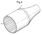
- Each fitted sleeve 9 has an inner metal liner 10 and is preshaped to fit over the ends of the extremity box 3.
- the fitted sleeve 9 is either made from a sufficiently stretchable material so that it may be drawn over and fit tightly around the ends of the extremity box, a so-called "glove fit", or it is made from a heat-shrinkable material.
- a heat-shrinkable sleeve is used in which the outer layer of the sleeve is made from radiation cross-linked polyethylene manufactured by Raychem.
- FIG. 4 An example of this is shown in Figure 4. Inside the sleeve 9 is a circumferentially fluted concertina-able metal inner liner 10 which provides a first barrier against the ingress of hydrogen.
- This design allows the metal liner to be compressed onto the ends of the sheets 8 without splitting when an only slightly oversize (say 1-2 mm excess diameter) heat-shrinkable sleeve shrinks in response to applied heat.
- suitable metals include aluminium and plated nickel-copper tin.
- the fitted sleeve 9 prevents ingress of hydrogen directly into the extremity box 3 or submarine cable 4 and because of its substantial (preferably over 100 mm) overlap over the wrapping 8 provides a long path length for ingress of hydrogen to the box via the otherwise exposed end portions of the metal wrapping 8.
- the concertina-ed metal liner does not lie flat on the cylindrical surface of the wrapping, but the gravules between the flutings are filled with adhesive acting over the substantial leak path, to block hydrogen ingress.
- the fitted sleeve 9 is bonded to the polyethylene casing 5 of the extremity box 3 and of submarine cable 4 by an adhesive, preferably a hot-melt adhesive or an epoxy adhesive as described above.
- the shrinking of a heat-shrinkable sleeve 9 the bonding of its adhesive and the bonding of that of the metal sheet 8 can all be achieved in a single heat-treatment as for example with a blowtorch (completion being indicated by the start of extrusion of adhesive past the ends of sleeve 9) or, preferably because more controlledly, in an oven.
- the sea-earth may be integral with the branching unit 1 itself, for example being a metal ring around the body of the branching unit 1, or being exposed metal armour 11.
Landscapes
- Physics & Mathematics (AREA)
- General Physics & Mathematics (AREA)
- Optics & Photonics (AREA)
- Cable Accessories (AREA)
- Mechanical Coupling Of Light Guides (AREA)
- Light Guides In General And Applications Therefor (AREA)
- Insulated Conductors (AREA)
Abstract
Description
Claims (10)
- A submarine casing for a submarine optical cable, comprising a bonded metal sheath to reduce ingress of hydrogen into the casing.
- A submarine casing according to claim 1, in which the metal sheath comprises a metal sheet wrapped at least once around the casing.
- A submarine casing according to claim 1 or claim 2, in which the metal sheath comprises a sleeve with a metal layer.
- A submarine casing according to claim 3, in which the sleeve is of a heat-shrinkable material having a circumferentially concertina-ed metal inner liner as the metal layer.
- A submarine casing according to claim 3 or claim 4, in which the metal sheath comprises the combination of a said metal sheet wrapped at least once around the casing and a said sleeve overlapping a longitudinal end of the wrapped sheet.
- A submarine casing according to any preceding claim, in which the metal sheath is bonded onto an outer surface of the casing by an adhesive.
- A submarine casing according to any one of the preceding claims in a submarine branching unit for a submarine optical cable.
- A submarine casing according to any one of the preceding claims in a submarine cable connector for a submarine optical cable.
- A submarine casing according to claim 7 or claim 8, with a sea-earth integral with the branching unit or cable connector.
- A method of manufacturing a submarine casing for an optical cable comprising the step of bonding a metal layer at an outer surface of the casing to form a metal sheath around the casing.
Applications Claiming Priority (2)
| Application Number | Priority Date | Filing Date | Title |
|---|---|---|---|
| GB9912746 | 1999-06-01 | ||
| GBGB9912746.6A GB9912746D0 (en) | 1999-06-01 | 1999-06-01 | A submarine casing |
Publications (2)
| Publication Number | Publication Date |
|---|---|
| EP1059549A1 true EP1059549A1 (en) | 2000-12-13 |
| EP1059549B1 EP1059549B1 (en) | 2014-11-26 |
Family
ID=10854554
Family Applications (1)
| Application Number | Title | Priority Date | Filing Date |
|---|---|---|---|
| EP00304508.5A Expired - Lifetime EP1059549B1 (en) | 1999-06-01 | 2000-05-26 | Submarine casing for a submarine optical connector with a bonded metal sheath which comprises a metal sheet and a sleeve with an inner metal liner |
Country Status (4)
| Country | Link |
|---|---|
| US (1) | US6621963B1 (en) |
| EP (1) | EP1059549B1 (en) |
| JP (1) | JP4245255B2 (en) |
| GB (1) | GB9912746D0 (en) |
Cited By (2)
| Publication number | Priority date | Publication date | Assignee | Title |
|---|---|---|---|---|
| EP1312962A3 (en) * | 2001-10-31 | 2004-09-29 | Alcatel | Earthing electrode assembly for submerged electrical apparatus |
| EP1735649A4 (en) * | 2004-03-12 | 2009-04-22 | Huawei Marine Networks Co Ltd | Overmolded, ultra-small form factor |
Citations (4)
| Publication number | Priority date | Publication date | Assignee | Title |
|---|---|---|---|---|
| JPS53111495A (en) | 1977-03-09 | 1978-09-29 | Nippon Telegr & Teleph Corp <Ntt> | Jointing method of submarine coaxial cable |
| JPS6461710A (en) | 1987-09-01 | 1989-03-08 | Sumitomo Electric Industries | Connecting box for optical fiber cable |
| EP0744806A1 (en) | 1995-05-26 | 1996-11-27 | AT&T IPM Corp. | Method for providing submarine cable joint protection and insulation using heat shrinkable tubing |
| EP0980013A2 (en) * | 1998-08-10 | 2000-02-16 | Alcatel | Seal for underwater cable joint |
Family Cites Families (11)
| Publication number | Priority date | Publication date | Assignee | Title |
|---|---|---|---|---|
| FR2519149B1 (en) * | 1981-12-30 | 1985-07-26 | Cables De Lyon Geoffroy Delore | DEVICE FOR JOINING THE END OF TWO OPTICAL FIBER SUBMARINE CABLES AND ITS MANUFACTURING METHOD |
| US4606603A (en) * | 1983-04-07 | 1986-08-19 | Lockheed Corporation | Underwater connector including integral bladder and seal with a set of constricting means |
| US4718747A (en) * | 1984-04-27 | 1988-01-12 | Societa Cavi Pirelli S.P.A. | Optical fiber and cable with hydrogen combining layer |
| GB8412721D0 (en) * | 1984-05-18 | 1984-06-27 | Standard Telephones Cables Ltd | Fibre optic cables |
| US4696543A (en) * | 1984-05-22 | 1987-09-29 | Standard Telephone And Cables, Plc | Optical fiber cable having a low permeability to hydrogen |
| JPS60249105A (en) * | 1984-05-25 | 1985-12-09 | Kokusai Denshin Denwa Co Ltd <Kdd> | Construction for detaining optical submarine cable |
| FR2607939B1 (en) * | 1986-12-05 | 1989-02-03 | Cables De Lyon Geoffroy Delore | CONNECTION BOX FOR FIBER OPTIC CABLES |
| ATE155251T1 (en) * | 1991-08-16 | 1997-07-15 | Aofr Pty Ltd | PACKAGING AND PACKAGING OF FIBER OPTICAL COMPONENTS |
| DK0552530T3 (en) * | 1992-01-24 | 1996-09-16 | Alcatel Submarine Systems Bv | Underwater create noise Ring |
| IT1264902B1 (en) * | 1993-06-29 | 1996-10-17 | Pirelli Cavi Spa | HYDROGEN-ABSORBENT COMPOSITION FOR FIBER OPTIC CABLES AND FIBER OPTIC CABLE INCLUDING THE ABOVE COMPOSITION |
| CA2161168C (en) * | 1994-12-20 | 2001-08-14 | John James Blee | Optical fiber cable for underwater use using terrestrial optical fiber cable |
-
1999
- 1999-06-01 GB GBGB9912746.6A patent/GB9912746D0/en not_active Ceased
-
2000
- 2000-05-25 JP JP2000154536A patent/JP4245255B2/en not_active Expired - Lifetime
- 2000-05-26 EP EP00304508.5A patent/EP1059549B1/en not_active Expired - Lifetime
- 2000-05-31 US US09/583,286 patent/US6621963B1/en not_active Expired - Lifetime
Patent Citations (4)
| Publication number | Priority date | Publication date | Assignee | Title |
|---|---|---|---|---|
| JPS53111495A (en) | 1977-03-09 | 1978-09-29 | Nippon Telegr & Teleph Corp <Ntt> | Jointing method of submarine coaxial cable |
| JPS6461710A (en) | 1987-09-01 | 1989-03-08 | Sumitomo Electric Industries | Connecting box for optical fiber cable |
| EP0744806A1 (en) | 1995-05-26 | 1996-11-27 | AT&T IPM Corp. | Method for providing submarine cable joint protection and insulation using heat shrinkable tubing |
| EP0980013A2 (en) * | 1998-08-10 | 2000-02-16 | Alcatel | Seal for underwater cable joint |
Non-Patent Citations (3)
| Title |
|---|
| PATENT ABSTRACTS OF JAPAN vol. 002, no. 143 (E - 074) 25 November 1978 (1978-11-25) * |
| PATENT ABSTRACTS OF JAPAN vol. 013, no. 203 (P - 870) 15 May 1989 (1989-05-15) * |
| PATENT ABSTRACTS OF JAPAN vol. 013, no. 269 (P - 888) 21 June 1989 (1989-06-21) * |
Cited By (3)
| Publication number | Priority date | Publication date | Assignee | Title |
|---|---|---|---|---|
| EP1312962A3 (en) * | 2001-10-31 | 2004-09-29 | Alcatel | Earthing electrode assembly for submerged electrical apparatus |
| EP1674908A1 (en) * | 2001-10-31 | 2006-06-28 | Alcatel | Earthing electrode assembly for submerged electrical apparatus |
| EP1735649A4 (en) * | 2004-03-12 | 2009-04-22 | Huawei Marine Networks Co Ltd | Overmolded, ultra-small form factor |
Also Published As
| Publication number | Publication date |
|---|---|
| GB9912746D0 (en) | 1999-08-04 |
| US6621963B1 (en) | 2003-09-16 |
| JP4245255B2 (en) | 2009-03-25 |
| JP2001025147A (en) | 2001-01-26 |
| EP1059549B1 (en) | 2014-11-26 |
Similar Documents
| Publication | Publication Date | Title |
|---|---|---|
| US4156104A (en) | Submarine cable for optical communications | |
| AU2007201817B2 (en) | Optical cable shield layer connection | |
| US4227770A (en) | Submarine fiber optic cable | |
| US4371234A (en) | Submarine optical cable | |
| US4846545A (en) | Fiber optic cable connection | |
| JPH06103833A (en) | Hybrid cable | |
| EP0193780B1 (en) | Submarine cable for optical-fibres telecommunications | |
| US4239336A (en) | Optical communication cable | |
| JPH0451803B2 (en) | ||
| GB2029048A (en) | Optical fibre submarine cable | |
| JPS61209410A (en) | Optical fiber communication submarine cable | |
| US4717232A (en) | Submarine cable joint with optoelectronic repeaters | |
| US6272273B1 (en) | Hermetic cable joint | |
| US4427262A (en) | Armor wire splices | |
| US4621168A (en) | Submarine cable joint housing | |
| US6621963B1 (en) | Submarine casing for a submarine optical cable | |
| US4722588A (en) | Joint for optical fiber submarine cables | |
| AU664285B2 (en) | Splicing box for submarine cable | |
| US4064358A (en) | Termination for connecting a submarine coaxial cable to a submergible housing | |
| GB2107896A (en) | Electric cable | |
| AU2012257970B2 (en) | Method for making a splice between optical fibres in a joint device for electrical cables | |
| EP1553675A2 (en) | Armouring joint, an armoured cable joint and a method for jointing armouring of two armoured cables | |
| US20230400638A1 (en) | Joint assembly for power cables having an optical fiber cable embedded at different radial positions, joint system and method for installing such a joint assembly | |
| JPH083565B2 (en) | Optical cable connection | |
| RU2228568C2 (en) | Y-splice box for branching low-frequency conductors from combined copper-optical communication cable passing transit optical fibers and high-frequency copper conductors |
Legal Events
| Date | Code | Title | Description |
|---|---|---|---|
| PUAI | Public reference made under article 153(3) epc to a published international application that has entered the european phase |
Free format text: ORIGINAL CODE: 0009012 |
|
| AK | Designated contracting states |
Kind code of ref document: A1 Designated state(s): AT BE CH CY DE DK ES FI FR GB GR IE IT LI LU MC NL PT SE |
|
| AX | Request for extension of the european patent |
Free format text: AL;LT;LV;MK;RO;SI |
|
| 17P | Request for examination filed |
Effective date: 20010613 |
|
| AKX | Designation fees paid |
Free format text: AT BE CH CY DE DK ES FI FR GB GR IE IT LI LU MC NL PT SE |
|
| RAP1 | Party data changed (applicant data changed or rights of an application transferred) |
Owner name: ALCATEL LUCENT |
|
| 17Q | First examination report despatched |
Effective date: 20071122 |
|
| RAP1 | Party data changed (applicant data changed or rights of an application transferred) |
Owner name: ALCATEL LUCENT |
|
| 111Z | Information provided on other rights and legal means of execution |
Free format text: AT BE CH CY DE DK ES FI FR GB GR IE IT LI LU MC NL PT SE Effective date: 20130410 |
|
| GRAJ | Information related to disapproval of communication of intention to grant by the applicant or resumption of examination proceedings by the epo deleted |
Free format text: ORIGINAL CODE: EPIDOSDIGR1 |
|
| GRAP | Despatch of communication of intention to grant a patent |
Free format text: ORIGINAL CODE: EPIDOSNIGR1 |
|
| INTG | Intention to grant announced |
Effective date: 20140708 |
|
| RAP1 | Party data changed (applicant data changed or rights of an application transferred) |
Owner name: ALCATEL LUCENT |
|
| GRAS | Grant fee paid |
Free format text: ORIGINAL CODE: EPIDOSNIGR3 |
|
| GRAA | (expected) grant |
Free format text: ORIGINAL CODE: 0009210 |
|
| D11X | Information provided on other rights and legal means of execution (deleted) | ||
| AK | Designated contracting states |
Kind code of ref document: B1 Designated state(s): AT BE CH CY DE DK ES FI FR GB GR IE IT LI LU MC NL PT SE |
|
| REG | Reference to a national code |
Ref country code: GB Ref legal event code: FG4D |
|
| REG | Reference to a national code |
Ref country code: CH Ref legal event code: EP |
|
| REG | Reference to a national code |
Ref country code: AT Ref legal event code: REF Ref document number: 698516 Country of ref document: AT Kind code of ref document: T Effective date: 20141215 |
|
| REG | Reference to a national code |
Ref country code: IE Ref legal event code: FG4D |
|
| REG | Reference to a national code |
Ref country code: DE Ref legal event code: R096 Ref document number: 60048791 Country of ref document: DE Effective date: 20150108 |
|
| REG | Reference to a national code |
Ref country code: NL Ref legal event code: VDEP Effective date: 20141126 |
|
| REG | Reference to a national code |
Ref country code: AT Ref legal event code: MK05 Ref document number: 698516 Country of ref document: AT Kind code of ref document: T Effective date: 20141126 |
|
| PG25 | Lapsed in a contracting state [announced via postgrant information from national office to epo] |
Ref country code: ES Free format text: LAPSE BECAUSE OF FAILURE TO SUBMIT A TRANSLATION OF THE DESCRIPTION OR TO PAY THE FEE WITHIN THE PRESCRIBED TIME-LIMIT Effective date: 20141126 Ref country code: NL Free format text: LAPSE BECAUSE OF FAILURE TO SUBMIT A TRANSLATION OF THE DESCRIPTION OR TO PAY THE FEE WITHIN THE PRESCRIBED TIME-LIMIT Effective date: 20141126 Ref country code: FI Free format text: LAPSE BECAUSE OF FAILURE TO SUBMIT A TRANSLATION OF THE DESCRIPTION OR TO PAY THE FEE WITHIN THE PRESCRIBED TIME-LIMIT Effective date: 20141126 Ref country code: PT Free format text: LAPSE BECAUSE OF FAILURE TO SUBMIT A TRANSLATION OF THE DESCRIPTION OR TO PAY THE FEE WITHIN THE PRESCRIBED TIME-LIMIT Effective date: 20150326 |
|
| REG | Reference to a national code |
Ref country code: FR Ref legal event code: PLFP Year of fee payment: 16 |
|
| PG25 | Lapsed in a contracting state [announced via postgrant information from national office to epo] |
Ref country code: SE Free format text: LAPSE BECAUSE OF FAILURE TO SUBMIT A TRANSLATION OF THE DESCRIPTION OR TO PAY THE FEE WITHIN THE PRESCRIBED TIME-LIMIT Effective date: 20141126 Ref country code: CY Free format text: LAPSE BECAUSE OF FAILURE TO SUBMIT A TRANSLATION OF THE DESCRIPTION OR TO PAY THE FEE WITHIN THE PRESCRIBED TIME-LIMIT Effective date: 20141126 Ref country code: GR Free format text: LAPSE BECAUSE OF FAILURE TO SUBMIT A TRANSLATION OF THE DESCRIPTION OR TO PAY THE FEE WITHIN THE PRESCRIBED TIME-LIMIT Effective date: 20150227 Ref country code: AT Free format text: LAPSE BECAUSE OF FAILURE TO SUBMIT A TRANSLATION OF THE DESCRIPTION OR TO PAY THE FEE WITHIN THE PRESCRIBED TIME-LIMIT Effective date: 20141126 |
|
| PG25 | Lapsed in a contracting state [announced via postgrant information from national office to epo] |
Ref country code: DK Free format text: LAPSE BECAUSE OF FAILURE TO SUBMIT A TRANSLATION OF THE DESCRIPTION OR TO PAY THE FEE WITHIN THE PRESCRIBED TIME-LIMIT Effective date: 20141126 |
|
| REG | Reference to a national code |
Ref country code: DE Ref legal event code: R097 Ref document number: 60048791 Country of ref document: DE |
|
| PLBE | No opposition filed within time limit |
Free format text: ORIGINAL CODE: 0009261 |
|
| STAA | Information on the status of an ep patent application or granted ep patent |
Free format text: STATUS: NO OPPOSITION FILED WITHIN TIME LIMIT |
|
| 26N | No opposition filed |
Effective date: 20150827 |
|
| PG25 | Lapsed in a contracting state [announced via postgrant information from national office to epo] |
Ref country code: IT Free format text: LAPSE BECAUSE OF FAILURE TO SUBMIT A TRANSLATION OF THE DESCRIPTION OR TO PAY THE FEE WITHIN THE PRESCRIBED TIME-LIMIT Effective date: 20141126 |
|
| REG | Reference to a national code |
Ref country code: CH Ref legal event code: PL |
|
| PG25 | Lapsed in a contracting state [announced via postgrant information from national office to epo] |
Ref country code: LU Free format text: LAPSE BECAUSE OF FAILURE TO SUBMIT A TRANSLATION OF THE DESCRIPTION OR TO PAY THE FEE WITHIN THE PRESCRIBED TIME-LIMIT Effective date: 20150526 Ref country code: MC Free format text: LAPSE BECAUSE OF FAILURE TO SUBMIT A TRANSLATION OF THE DESCRIPTION OR TO PAY THE FEE WITHIN THE PRESCRIBED TIME-LIMIT Effective date: 20141126 Ref country code: LI Free format text: LAPSE BECAUSE OF NON-PAYMENT OF DUE FEES Effective date: 20150531 Ref country code: CH Free format text: LAPSE BECAUSE OF NON-PAYMENT OF DUE FEES Effective date: 20150531 |
|
| REG | Reference to a national code |
Ref country code: IE Ref legal event code: MM4A |
|
| PG25 | Lapsed in a contracting state [announced via postgrant information from national office to epo] |
Ref country code: IE Free format text: LAPSE BECAUSE OF NON-PAYMENT OF DUE FEES Effective date: 20150526 |
|
| REG | Reference to a national code |
Ref country code: FR Ref legal event code: PLFP Year of fee payment: 17 |
|
| REG | Reference to a national code |
Ref country code: FR Ref legal event code: PLFP Year of fee payment: 18 |
|
| PG25 | Lapsed in a contracting state [announced via postgrant information from national office to epo] |
Ref country code: BE Free format text: LAPSE BECAUSE OF FAILURE TO SUBMIT A TRANSLATION OF THE DESCRIPTION OR TO PAY THE FEE WITHIN THE PRESCRIBED TIME-LIMIT Effective date: 20141126 |
|
| REG | Reference to a national code |
Ref country code: FR Ref legal event code: PLFP Year of fee payment: 19 |
|
| PGFP | Annual fee paid to national office [announced via postgrant information from national office to epo] |
Ref country code: DE Payment date: 20190514 Year of fee payment: 20 |
|
| PGFP | Annual fee paid to national office [announced via postgrant information from national office to epo] |
Ref country code: FR Payment date: 20190410 Year of fee payment: 20 |
|
| PGFP | Annual fee paid to national office [announced via postgrant information from national office to epo] |
Ref country code: GB Payment date: 20190522 Year of fee payment: 20 |
|
| REG | Reference to a national code |
Ref country code: DE Ref legal event code: R071 Ref document number: 60048791 Country of ref document: DE |
|
| REG | Reference to a national code |
Ref country code: GB Ref legal event code: PE20 Expiry date: 20200525 |
|
| PG25 | Lapsed in a contracting state [announced via postgrant information from national office to epo] |
Ref country code: GB Free format text: LAPSE BECAUSE OF EXPIRATION OF PROTECTION Effective date: 20200525 |