EP1059501A2 - Direct smelting vessel - Google Patents
Direct smelting vessel Download PDFInfo
- Publication number
- EP1059501A2 EP1059501A2 EP00112266A EP00112266A EP1059501A2 EP 1059501 A2 EP1059501 A2 EP 1059501A2 EP 00112266 A EP00112266 A EP 00112266A EP 00112266 A EP00112266 A EP 00112266A EP 1059501 A2 EP1059501 A2 EP 1059501A2
- Authority
- EP
- European Patent Office
- Prior art keywords
- section
- vessel
- gas
- vessel defined
- gas chamber
- Prior art date
- Legal status (The legal status is an assumption and is not a legal conclusion. Google has not performed a legal analysis and makes no representation as to the accuracy of the status listed.)
- Granted
Links
Images


Classifications
-
- C—CHEMISTRY; METALLURGY
- C21—METALLURGY OF IRON
- C21B—MANUFACTURE OF IRON OR STEEL
- C21B11/00—Making pig-iron other than in blast furnaces
- C21B11/08—Making pig-iron other than in blast furnaces in hearth-type furnaces
-
- C—CHEMISTRY; METALLURGY
- C21—METALLURGY OF IRON
- C21B—MANUFACTURE OF IRON OR STEEL
- C21B13/00—Making spongy iron or liquid steel, by direct processes
- C21B13/0006—Making spongy iron or liquid steel, by direct processes obtaining iron or steel in a molten state
- C21B13/0026—Making spongy iron or liquid steel, by direct processes obtaining iron or steel in a molten state introduction of iron oxide in the flame of a burner or a hot gas stream
-
- C—CHEMISTRY; METALLURGY
- C21—METALLURGY OF IRON
- C21B—MANUFACTURE OF IRON OR STEEL
- C21B13/00—Making spongy iron or liquid steel, by direct processes
- C21B13/0006—Making spongy iron or liquid steel, by direct processes obtaining iron or steel in a molten state
-
- F—MECHANICAL ENGINEERING; LIGHTING; HEATING; WEAPONS; BLASTING
- F27—FURNACES; KILNS; OVENS; RETORTS
- F27B—FURNACES, KILNS, OVENS OR RETORTS IN GENERAL; OPEN SINTERING OR LIKE APPARATUS
- F27B3/00—Hearth-type furnaces, e.g. of reverberatory type; Electric arc furnaces ; Tank furnaces
- F27B3/10—Details, accessories or equipment, e.g. dust-collectors, specially adapted for hearth-type furnaces
- F27B3/22—Arrangements of air or gas supply devices
- F27B3/225—Oxygen blowing
-
- F—MECHANICAL ENGINEERING; LIGHTING; HEATING; WEAPONS; BLASTING
- F27—FURNACES; KILNS; OVENS; RETORTS
- F27D—DETAILS OR ACCESSORIES OF FURNACES, KILNS, OVENS OR RETORTS, IN SO FAR AS THEY ARE OF KINDS OCCURRING IN MORE THAN ONE KIND OF FURNACE
- F27D17/00—Arrangements for using waste heat; Arrangements for using, or disposing of, waste gases
- F27D17/30—Arrangements for extraction or collection of waste gases; Hoods therefor
-
- F—MECHANICAL ENGINEERING; LIGHTING; HEATING; WEAPONS; BLASTING
- F27—FURNACES; KILNS; OVENS; RETORTS
- F27B—FURNACES, KILNS, OVENS OR RETORTS IN GENERAL; OPEN SINTERING OR LIKE APPARATUS
- F27B3/00—Hearth-type furnaces, e.g. of reverberatory type; Electric arc furnaces ; Tank furnaces
- F27B3/10—Details, accessories or equipment, e.g. dust-collectors, specially adapted for hearth-type furnaces
-
- F—MECHANICAL ENGINEERING; LIGHTING; HEATING; WEAPONS; BLASTING
- F27—FURNACES; KILNS; OVENS; RETORTS
- F27B—FURNACES, KILNS, OVENS OR RETORTS IN GENERAL; OPEN SINTERING OR LIKE APPARATUS
- F27B3/00—Hearth-type furnaces, e.g. of reverberatory type; Electric arc furnaces ; Tank furnaces
- F27B3/10—Details, accessories or equipment, e.g. dust-collectors, specially adapted for hearth-type furnaces
- F27B3/12—Working chambers or casings; Supports therefor
-
- F—MECHANICAL ENGINEERING; LIGHTING; HEATING; WEAPONS; BLASTING
- F27—FURNACES; KILNS; OVENS; RETORTS
- F27D—DETAILS OR ACCESSORIES OF FURNACES, KILNS, OVENS OR RETORTS, IN SO FAR AS THEY ARE OF KINDS OCCURRING IN MORE THAN ONE KIND OF FURNACE
- F27D3/00—Charging; Discharging; Manipulation of charge
- F27D3/15—Tapping equipment; Equipment for removing or retaining slag
- F27D3/1545—Equipment for removing or retaining slag
-
- F—MECHANICAL ENGINEERING; LIGHTING; HEATING; WEAPONS; BLASTING
- F27—FURNACES; KILNS; OVENS; RETORTS
- F27D—DETAILS OR ACCESSORIES OF FURNACES, KILNS, OVENS OR RETORTS, IN SO FAR AS THEY ARE OF KINDS OCCURRING IN MORE THAN ONE KIND OF FURNACE
- F27D3/00—Charging; Discharging; Manipulation of charge
- F27D3/18—Charging particulate material using a fluid carrier
-
- Y—GENERAL TAGGING OF NEW TECHNOLOGICAL DEVELOPMENTS; GENERAL TAGGING OF CROSS-SECTIONAL TECHNOLOGIES SPANNING OVER SEVERAL SECTIONS OF THE IPC; TECHNICAL SUBJECTS COVERED BY FORMER USPC CROSS-REFERENCE ART COLLECTIONS [XRACs] AND DIGESTS
- Y02—TECHNOLOGIES OR APPLICATIONS FOR MITIGATION OR ADAPTATION AGAINST CLIMATE CHANGE
- Y02P—CLIMATE CHANGE MITIGATION TECHNOLOGIES IN THE PRODUCTION OR PROCESSING OF GOODS
- Y02P10/00—Technologies related to metal processing
- Y02P10/10—Reduction of greenhouse gas [GHG] emissions
- Y02P10/134—Reduction of greenhouse gas [GHG] emissions by avoiding CO2, e.g. using hydrogen
Definitions
- the present invention relates to a direct smelting vessel for producing molten metal (which term includes metal alloys) from a metalliferous feed material such as ores and partly reduced ores.
- the present invention relates particularly to a vessel that can be used for molten bath-based direct smelting processes.
- melting is understood herein to mean thermal processing wherein chemical reactions that reduce metal oxides take place to produce liquid metal.
- direct smelting process is understood herein to mean a process that produces a molten metal directly from a metalliferous feed material, such as iron ore and partly reduced iron ore.
- the present invention relates particularly to off-gas ducts for direct smelting vessels.
- An object of the present invention is to provide an off-gas duct which minimises loss of molten material and solids entrained with off-gas.
- a direct smelting vessel which is adapted to contain a molten bath of metal and slag and includes: a hearth; side walls that extend upwardly from the hearth; a roof; and an off-gas duct extending from an upper section of the vessel for discharging from the vessel an off-gas that is produced during a direct smelting process operated in the vessel, which off-gas duct includes:
- off-gas In use, off-gas is forced to undergo a substantial change in direction in order to enter the first section. It is believed that, as a consequence, molten material and solids that are entrained in the off-gas contact and deposit on: (i) walls of the vessel that are at or in the region of the inlet end, and (ii) walls (particularly upper walls) of the first section at or in the region of the inlet end; and thereby separate from the off-gas. Molten material and solids that deposit on these walls move downwardly into the vessel.
- the slightly inclined first section avoids the potentially serious problem of solid accretions falling back into the vessel and damaging equipment such as lances/tuyeres while a direct smelting process is being operated in the vessel or after a shut down. Such fall back is also a potentially serious safety issue for persons carrying out maintenance work in the vessel during a shut down.
- the first section is formed having regard to operating conditions in the vessel so that at least a substantial part of the molten material that enters the first section with the off-gas is molten at the end of the slightly inclined first section. This feature ensures that there is minimal built-up of solid accretions in the first section.
- the first section is formed so that the temperature drop along the length of the first section is less than 100°C and the overall temperature is maintained above the melting points of the molten material.
- the amount of entrained material (molten and solids) in the off-gas discharged from the second section is less than 15g, more preferably less than 10g, per Nm 3 off-gas.
- the relatively slight upward inclination of the first section is less than 30°, more preferably less than 20°, to the horizontal.
- the angle of inclination be less than 10°.
- the relatively steep inclination of the second section is 80-90° to the horizontal.
- the vessel includes a dead end bond that connects the first and second sections.
- the dead end bend includes an access port in the dead end.
- the vessel includes an off-gas chamber extending upwardly from the roof and the first section of the off-gas duct extends from the off-gas chamber.
- the first section of the off-gas duct extends from a side wall of the off-gas chamber.
- the ratio of the length of the first section to the minimum width dimension of the first section is at least 2:1, where the length of the first section is measured between the intersection of centrelines of the first and second sections and the intersections of the centreline of the first section and a vertical line through the inlet end of the first section.
- the intersection of the centreline of the first section and a vertical centreline of the off-gas chamber is the measurement point at the inlet end of the first section.
- the first and second sections are cylindrical and the minimum width dimension of the first section referred to in the preceding paragraph is the diameter of the first section.
- the second section is formed so that the temperature drop along the length of the second section is sufficient to solidify at least a substantial part of any molten material that is in off-gas flowing through the second section before the off-gas reaches the end of the second section.
- This ensures that there is minimal, if any, carry over of molten material into downstream off-gas processing apparatus, such as hot cyclones and hot scrubbers, that may be affected adversely by molten material in off-gas.
- the off-gas chamber is located centrally.
- the vessel includes at least one lance for injecting oxygen-containing gas into the vessel which extends downwardly through the off-gas chamber into the vessel.
- the ratio of the minimum width dimensions of the side walls of the vessel and of the off-gas chamber is at least 1.5:1. In situations where the oxygen-containing gas injection lance or lances extend downwardly through the off-gas chamber, preferably the ratio is 1.5:1 to 2:1. In situations where the gas injection lance or lances are not located to extend through the off-gas chamber the ratio of minimum width dimensions may be up to 4:1.
- the roof is upwardly inclined from the side walls at an angle in the range of 30 to 50° to a horizontal axis (ie an included angle of 120 to 130° measured between the side walls and the roof).
- the angle of inclination is 40° to the horizontal axis.
- the side walls are cylindrical and the roof is frusto-conical and extends from an upper end of the side walls and terminates in the off-gas chamber.
- the minimum width dimension of the side walls of the vessel is 8 meters.
- the vessel shown in Figure 1 has a hearth that includes a base 3 and sides 55 formed from refractory bricks; side walls 5 which form a generally cylindrical barrel extending upwardly from the sides 55 of the hearth and which include an upper barrel section 51 and a lower barrel section 53; a roof 7; an off-gas duct 9 extending from an upper section of the vessels a forehearth 77 for discharging molten metal continuously; and a tap-hole 61 for discharging molten slag.
- the off-gas duct 9 includes a slightly upwardly inclined first section 31 that extends from an inlet end 63 at an angle ⁇ of 7° to the horizontal and a steep second section 33 that extends vertically from the other end of the first section 31. Both sections 31, 33 are cylindrical.
- the first section 31 is formed, having regard to the operating conditions in the vessel and other relevant factors, so that molten material that enters the first section remains molten along the length of the first section.
- the first section is formed so that the temperature in the first section, particularly in the region of the wall, is above that at which the molten material solidifies.
- the second section 33 is formed so that the temperature drop along the length of the second section is sufficient to solidify at least a substantial part of any molten material that is in off-gas flowing through the second section 33 by the time that the molten material reaches the end of the second section 33.
- the vessel contains a molten bath of iron and slag which includes a layer 15 of molten metal and a layer 16 of molten slag on the metal layer 15.
- the arrow marked by the numeral 17 indicates the position of quiescent surface of the metal layer 15 and the arrow marked by the numeral 19 indicates the position of the quiescent surface of the slag layer 16.
- the term "quiescent surface” is understood to mean the surface when there is no injection of gas and solids into the vessel.
- the vessel also includes 2 solids injection lances/tuyeres 11 extending downwardly and inwardly at an angle of 30°-60° to the vertical through the side walls 5 and into the slag layer 16.
- the position of the lances/tuyeres 11 is selected so that the lower ends are above the quiescent surface 17 of the metal layer 15.
- iron ore typically fines
- solid carbonaceous material typically coal
- fluxes typically lime and magnesia
- a carrier gas typically N 2
- the momentum of the solid material/carrier gas causes the solid material and the carrier gas to penetrate the metal layer 15.
- the coal is devolatilised and thereby produces gas in the metal layer 15.
- Carbon partially dissolves into the metal and partially remains as solid carbon.
- the iron ore is smelted to metal and the smelting reaction generates carbon monoxide gas.
- the gases transported into the metal layer 15 and generated via devolatilisation and smelting produce significant buoyancy uplift of molten metal, solid carbon, and slag (drawn into the metal layer 15 as a consequence of solid/gas/injection) from the metal layer 15 which generates an upward movement of splashes, droplets and streams of molten metal and slag, and these splashes, droplets, and streams entrain slag as they move through the slag layer 16.
- the buoyancy uplift of molten metal, solid carbon and slag causes substantial agitation in the metal layer 15 and the slag layer 16, with the result that the slag layer 16 expands in volume and has a surface indicated by the arrow 30.
- the extent of agitation is such that there is reasonably uniform temperature in the metal and the slag regions - typically, 1450-1550°C with a temperature variation of the order of 30°C.
- the slag layer 16 is a liquid continuous volume, with gas bubbles therein, and the transition zone 23 is a gas continuous volume with splashes, droplets, and streams of molten metal and slag.
- the vessel further includes a lance 13 for injecting an oxygen-containing gas (typically pre-heated oxygen enriched air) which is centrally located and extends vertically downwardly into the vessel.
- an oxygen-containing gas typically pre-heated oxygen enriched air
- the position of the lance 13 and the gas flow rate through the lance 13 are selected so that the oxygen-containing gas penetrates the central region of the transition zone 23 and maintains an essentially metal/slag free space 25 around the end of the lance 13.
- the injection of the oxygen-containing gas via the lance 13 post-combusts reaction gases CO and H 2 in the transition zone 23 and in the free space 25 around the end of the lance 13 and generates high temperatures of the order of 2000°C or higher in the gas space.
- the heat is transferred to the ascending and descending splashes, droplets, and streams of molten material in the region of gas injection and the heat is then partially transferred to the metal layer 15 when the metal/slag returns to the metal layer 15.
- the above described process generates substantial volumes of off-gas which are at temperatures in the range of 1550 to 1650°C and include entrained molten material dad solids.
- the solids in the entrained material are generally in the form of dust.
- the off-gas flows from the top space 71 into the slightly inclined first section 31 of the off-gas duct 9 via the inlet end 63, along the length of the first section 31, around the tight radius corner at the end of this section, and then upwardly through the second section 33.
- the off-gas undergoes sharp changes of direction at the inlet end 63 of the first section 31 and at the tight radius corner that joins the first and second sections. As is discussed above, these sharp changes of direction cause molten material and solids that are entrained in the off-gas to contact and deposit on the upper wall of the duct in the circled region A and on the end wall of the duct in the circled region B.
- region A it is believed that the deposited molten material remains molten and flows downwardly into the vessel and that the deposited solids are carried by the molten material back into the vessel.
- region B it is believed that part of the molten material remains molten and the remainder of the molten material solidifies.
- the molten material that remains molten flows down the end wall into the first section 31 and then along the first section 31 and into the vessel.
- the molten material that solidifies progressively builds up on the wall and eventually spalls and falls down into the first section 31.
- the first section 31 By forming the first section 31 so that the temperature along the length of the first section is above that at which the molten material solidifies ensures that at least a substantial part of the solidified material melts and flows down the slight incline and into the vessel. The solids that remain solid are carried by the molten material back into the vessel.
- the above-described off-gas duct 9 makes it possible to remove substantial amounts of entrained molten material and solids from off-gas with the result that the total amount of entrained material (ie molten material and solids) discharged from the section 33 is kept below 15g per Nm 3 of off-gas.
- the slightly inclined first section 31 avoids the potentially serious problem of solid accretions falling back into the vessel and damaging equipment such as lances/tuyeres while a direct smelting process is being operated in the vessel or after a shut down.
- slightly inclined first section 31 makes it possible to leave clear the top of the vessel and thereby enable crane access to remove and reposition the oxygen-containing gas injection lance 13 and otherwise allow crane access to the interior of the vessel via the top of the vessel, as may be required during relining operations.
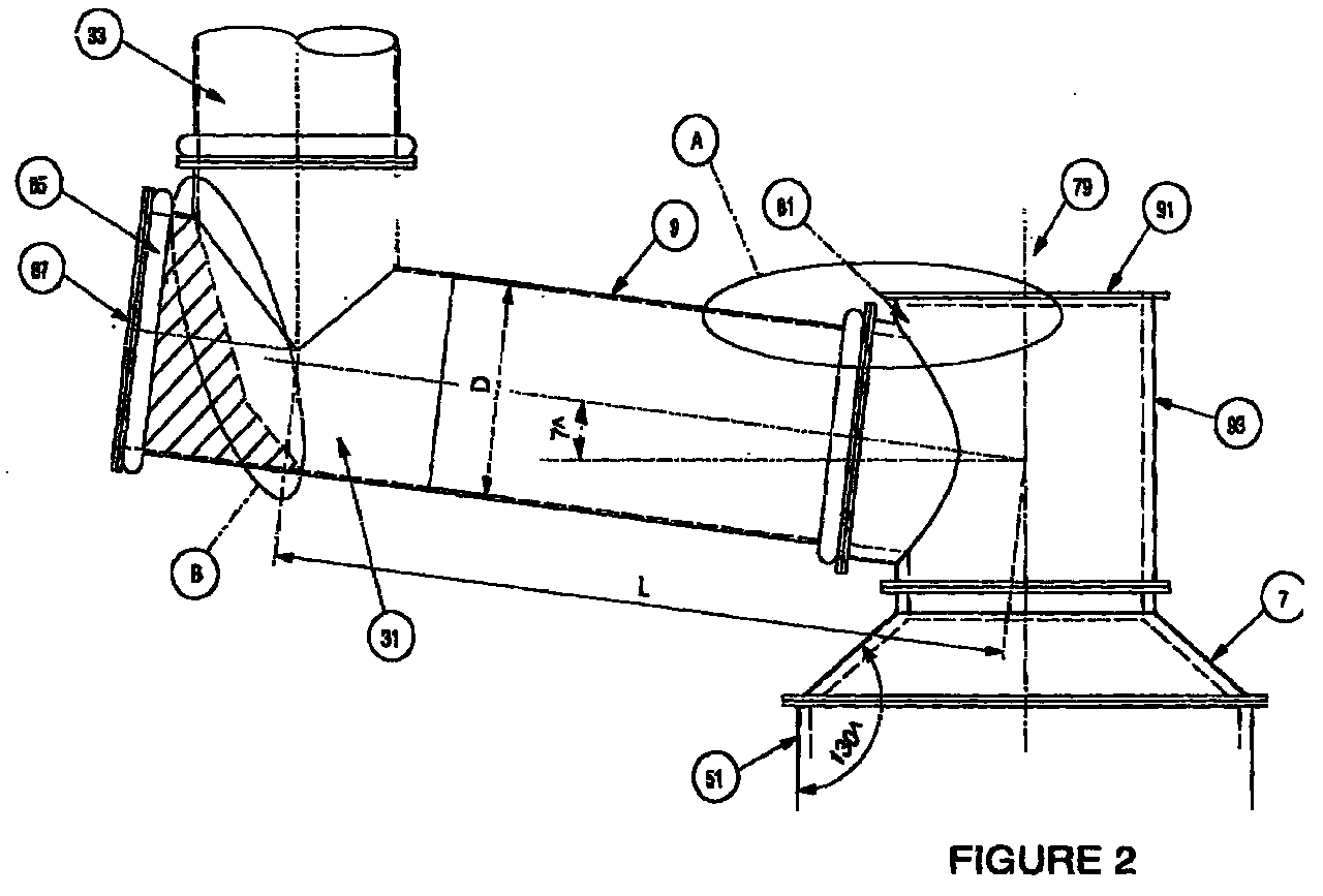
- the basic components, is hearth, side walls, roof and off-gas duct, solids injection lances, and oxygen-containing gas injection lance of the vessel shown in Figure 2 are the same as the vessel shown in Figure 1.
- the basic molten bath-based smelting process operated in the vessel shown in Figure 2 is the same as that described in relation to Figure 1. Accordingly, Figure 2 and the following description of the figure focuses on the differences between two embodiments of the present invention.
- the vessel includes a cylindrical off-gas chamber 79 which extends upwardly from the roof 7 and the off-gas duct 9 extends from the side wall 93 of the off-gas chamber 79.
- a top wall 91 of the off-gas chamber 79 is formed as a removable access port to allow access to the vessel.
- the off-gas chamber 79 is positioned centrally and, accordingly, the roof 7 is frusto-conical in shape and defines an included angle of 130° with the upper barrel section 51 of the side walls 5 of the vessel.
- the ratio of the diameters of the upper barrel section 51 and the off-gas chamber 79 is 1.8:1.
- the oxygen-containing gas injection lance 13 is positioned to extend downwardly through the top wall 91 of off-gas chamber 79.
- the first section 31 of the off-gas duct 9 extends at an angle ⁇ of 7° to the horizontal and the second section 33 extends vertically from the first section 31.
- the dimensions of the first section 31 of the off-gas duct 9 are selected so that the ratio of the length L of the first section 31 (as measured between the intersection of the centrelines of the first and second sections 31, 33 and the intersection of the centreline of the first section and a vertical centreline of the off-gas chamber 79) and the diameter D of the first section 31 is 3.7:1.
- off-gas undergoes significant changes of direction in order to enter the first suction 31 from the off-gas chamber 79 and in order to enter the second section 33 from the first section.
- these significant changes in direction cause deposition of entrained molten material and solids on exposed surfaces of circled regions A and B and facilitates removal of the entrained material (molten and solids) from off-gas.
- the second section 33 of the off-gas duct 9 is positioned in an upper wall of the first section 31 of the off-gas duct 9 so that an end wall 87 of the first section 31 forms a dead end bend and, in use, there is a build-up of entrained material (molten and solids) - as indicated by the shaded section in the figure - which protects the end wall.
- end wall 87 of the first section 31 of the off-gas duct 9 is formed as a removable access port to allow access to the duct.
Landscapes
- Engineering & Computer Science (AREA)
- Chemical & Material Sciences (AREA)
- Manufacturing & Machinery (AREA)
- Materials Engineering (AREA)
- Metallurgy (AREA)
- Organic Chemistry (AREA)
- Mechanical Engineering (AREA)
- General Engineering & Computer Science (AREA)
- Environmental & Geological Engineering (AREA)
- Vertical, Hearth, Or Arc Furnaces (AREA)
- Manufacture Of Iron (AREA)
- Waste-Gas Treatment And Other Accessory Devices For Furnaces (AREA)
- Manufacture And Refinement Of Metals (AREA)
- Feeding, Discharge, Calcimining, Fusing, And Gas-Generation Devices (AREA)
- Treatment Of Steel In Its Molten State (AREA)
- Management, Administration, Business Operations System, And Electronic Commerce (AREA)
- Traffic Control Systems (AREA)
- Sorption Type Refrigeration Machines (AREA)
Abstract
Description
Claims (40)
- A direct smelting vessel which is adapted to contain a molten bath of metal and slag and includes: a hearth; side walls that extend upwardly from the hearth; a roof; and an off-gas duct extending from an upper section of the vessel for discharging from the vessel an off-gas that is produced during a direct smelting process operated in the vessel, which off-gas duct includes:(a) a first section which has a relatively slight upward inclination to the horizontal from an inlet end of the first section; and(b) a second section which extends upwardly from an upper end of the first section at a relatively steep inclination to the horizontal.
- The vessel defined in claim 1 wherein the relatively slight upward inclination of the first section is less than 30° to the horizontal.
- The vessel defined in claim 2 wherein the relatively slight upward inclination of the first section is less than 20° to the horizontal.
- The vessel defined in claim 3 wherein the angle of inclination of the first section is less than 10° to the horizontal.
- The vessel defined in any one of the preceding claims wherein the relatively steep inclination of the second section is 80-90° to the horizontal.
- The vessel defined in any one of the preceding claims wherein the ratio of the length of the first section to a minimum width dimension of the first section is at least 2:1, where the length of the first section is measured between the intersection of centrelines of the first and second sections and the intersection of the centreline of the first section and a vertical line through the inlet end of the first section.
- The vessel defined in any one of the preceding claims includes a dead end bend that connects the first and second sections.
- The vessel defined in claim 6 wherein the dead end bend includes an access port in the dead end.
- The vessel defined in any one of the preceding claims includes an off-gas chamber extending upwardly from the roof and the first section of the off-gas duct extends from the off-gas chamber.
- The vessel defined in claim 9 wherein the ratio of the minimum width dimensions of the side walls of the vessel and of the off-gas chamber is at least 1.5:1.
- The vessel defined in claim 9 or claim 10 wherein the first section of the off-gas duct extends from a side wall of the off-gas chamber.
- The vessel defined in claim 11 wherein the ratio of the length of the first section to the minimum width dimension of the first section is at least 2:1, where the length of the first section is measured between the intersection of centrelines of the first and second sections and the intersections of the centre line of the first section and a vertical centreline of the off-gas chamber.
- The vessel defined in any one of claims 9 to 12 wherein an upper end of the off-gas chamber defines a dead end bend.
- The vessel defined in any one of claims 9 to 13 wherein the off-gas chamber is located centrally.
- The vessel defined in any one of claims 9 to 14 includes at least one lance for injecting oxygen-containing gas into the vessel which extends downwardly through the off-gas chamber into the vessel.
- The vessel defined in any one of the preceding claims wherein the roof is upwardly inclined from the side walls at an angle in the range of 30 to 50° to a horizontal axis (ie an included angle of 120 to 130° measured between the side walls and the roof).
- The vessel defined in claim 16 wherein the angle of inclination is 40° to the horizontal axis.
- The vessel defined in claim 16 or claim 17 wherein the side walls are cylindrical and the roof is frusto-conical and extends from an upper end of the side walls and terminates in the off-gas chamber.
- The vessel defined in any one of the preceding claims wherein the minimum width dimension of the side walls of the vessel is 8 meters.
- A direct smelting vessel which contains a molten bath of metal and slag and includes: a hearth; side walls that extend upwardly from the hearth; a roof; and an off-gas duct extending from an upper section of the vessel which discharges off-gas produced in a direct smelting process operating in the vessel, which off-gas duct includes:(a) a first section which has a relatively slight upward inclination to the horizontal from an inlet end of the first section; and(b) a second section which extends upwardly from an upper end of the first section at a relatively steep inclination to the horizontal.
- The vessel defined in claim 20 wherein the relatively slight upward inclination of the first section is less than 30° to the horizontal.
- The vessel defined in claim 21 wherein the angle of inclination of the first section is less than 10° to the horizontal.
- The vessel defined in any one of claims 20 to 22 wherein the relatively steep inclination of the second section is 80-90° to the horizontal.
- The vessel defined in any one of claims 20 to 23 wherein at least a substantial part of molten material that enters the first section with the off-gas is molten at the end of the first section.
- The vessel defined in any one of claims 20 to 24 wherein the temperature drop along the length of the first section is less than 100°C and the overall temperature within the first section is maintained above the melting points of the molten material, whereby at least a substantial part of the molten material that enters the first section with the off-gas is molten at the end of the first section.
- The vessel defined in any one of claims 20 to 25 wherein the off-gas discharged from the second section of the off-gas duct includes less than 15g/Nm3 entrained material per Nm3 off-gas, where entrained material consists of solids and molten material.
- The vessel defined in any one of claims 20 to 26 wherein the ratio of the length of the first section to the minimum width dimension of the first section is at least 2:1, where the length of the first section is measured between the intersection of centrelines of the first and second sections and the intersection of the centreline of the first section and a vertical line through the inlet end of the first section.
- The vessel defined in any one of claims 20 to 27 includes a dead end bend that connects the first and second sections.
- The vessel defined in claim 27 wherein the dead end bend includes an access port in the dead end.
- The vessel defined in any one of claims 20 to 29 includes an off-gas chamber extending upwardly from the roof and the first section of the off-gas duct extends from the off-gas chamber.
- The vessel defined in claim 30 wherein the ratio of the minimum dimensions of the side walls of the vessel and of the off-gas chamber is in the range of 1.5:1 to 2:1.
- The vessel defined in claim 30 or claim 31 wherein the first section of the off-gas duct extends from a side wall of the off-gas chamber.
- The vessel defined in claim 32 wherein the ratio of the length of the first section to the minimum width dimension of the first section is at least 2:1, where the length of the first section is measured between the intersection of the first and second sections and the intersection of the centreline of the first section and a vertical centreline of the off-gas chamber.
- The vessel defined in any one of claims 30 to 33 wherein an upper end of the off-gas chamber defines a dead end bend.
- The vessel defined in any one of claims 30 to 34 wherein the off-gas chamber is located centrally.
- The vessel defined in any one of claims 30 to 35 includes at least one lance for injecting oxygen-containing gas into the vessel which extends downwardly through the off-gas chamber into the vessel.
- The vessel defined in any one of claims 20 to 35 wherein the roof is upwardly inclined from the side walls at an angle in the range of 30 to 50° to a horizontal axis.
- The vessel defined in claim 37 wherein the angle of inclination is 40° to the horizontal axis.
- The vessel defined in claim 37 or claim 38 wherein the side walls are cylindrical and the roof is frusto-conical and extends from an upper end of the side walls and terminates in the off-gas chamber.
- The vessel defined in any one of claims 20 to 39 wherein the minimum width dimension of the side walls of the vessel is 8 meters.
Applications Claiming Priority (2)
| Application Number | Priority Date | Filing Date | Title |
|---|---|---|---|
| AUPQ083599 | 1999-06-08 | ||
| AUPQ0835A AUPQ083599A0 (en) | 1999-06-08 | 1999-06-08 | Direct smelting vessel |
Publications (3)
| Publication Number | Publication Date |
|---|---|
| EP1059501A2 true EP1059501A2 (en) | 2000-12-13 |
| EP1059501A3 EP1059501A3 (en) | 2002-08-14 |
| EP1059501B1 EP1059501B1 (en) | 2005-04-27 |
Family
ID=3815032
Family Applications (1)
| Application Number | Title | Priority Date | Filing Date |
|---|---|---|---|
| EP00112266A Expired - Lifetime EP1059501B1 (en) | 1999-06-08 | 2000-06-07 | Direct smelting vessel |
Country Status (16)
| Country | Link |
|---|---|
| US (1) | US6585929B1 (en) |
| EP (1) | EP1059501B1 (en) |
| JP (1) | JP4638576B2 (en) |
| KR (1) | KR100666809B1 (en) |
| CN (1) | CN1309845C (en) |
| AT (1) | ATE294367T1 (en) |
| AU (1) | AUPQ083599A0 (en) |
| BR (1) | BR0003471A (en) |
| CA (1) | CA2311073C (en) |
| CZ (1) | CZ302057B6 (en) |
| DE (1) | DE60019680T2 (en) |
| ID (1) | ID27367A (en) |
| MY (1) | MY125362A (en) |
| RU (1) | RU2253680C2 (en) |
| TW (1) | TW499484B (en) |
| ZA (1) | ZA200002857B (en) |
Families Citing this family (29)
| Publication number | Priority date | Publication date | Assignee | Title |
|---|---|---|---|---|
| AU2005217667B2 (en) * | 2004-02-27 | 2009-12-03 | Technological Resources Pty. Limited | Direct smelting plant and process |
| WO2005083130A1 (en) * | 2004-02-27 | 2005-09-09 | Technological Resources Pty. Limited | Direct smelting plant and process |
| US7364691B2 (en) * | 2004-06-08 | 2008-04-29 | Technological Resources Pty. Limited | Metallurgical vessel |
| UA91600C2 (en) * | 2006-03-01 | 2010-08-10 | ТЕХНОЛОДЖИКАЛ РЕСОРСИЗ ПиТиВай. ЛИМИТЕД | Direct smelting plant |
| CN103060503A (en) * | 2006-04-24 | 2013-04-24 | 技术资源有限公司 | Pressure control in direct smelting process |
| CN101473049A (en) * | 2006-04-24 | 2009-07-01 | 技术资源有限公司 | Pressure control in direct smelting process |
| AT505750B1 (en) * | 2007-12-21 | 2009-04-15 | Siemens Vai Metals Tech Gmbh | METHOD AND DEVICE FOR THE SOLUBLE DEPOSITION OF SOLID PARTICLES FROM SOLID-LOADED GASES |
| WO2014062702A1 (en) | 2012-10-16 | 2014-04-24 | Ambri, Inc. | Electrochemical energy storage devices and housings |
| US9735450B2 (en) | 2012-10-18 | 2017-08-15 | Ambri Inc. | Electrochemical energy storage devices |
| US11721841B2 (en) | 2012-10-18 | 2023-08-08 | Ambri Inc. | Electrochemical energy storage devices |
| US9520618B2 (en) | 2013-02-12 | 2016-12-13 | Ambri Inc. | Electrochemical energy storage devices |
| US9312522B2 (en) | 2012-10-18 | 2016-04-12 | Ambri Inc. | Electrochemical energy storage devices |
| US11387497B2 (en) | 2012-10-18 | 2022-07-12 | Ambri Inc. | Electrochemical energy storage devices |
| US10541451B2 (en) | 2012-10-18 | 2020-01-21 | Ambri Inc. | Electrochemical energy storage devices |
| US11211641B2 (en) | 2012-10-18 | 2021-12-28 | Ambri Inc. | Electrochemical energy storage devices |
| US10270139B1 (en) | 2013-03-14 | 2019-04-23 | Ambri Inc. | Systems and methods for recycling electrochemical energy storage devices |
| US9502737B2 (en) | 2013-05-23 | 2016-11-22 | Ambri Inc. | Voltage-enhanced energy storage devices |
| US12347832B2 (en) | 2013-09-18 | 2025-07-01 | Ambri, LLC | Electrochemical energy storage devices |
| DK3058605T3 (en) | 2013-10-16 | 2024-03-04 | Ambri Inc | SEALS FOR DEVICES OF REACTIVE HIGH TEMPERATURE MATERIAL |
| WO2015058165A1 (en) | 2013-10-17 | 2015-04-23 | Ambri Inc. | Battery management systems for energy storage devices |
| US12142735B1 (en) | 2013-11-01 | 2024-11-12 | Ambri, Inc. | Thermal management of liquid metal batteries |
| MY190962A (en) * | 2013-12-20 | 2022-05-24 | Tata Steel Ltd | Smelting process and apparatus |
| CN105983667B (en) * | 2015-01-29 | 2020-04-21 | 边仁杰 | Belt furnace mold |
| US10181800B1 (en) | 2015-03-02 | 2019-01-15 | Ambri Inc. | Power conversion systems for energy storage devices |
| WO2016141354A2 (en) | 2015-03-05 | 2016-09-09 | Ambri Inc. | Ceramic materials and seals for high temperature reactive material devices |
| US9893385B1 (en) | 2015-04-23 | 2018-02-13 | Ambri Inc. | Battery management systems for energy storage devices |
| US11929466B2 (en) | 2016-09-07 | 2024-03-12 | Ambri Inc. | Electrochemical energy storage devices |
| EP3607603A4 (en) | 2017-04-07 | 2021-01-13 | Ambri Inc. | MOLTEN SALT BATTERY WITH SOLID METAL CATHODE |
| AU2019405440A1 (en) | 2018-12-17 | 2021-08-12 | Ambri, LLC | High temperature energy storage systems and methods |
Family Cites Families (116)
| Publication number | Priority date | Publication date | Assignee | Title |
|---|---|---|---|---|
| US2647045A (en) | 1948-12-06 | 1953-07-28 | Rummel Roman | Gasification of combustible materials |
| DE1217415B (en) * | 1964-05-21 | 1966-05-26 | Gussstahlwerk Oberkassel Ag Vo | Process for extracting the furnace gases and for regulating the furnace pressure of an electric arc furnace, in particular for steel production and device for carrying out the process |
| JPS4414653Y1 (en) * | 1965-08-16 | 1969-06-23 | ||
| US3844770A (en) | 1971-09-17 | 1974-10-29 | I Nixon | Manufacture of steel and ferrous alloys |
| US3845190A (en) | 1972-06-20 | 1974-10-29 | Rockwell International Corp | Disposal of organic pesticides |
| DE2304369C2 (en) | 1973-01-26 | 1974-12-12 | Mannesmann Ag, 4000 Duesseldorf | Method and device for the pyrolytic build-up of waste materials |
| FI50663C (en) | 1973-03-21 | 1976-05-10 | Tampella Oy Ab | Device for regulating the supply of combustion air and excess oxygen in fall incinerators |
| JPS5227467B2 (en) | 1973-11-21 | 1977-07-20 | ||
| IT1038230B (en) | 1974-05-22 | 1979-11-20 | Krupp Gmbh | PROCEDURE FOR THE PRODUCTION OF STEEL |
| US4053301A (en) | 1975-10-14 | 1977-10-11 | Hazen Research, Inc. | Process for the direct production of steel |
| US4145396A (en) | 1976-05-03 | 1979-03-20 | Rockwell International Corporation | Treatment of organic waste |
| US4083715A (en) * | 1976-05-25 | 1978-04-11 | Klockner-Werke Ag | Smelting plant and method |
| GB1600375A (en) | 1977-03-16 | 1981-10-14 | Glacier Metal Co Ltd | Method and apparatus for reducing metal oxide |
| US4160867A (en) * | 1977-05-17 | 1979-07-10 | Westinghouse Electric Corp. | Method and apparatus for melting machining chips |
| DE2745622C2 (en) | 1977-10-11 | 1983-02-10 | Mannesmann AG, 4000 Düsseldorf | Vessel for a metal melting furnace, in particular an electric arc furnace |
| SE7901372L (en) | 1979-02-15 | 1980-08-16 | Luossavaara Kiirunavaara Ab | SET FOR MANUFACTURE OF STEEL |
| EP0030360B2 (en) | 1979-12-11 | 1988-09-28 | Eisenwerk-Gesellschaft Maximilianshütte mbH | Steel-making process |
| MX154705A (en) | 1979-12-21 | 1987-12-02 | Korf Ikosa Ind Aco | IMPROVED OVEN FOR MELTING AND TUNING SCRAP, SPONGE IRON, RAW IRON AND LIQUID IRON FOR STEEL PRODUCTION |
| AU535363B2 (en) | 1980-12-01 | 1984-03-15 | Sumitomo Metal Industries Ltd. | Gasification of solid carbonaceous material |
| US4400936A (en) | 1980-12-24 | 1983-08-30 | Chemical Waste Management Ltd. | Method of PCB disposal and apparatus therefor |
| EP0063924B2 (en) | 1981-04-28 | 1990-03-14 | Kawasaki Steel Corporation | Methods for melting and refining a powdery ore containing metal oxides and apparatuses for melt-refining said ore |
| JPS58133309A (en) | 1982-02-01 | 1983-08-09 | Daido Steel Co Ltd | Method and apparatus for iron manufacture employing twin reactor |
| SE457265B (en) | 1981-06-10 | 1988-12-12 | Sumitomo Metal Ind | PROCEDURE AND ESTABLISHMENT FOR PREPARATION OF THANKS |
| DE3139375A1 (en) | 1981-10-03 | 1983-04-14 | Horst Dipl.-Phys. Dr. 6000 Frankfurt Mühlberger | Process for producing agglomerates, such as pellets or briquettes, and for metal production from these |
| US4402274A (en) | 1982-03-08 | 1983-09-06 | Meenan William C | Method and apparatus for treating polychlorinated biphenyl contamined sludge |
| DE3373170D1 (en) * | 1982-05-25 | 1987-09-24 | Johnson Matthey Plc | Plasma arc furnace |
| US4431612A (en) | 1982-06-03 | 1984-02-14 | Electro-Petroleum, Inc. | Apparatus for the decomposition of hazardous materials and the like |
| JPS5925335A (en) | 1982-07-30 | 1984-02-09 | Kitamura Gokin Seisakusho:Kk | Method and apparatus for making pcb harmless |
| JPS5931812A (en) * | 1982-08-18 | 1984-02-21 | Kawasaki Steel Corp | Method and device for recovering waste gas from converter |
| US4511396A (en) | 1982-09-01 | 1985-04-16 | Nixon Ivor G | Refining of metals |
| US4455017A (en) | 1982-11-01 | 1984-06-19 | Empco (Canada) Ltd. | Forced cooling panel for lining a metallurgical furnace |
| DE3244744A1 (en) | 1982-11-25 | 1984-05-30 | Klöckner-Werke AG, 4100 Duisburg | Process for the direct reduction of iron ore in a shaft furnace |
| US4468300A (en) | 1982-12-20 | 1984-08-28 | Aluminum Company Of America | Nonconsumable electrode assembly and use thereof for the electrolytic production of metals and silicon |
| US4468298A (en) | 1982-12-20 | 1984-08-28 | Aluminum Company Of America | Diffusion welded nonconsumable electrode assembly and use thereof for electrolytic production of metals and silicon |
| US4468299A (en) | 1982-12-20 | 1984-08-28 | Aluminum Company Of America | Friction welded nonconsumable electrode assembly and use thereof for electrolytic production of metals and silicon |
| JPS59133996A (en) * | 1983-01-19 | 1984-08-01 | Mitsubishi Kakoki Kaisha Ltd | Belt press type dehydrator |
| FR2540119B1 (en) * | 1983-02-01 | 1986-10-17 | Synthelabo | PHOSPHATIDE FRACTIONATION PROCESS |
| FI66648C (en) | 1983-02-17 | 1984-11-12 | Outokumpu Oy | SUSPENSIONSSMAELTNINGSFOERFARANDE OCH ANORDNING FOER INMATNINGAV EXTRA GAS I FLAMSMAELTUGNENS REAKTIONSSCHAKT |
| JPS59159944A (en) * | 1983-02-28 | 1984-09-10 | Ishikawajima Harima Heavy Ind Co Ltd | Preheating method of aluminum raw material |
| US4447262A (en) | 1983-05-16 | 1984-05-08 | Rockwell International Corporation | Destruction of halogen-containing materials |
| DE3318005C2 (en) | 1983-05-18 | 1986-02-20 | Klöckner CRA Technologie GmbH, 4100 Duisburg | Process for making iron |
| JPS6120661A (en) * | 1984-07-09 | 1986-01-29 | Daido Steel Co Ltd | Dust collector of ladle for refining |
| US4664618A (en) | 1984-08-16 | 1987-05-12 | American Combustion, Inc. | Recuperative furnace wall |
| US4622007A (en) | 1984-08-17 | 1986-11-11 | American Combustion, Inc. | Variable heat generating method and apparatus |
| US4923391A (en) | 1984-08-17 | 1990-05-08 | American Combustion, Inc. | Regenerative burner |
| DE3434004C2 (en) | 1984-09-15 | 1987-03-26 | Dornier System Gmbh, 7990 Friedrichshafen | Process and device for waste gasification |
| US4684448A (en) | 1984-10-03 | 1987-08-04 | Sumitomo Light Metal Industries, Ltd. | Process of producing neodymium-iron alloy |
| SE453304B (en) | 1984-10-19 | 1988-01-25 | Skf Steel Eng Ab | KIT FOR MANUFACTURE OF METALS AND / OR GENERATION OF BATTLE FROM OXIDE ORE |
| US4574714A (en) | 1984-11-08 | 1986-03-11 | United States Steel Corporation | Destruction of toxic chemicals |
| US4602574A (en) | 1984-11-08 | 1986-07-29 | United States Steel Corporation | Destruction of toxic organic chemicals |
| US4565574A (en) | 1984-11-19 | 1986-01-21 | Nippon Steel Corporation | Process for production of high-chromium alloy by smelting reduction |
| US4572482A (en) | 1984-11-19 | 1986-02-25 | Corcliff Corporation | Fluid-cooled metallurgical tuyere |
| US4636911A (en) * | 1984-11-30 | 1987-01-13 | Rca Corporation | Resonant degaussing for a video display system |
| JPS61140785A (en) * | 1984-12-11 | 1986-06-27 | ロザイ工業株式会社 | Smoke discharger for melting holding furnace |
| SU1600331A1 (en) * | 1985-09-06 | 1996-04-20 | Московский институт стали и сплавов | Method for melting iron ore in liquid slag bath |
| AU598237B2 (en) | 1986-03-04 | 1990-06-21 | Ausmelt Pty Ltd | Recovery of values from antimony ores and concentrates |
| DE3607774A1 (en) | 1986-03-08 | 1987-09-17 | Kloeckner Cra Tech | METHOD FOR TWO-STAGE MELT REDUCTION OF IRON ORE |
| DE3607775A1 (en) | 1986-03-08 | 1987-09-17 | Kloeckner Cra Tech | METHOD FOR MELTING REDUCTION OF IRON ORE |
| DE3607776A1 (en) | 1986-03-08 | 1987-09-17 | Kloeckner Cra Tech | METHOD FOR PRODUCING IRON |
| DE3608802C2 (en) | 1986-03-15 | 1994-10-06 | Mannesmann Ag | Method and device for the continuous melting of scrap |
| US4701214A (en) | 1986-04-30 | 1987-10-20 | Midrex International B.V. Rotterdam | Method of producing iron using rotary hearth and apparatus |
| US4718643A (en) | 1986-05-16 | 1988-01-12 | American Combustion, Inc. | Method and apparatus for rapid high temperature ladle preheating |
| US4999097A (en) | 1987-01-06 | 1991-03-12 | Massachusetts Institute Of Technology | Apparatus and method for the electrolytic production of metals |
| JPS63176406A (en) * | 1987-01-16 | 1988-07-20 | Daido Steel Co Ltd | Reactor-Steel making equipment |
| BR8707663A (en) | 1987-02-16 | 1989-08-15 | Mo I Stali I Splavov | PROCESS FOR PREPARING AN IRON-CARBON INTERMEDIATE PRODUCT FOR USE IN STEEL AND OVEN MANUFACTURING FOR THE SAME |
| CA1337241C (en) | 1987-11-30 | 1995-10-10 | Nkk Corporation | Method for smelting reduction of iron ore and apparatus therefor |
| JPH01153496A (en) * | 1987-12-03 | 1989-06-15 | Tokyo Tatsuno Co Ltd | Lubricating device |
| US4940488C2 (en) | 1987-12-07 | 2002-06-18 | Kawasaki Heavy Ind Ltd | Method of smelting reduction of ores containing metal oxides |
| JPH01196492A (en) * | 1988-01-30 | 1989-08-08 | Nippon Steel Corp | Exhaust gas duct for melt-reducing furnace |
| ATE105872T1 (en) | 1988-02-12 | 1994-06-15 | Kloeckner Cra Patent | METHOD AND DEVICE FOR AFTERCOMBUSTION. |
| FI84841C (en) | 1988-03-30 | 1992-01-27 | Ahlstroem Oy | FOERFARANDE OCH ANORDNING FOER REDUKTION AV METALLOXIDHALTIGT MATERIAL. |
| US4836847A (en) * | 1988-04-27 | 1989-06-06 | Zia Technology, Inc. | Method for reclaiming metal values from electric arc furnace flue dust and sludge and rendering residual solids recyclable or non-hazardous |
| US4890562A (en) | 1988-05-26 | 1990-01-02 | American Combustion, Inc. | Method and apparatus for treating solid particles |
| US5042964A (en) | 1988-05-26 | 1991-08-27 | American Combustion, Inc. | Flash smelting furnace |
| DE3835332A1 (en) | 1988-10-17 | 1990-04-19 | Ralph Weber | METHOD FOR PRODUCING STEEL FROM FINE ORE |
| US5037608A (en) | 1988-12-29 | 1991-08-06 | Aluminum Company Of America | Method for making a light metal-rare earth metal alloy |
| US5238646A (en) | 1988-12-29 | 1993-08-24 | Aluminum Company Of America | Method for making a light metal-rare earth metal alloy |
| JPH02221336A (en) | 1989-02-21 | 1990-09-04 | Nkk Corp | Melting reduction method of Ni ore |
| US5039480A (en) | 1989-02-21 | 1991-08-13 | Nkk Corporation | Method for manufacturing molten metal containing Ni and Cr |
| CA2046928C (en) | 1989-06-02 | 2001-05-01 | Robin John Batterham | Manufacture of ferroalloys using a molten bath reactor |
| US5024737A (en) | 1989-06-09 | 1991-06-18 | The Dow Chemical Company | Process for producing a reactive metal-magnesium alloy |
| US5005493A (en) | 1989-11-08 | 1991-04-09 | American Combustion, Inc. | Hazardous waste multi-sectional rotary kiln incinerator |
| ATE139267T1 (en) | 1990-03-13 | 1996-06-15 | Cra Services | METHOD FOR PRODUCING METALS AND ALLOYS IN A MELTING REDUCTION VESSEL |
| US5271341A (en) | 1990-05-16 | 1993-12-21 | Wagner Anthony S | Equipment and process for medical waste disintegration and reclamation |
| US5177304A (en) | 1990-07-24 | 1993-01-05 | Molten Metal Technology, Inc. | Method and system for forming carbon dioxide from carbon-containing materials in a molten bath of immiscible metals |
| US5332199A (en) | 1990-09-05 | 1994-07-26 | Fuchs Systemtechnik Gmbh | Metallurgical vessel |
| DE4042176C2 (en) | 1990-12-29 | 1993-12-09 | Tech Resources Pty Ltd | Process for the reduction of metal oxides in the molten state |
| FR2671611B1 (en) * | 1991-01-15 | 1998-08-28 | Air Liquide | PROCESS AND INSTALLATION FOR CONTROLLING OXYGEN INJECTION IN AN ELECTRIC ARC OVEN. |
| US5191154A (en) | 1991-07-29 | 1993-03-02 | Molten Metal Technology, Inc. | Method and system for controlling chemical reaction in a molten bath |
| US5279715A (en) | 1991-09-17 | 1994-01-18 | Aluminum Company Of America | Process and apparatus for low temperature electrolysis of oxides |
| DE69220674T2 (en) | 1991-09-20 | 1998-01-02 | Ausmelt Ltd., Dandenong, Victoria | METHOD FOR PRODUCING IRON |
| WO1993010862A1 (en) | 1991-12-06 | 1993-06-10 | Technological Resources Pty. Limited | Treatment of waste |
| DE4206828C2 (en) | 1992-03-04 | 1996-06-20 | Tech Resources Pty Ltd | Melting reduction process with high productivity |
| US5222448A (en) | 1992-04-13 | 1993-06-29 | Columbia Ventures Corporation | Plasma torch furnace processing of spent potliner from aluminum smelters |
| US5324341A (en) | 1992-05-05 | 1994-06-28 | Molten Metal Technology, Inc. | Method for chemically reducing metals in waste compositions |
| EP0648255B1 (en) | 1992-06-29 | 1999-04-28 | Technological Resources Pty. Ltd. | Treatment of waste |
| DE4234974C2 (en) | 1992-10-16 | 1994-12-22 | Tech Resources Pty Ltd | Process for increasing the turnover of materials in metallurgical reaction vessels |
| DE4234973C1 (en) | 1992-10-16 | 1994-06-01 | Tech Resources Pty Ltd | Process for protecting the refractory lining in the gas space of metallurgical reaction vessels |
| US5333558A (en) | 1992-12-07 | 1994-08-02 | Svedala Industries, Inc. | Method of capturing and fixing volatile metal and metal oxides in an incineration process |
| US5301620A (en) | 1993-04-01 | 1994-04-12 | Molten Metal Technology, Inc. | Reactor and method for disassociating waste |
| CN2171094Y (en) * | 1993-09-07 | 1994-07-06 | 包头钢铁稀土公司设计院 | Lift rotary dust collector for electric furnace |
| US5443572A (en) | 1993-12-03 | 1995-08-22 | Molten Metal Technology, Inc. | Apparatus and method for submerged injection of a feed composition into a molten metal bath |
| DE4343957C2 (en) | 1993-12-22 | 1997-03-20 | Tech Resources Pty Ltd | Converter process for the production of iron |
| US5613997A (en) | 1994-03-17 | 1997-03-25 | The Boc Group Plc | Metallurgical process |
| US5572544A (en) * | 1994-07-21 | 1996-11-05 | Praxair Technology, Inc. | Electric arc furnace post combustion method |
| IT1280115B1 (en) | 1995-01-17 | 1998-01-05 | Danieli Off Mecc | MELTING PROCEDURE FOR ELECTRIC ARC OVEN WITH ALTERNATIVE SOURCES OF ENERGY AND RELATED ELECTRIC ARC OVEN |
| US5529599A (en) | 1995-01-20 | 1996-06-25 | Calderon; Albert | Method for co-producing fuel and iron |
| NL9500264A (en) | 1995-02-13 | 1996-09-02 | Hoogovens Staal Bv | Method for producing liquid pig iron. |
| AUPN226095A0 (en) * | 1995-04-07 | 1995-05-04 | Technological Resources Pty Limited | A method of producing metals and metal alloys |
| DE19518343C2 (en) | 1995-05-18 | 1997-08-21 | Tech Resources Pty Ltd | Melting reduction process with increased effectiveness |
| US5741349A (en) | 1995-10-19 | 1998-04-21 | Steel Technology Corporation | Refractory lining system for high wear area of high temperature reaction vessel |
| JP3545567B2 (en) * | 1997-02-07 | 2004-07-21 | 新日本製鐵株式会社 | Vacuum refining method and vacuum refining equipment |
| US5938815A (en) | 1997-03-13 | 1999-08-17 | The Boc Company, Inc. | Iron ore refining method |
| AUPO944697A0 (en) * | 1997-09-26 | 1997-10-16 | Technological Resources Pty Limited | A method of producing metals and metal alloys |
| JPH11131117A (en) * | 1997-10-23 | 1999-05-18 | Tokyo Kozai Kk | Smelting reduction process for vertical cupola and blast furnace |
| DE19855689C2 (en) * | 1998-03-04 | 2001-10-31 | Siemens Ag | AC ladle furnace, especially three-phase ladle furnace |
-
1999
- 1999-06-08 AU AUPQ0835A patent/AUPQ083599A0/en not_active Abandoned
-
2000
- 2000-06-06 CZ CZ20002097A patent/CZ302057B6/en not_active IP Right Cessation
- 2000-06-06 US US09/587,774 patent/US6585929B1/en not_active Expired - Lifetime
- 2000-06-07 AT AT00112266T patent/ATE294367T1/en active
- 2000-06-07 EP EP00112266A patent/EP1059501B1/en not_active Expired - Lifetime
- 2000-06-07 RU RU2000114585/02A patent/RU2253680C2/en active
- 2000-06-07 ZA ZA200002857A patent/ZA200002857B/en unknown
- 2000-06-07 MY MYPI20002562 patent/MY125362A/en unknown
- 2000-06-07 DE DE60019680T patent/DE60019680T2/en not_active Expired - Lifetime
- 2000-06-08 TW TW089111146A patent/TW499484B/en not_active IP Right Cessation
- 2000-06-08 KR KR1020000031335A patent/KR100666809B1/en not_active Expired - Fee Related
- 2000-06-08 JP JP2000172315A patent/JP4638576B2/en not_active Expired - Fee Related
- 2000-06-08 CN CNB001203029A patent/CN1309845C/en not_active Expired - Lifetime
- 2000-06-08 BR BR0003471-1A patent/BR0003471A/en not_active IP Right Cessation
- 2000-06-08 CA CA002311073A patent/CA2311073C/en not_active Expired - Fee Related
- 2000-06-08 ID IDP20000478D patent/ID27367A/en unknown
Also Published As
| Publication number | Publication date |
|---|---|
| ATE294367T1 (en) | 2005-05-15 |
| US6585929B1 (en) | 2003-07-01 |
| JP4638576B2 (en) | 2011-02-23 |
| CA2311073A1 (en) | 2000-12-08 |
| ZA200002857B (en) | 2000-12-08 |
| CN1278011A (en) | 2000-12-27 |
| RU2253680C2 (en) | 2005-06-10 |
| MY125362A (en) | 2006-07-31 |
| CA2311073C (en) | 2009-12-01 |
| EP1059501B1 (en) | 2005-04-27 |
| TW499484B (en) | 2002-08-21 |
| KR20010007296A (en) | 2001-01-26 |
| EP1059501A3 (en) | 2002-08-14 |
| BR0003471A (en) | 2001-03-13 |
| CZ20002097A3 (en) | 2001-07-11 |
| AUPQ083599A0 (en) | 1999-07-01 |
| DE60019680T2 (en) | 2006-01-19 |
| JP2001004279A (en) | 2001-01-12 |
| DE60019680D1 (en) | 2005-06-02 |
| CN1309845C (en) | 2007-04-11 |
| ID27367A (en) | 2001-04-05 |
| CZ302057B6 (en) | 2010-09-22 |
| KR100666809B1 (en) | 2007-01-09 |
Similar Documents
| Publication | Publication Date | Title |
|---|---|---|
| EP1059501B1 (en) | Direct smelting vessel | |
| US6478848B1 (en) | Direct smelting process | |
| EP0819182B1 (en) | A method of producing metals and metal alloys | |
| CA2313622C (en) | Start-up procedure for direct smelting process | |
| US6423114B1 (en) | Pressure control | |
| KR20010030513A (en) | A direct smelting process | |
| KR20010074750A (en) | A Direct Smelting Process | |
| EP1320633B1 (en) | A direct smelting process and apparatus | |
| EP1325159B1 (en) | A direct smelting process | |
| EP1276912B1 (en) | A direct smelting process and apparatus | |
| KR100707916B1 (en) | Direct smelting method | |
| AU773908B2 (en) | Direct smelting vessel | |
| AU768223B2 (en) | A direct smelting process | |
| MXPA00005610A (en) | Direct smelting vessel | |
| AU2001287371A1 (en) | A direct smelting process and apparatus | |
| AU5191800A (en) | Pressure control | |
| AU2001272223A1 (en) | A direct smelting process and apparatus | |
| MXPA00009410A (en) | A direct smelting process | |
| MXPA00012893A (en) | A direct smelting process |
Legal Events
| Date | Code | Title | Description |
|---|---|---|---|
| PUAI | Public reference made under article 153(3) epc to a published international application that has entered the european phase |
Free format text: ORIGINAL CODE: 0009012 |
|
| 17P | Request for examination filed |
Effective date: 20000607 |
|
| AK | Designated contracting states |
Kind code of ref document: A2 Designated state(s): AT BE CH CY DE DK ES FI FR GB GR IE IT LI LU MC NL PT SE |
|
| AX | Request for extension of the european patent |
Free format text: AL;LT;LV;MK;RO;SI |
|
| PUAL | Search report despatched |
Free format text: ORIGINAL CODE: 0009013 |
|
| RIC1 | Information provided on ipc code assigned before grant |
Free format text: 7F 27D 17/00 A, 7F 27B 3/10 B, 7F 27B 3/08 B |
|
| AK | Designated contracting states |
Kind code of ref document: A3 Designated state(s): AT BE CH CY DE DK ES FI FR GB GR IE IT LI LU MC NL PT SE |
|
| AX | Request for extension of the european patent |
Free format text: AL;LT;LV;MK;RO;SI |
|
| AKX | Designation fees paid |
Designated state(s): AT BE CH CY DE DK ES FI FR GB GR IE IT LI LU MC NL PT SE |
|
| GRAP | Despatch of communication of intention to grant a patent |
Free format text: ORIGINAL CODE: EPIDOSNIGR1 |
|
| GRAS | Grant fee paid |
Free format text: ORIGINAL CODE: EPIDOSNIGR3 |
|
| GRAA | (expected) grant |
Free format text: ORIGINAL CODE: 0009210 |
|
| AK | Designated contracting states |
Kind code of ref document: B1 Designated state(s): AT BE CH CY DE DK ES FI FR GB GR IE IT LI LU MC NL PT SE |
|
| PG25 | Lapsed in a contracting state [announced via postgrant information from national office to epo] |
Ref country code: CH Free format text: LAPSE BECAUSE OF FAILURE TO SUBMIT A TRANSLATION OF THE DESCRIPTION OR TO PAY THE FEE WITHIN THE PRESCRIBED TIME-LIMIT Effective date: 20050427 Ref country code: BE Free format text: LAPSE BECAUSE OF FAILURE TO SUBMIT A TRANSLATION OF THE DESCRIPTION OR TO PAY THE FEE WITHIN THE PRESCRIBED TIME-LIMIT Effective date: 20050427 Ref country code: LI Free format text: LAPSE BECAUSE OF FAILURE TO SUBMIT A TRANSLATION OF THE DESCRIPTION OR TO PAY THE FEE WITHIN THE PRESCRIBED TIME-LIMIT Effective date: 20050427 |
|
| REG | Reference to a national code |
Ref country code: GB Ref legal event code: FG4D |
|
| REG | Reference to a national code |
Ref country code: CH Ref legal event code: EP |
|
| REG | Reference to a national code |
Ref country code: IE Ref legal event code: FG4D |
|
| REF | Corresponds to: |
Ref document number: 60019680 Country of ref document: DE Date of ref document: 20050602 Kind code of ref document: P |
|
| PG25 | Lapsed in a contracting state [announced via postgrant information from national office to epo] |
Ref country code: CY Free format text: LAPSE BECAUSE OF FAILURE TO SUBMIT A TRANSLATION OF THE DESCRIPTION OR TO PAY THE FEE WITHIN THE PRESCRIBED TIME-LIMIT Effective date: 20050607 Ref country code: IE Free format text: LAPSE BECAUSE OF NON-PAYMENT OF DUE FEES Effective date: 20050607 Ref country code: LU Free format text: LAPSE BECAUSE OF NON-PAYMENT OF DUE FEES Effective date: 20050607 |
|
| REG | Reference to a national code |
Ref country code: SE Ref legal event code: TRGR |
|
| PG25 | Lapsed in a contracting state [announced via postgrant information from national office to epo] |
Ref country code: MC Free format text: LAPSE BECAUSE OF NON-PAYMENT OF DUE FEES Effective date: 20050630 |
|
| PG25 | Lapsed in a contracting state [announced via postgrant information from national office to epo] |
Ref country code: GR Free format text: LAPSE BECAUSE OF FAILURE TO SUBMIT A TRANSLATION OF THE DESCRIPTION OR TO PAY THE FEE WITHIN THE PRESCRIBED TIME-LIMIT Effective date: 20050727 Ref country code: DK Free format text: LAPSE BECAUSE OF FAILURE TO SUBMIT A TRANSLATION OF THE DESCRIPTION OR TO PAY THE FEE WITHIN THE PRESCRIBED TIME-LIMIT Effective date: 20050727 |
|
| PG25 | Lapsed in a contracting state [announced via postgrant information from national office to epo] |
Ref country code: ES Free format text: LAPSE BECAUSE OF FAILURE TO SUBMIT A TRANSLATION OF THE DESCRIPTION OR TO PAY THE FEE WITHIN THE PRESCRIBED TIME-LIMIT Effective date: 20050807 |
|
| PG25 | Lapsed in a contracting state [announced via postgrant information from national office to epo] |
Ref country code: PT Free format text: LAPSE BECAUSE OF FAILURE TO SUBMIT A TRANSLATION OF THE DESCRIPTION OR TO PAY THE FEE WITHIN THE PRESCRIBED TIME-LIMIT Effective date: 20051010 |
|
| REG | Reference to a national code |
Ref country code: CH Ref legal event code: PL |
|
| PLBE | No opposition filed within time limit |
Free format text: ORIGINAL CODE: 0009261 |
|
| STAA | Information on the status of an ep patent application or granted ep patent |
Free format text: STATUS: NO OPPOSITION FILED WITHIN TIME LIMIT |
|
| REG | Reference to a national code |
Ref country code: IE Ref legal event code: MM4A |
|
| ET | Fr: translation filed | ||
| 26N | No opposition filed |
Effective date: 20060130 |
|
| PGFP | Annual fee paid to national office [announced via postgrant information from national office to epo] |
Ref country code: GB Payment date: 20140627 Year of fee payment: 15 |
|
| PGFP | Annual fee paid to national office [announced via postgrant information from national office to epo] |
Ref country code: FI Payment date: 20140627 Year of fee payment: 15 Ref country code: IT Payment date: 20140625 Year of fee payment: 15 Ref country code: AT Payment date: 20140521 Year of fee payment: 15 |
|
| PGFP | Annual fee paid to national office [announced via postgrant information from national office to epo] |
Ref country code: DE Payment date: 20140627 Year of fee payment: 15 Ref country code: NL Payment date: 20140626 Year of fee payment: 15 |
|
| PGFP | Annual fee paid to national office [announced via postgrant information from national office to epo] |
Ref country code: SE Payment date: 20140627 Year of fee payment: 15 Ref country code: FR Payment date: 20140617 Year of fee payment: 15 |
|
| REG | Reference to a national code |
Ref country code: DE Ref legal event code: R119 Ref document number: 60019680 Country of ref document: DE |
|
| PG25 | Lapsed in a contracting state [announced via postgrant information from national office to epo] |
Ref country code: IT Free format text: LAPSE BECAUSE OF NON-PAYMENT OF DUE FEES Effective date: 20150607 Ref country code: FI Free format text: LAPSE BECAUSE OF NON-PAYMENT OF DUE FEES Effective date: 20150607 |
|
| REG | Reference to a national code |
Ref country code: SE Ref legal event code: EUG |
|
| REG | Reference to a national code |
Ref country code: AT Ref legal event code: MM01 Ref document number: 294367 Country of ref document: AT Kind code of ref document: T Effective date: 20150607 |
|
| GBPC | Gb: european patent ceased through non-payment of renewal fee |
Effective date: 20150607 |
|
| PG25 | Lapsed in a contracting state [announced via postgrant information from national office to epo] |
Ref country code: SE Free format text: LAPSE BECAUSE OF NON-PAYMENT OF DUE FEES Effective date: 20150608 |
|
| REG | Reference to a national code |
Ref country code: NL Ref legal event code: MM Effective date: 20150701 |
|
| REG | Reference to a national code |
Ref country code: FR Ref legal event code: ST Effective date: 20160229 |
|
| PG25 | Lapsed in a contracting state [announced via postgrant information from national office to epo] |
Ref country code: NL Free format text: LAPSE BECAUSE OF NON-PAYMENT OF DUE FEES Effective date: 20150701 Ref country code: DE Free format text: LAPSE BECAUSE OF NON-PAYMENT OF DUE FEES Effective date: 20160101 Ref country code: GB Free format text: LAPSE BECAUSE OF NON-PAYMENT OF DUE FEES Effective date: 20150607 |
|
| PG25 | Lapsed in a contracting state [announced via postgrant information from national office to epo] |
Ref country code: FR Free format text: LAPSE BECAUSE OF NON-PAYMENT OF DUE FEES Effective date: 20150630 Ref country code: AT Free format text: LAPSE BECAUSE OF NON-PAYMENT OF DUE FEES Effective date: 20150607 |