EP1059407A2 - Vehicle door latch - Google Patents
Vehicle door latch Download PDFInfo
- Publication number
- EP1059407A2 EP1059407A2 EP00201679A EP00201679A EP1059407A2 EP 1059407 A2 EP1059407 A2 EP 1059407A2 EP 00201679 A EP00201679 A EP 00201679A EP 00201679 A EP00201679 A EP 00201679A EP 1059407 A2 EP1059407 A2 EP 1059407A2
- Authority
- EP
- European Patent Office
- Prior art keywords
- assembly
- lock pin
- motion
- door latch
- latching
- Prior art date
- Legal status (The legal status is an assumption and is not a legal conclusion. Google has not performed a legal analysis and makes no representation as to the accuracy of the status listed.)
- Withdrawn
Links
- 230000004044 response Effects 0.000 claims abstract description 5
- 238000007373 indentation Methods 0.000 description 5
- 230000007246 mechanism Effects 0.000 description 2
- 230000009471 action Effects 0.000 description 1
- 230000003213 activating effect Effects 0.000 description 1
- 230000000712 assembly Effects 0.000 description 1
- 238000000429 assembly Methods 0.000 description 1
- 230000001419 dependent effect Effects 0.000 description 1
- 230000000694 effects Effects 0.000 description 1
- 230000006872 improvement Effects 0.000 description 1
- 238000009434 installation Methods 0.000 description 1
- 238000004806 packaging method and process Methods 0.000 description 1
- 125000006850 spacer group Chemical group 0.000 description 1
Images



Classifications
-
- E—FIXED CONSTRUCTIONS
- E05—LOCKS; KEYS; WINDOW OR DOOR FITTINGS; SAFES
- E05B—LOCKS; ACCESSORIES THEREFOR; HANDCUFFS
- E05B77/00—Vehicle locks characterised by special functions or purposes
- E05B77/22—Functions related to actuation of locks from the passenger compartment of the vehicle
- E05B77/24—Functions related to actuation of locks from the passenger compartment of the vehicle preventing use of an inner door handle, sill button, lock knob or the like
- E05B77/26—Functions related to actuation of locks from the passenger compartment of the vehicle preventing use of an inner door handle, sill button, lock knob or the like specially adapted for child safety
-
- E—FIXED CONSTRUCTIONS
- E05—LOCKS; KEYS; WINDOW OR DOOR FITTINGS; SAFES
- E05B—LOCKS; ACCESSORIES THEREFOR; HANDCUFFS
- E05B77/00—Vehicle locks characterised by special functions or purposes
- E05B77/22—Functions related to actuation of locks from the passenger compartment of the vehicle
- E05B77/24—Functions related to actuation of locks from the passenger compartment of the vehicle preventing use of an inner door handle, sill button, lock knob or the like
- E05B77/245—Functions related to actuation of locks from the passenger compartment of the vehicle preventing use of an inner door handle, sill button, lock knob or the like by blocking the movement of a movable element
-
- E—FIXED CONSTRUCTIONS
- E05—LOCKS; KEYS; WINDOW OR DOOR FITTINGS; SAFES
- E05B—LOCKS; ACCESSORIES THEREFOR; HANDCUFFS
- E05B77/00—Vehicle locks characterised by special functions or purposes
- E05B77/22—Functions related to actuation of locks from the passenger compartment of the vehicle
- E05B77/24—Functions related to actuation of locks from the passenger compartment of the vehicle preventing use of an inner door handle, sill button, lock knob or the like
- E05B77/26—Functions related to actuation of locks from the passenger compartment of the vehicle preventing use of an inner door handle, sill button, lock knob or the like specially adapted for child safety
- E05B77/265—Functions related to actuation of locks from the passenger compartment of the vehicle preventing use of an inner door handle, sill button, lock knob or the like specially adapted for child safety hand actuated, e.g. by a lever at the edge of the door
-
- E—FIXED CONSTRUCTIONS
- E05—LOCKS; KEYS; WINDOW OR DOOR FITTINGS; SAFES
- E05B—LOCKS; ACCESSORIES THEREFOR; HANDCUFFS
- E05B81/00—Power-actuated vehicle locks
- E05B81/02—Power-actuated vehicle locks characterised by the type of actuators used
- E05B81/04—Electrical
- E05B81/06—Electrical using rotary motors
-
- E—FIXED CONSTRUCTIONS
- E05—LOCKS; KEYS; WINDOW OR DOOR FITTINGS; SAFES
- E05B—LOCKS; ACCESSORIES THEREFOR; HANDCUFFS
- E05B81/00—Power-actuated vehicle locks
- E05B81/24—Power-actuated vehicle locks characterised by constructional features of the actuator or the power transmission
- E05B81/32—Details of the actuator transmission
- E05B81/34—Details of the actuator transmission of geared transmissions
-
- Y—GENERAL TAGGING OF NEW TECHNOLOGICAL DEVELOPMENTS; GENERAL TAGGING OF CROSS-SECTIONAL TECHNOLOGIES SPANNING OVER SEVERAL SECTIONS OF THE IPC; TECHNICAL SUBJECTS COVERED BY FORMER USPC CROSS-REFERENCE ART COLLECTIONS [XRACs] AND DIGESTS
- Y10—TECHNICAL SUBJECTS COVERED BY FORMER USPC
- Y10S—TECHNICAL SUBJECTS COVERED BY FORMER USPC CROSS-REFERENCE ART COLLECTIONS [XRACs] AND DIGESTS
- Y10S292/00—Closure fasteners
- Y10S292/23—Vehicle door latches
-
- Y—GENERAL TAGGING OF NEW TECHNOLOGICAL DEVELOPMENTS; GENERAL TAGGING OF CROSS-SECTIONAL TECHNOLOGIES SPANNING OVER SEVERAL SECTIONS OF THE IPC; TECHNICAL SUBJECTS COVERED BY FORMER USPC CROSS-REFERENCE ART COLLECTIONS [XRACs] AND DIGESTS
- Y10—TECHNICAL SUBJECTS COVERED BY FORMER USPC
- Y10T—TECHNICAL SUBJECTS COVERED BY FORMER US CLASSIFICATION
- Y10T292/00—Closure fasteners
- Y10T292/08—Bolts
- Y10T292/1043—Swinging
- Y10T292/1044—Multiple head
- Y10T292/1045—Operating means
- Y10T292/1047—Closure
-
- Y—GENERAL TAGGING OF NEW TECHNOLOGICAL DEVELOPMENTS; GENERAL TAGGING OF CROSS-SECTIONAL TECHNOLOGIES SPANNING OVER SEVERAL SECTIONS OF THE IPC; TECHNICAL SUBJECTS COVERED BY FORMER USPC CROSS-REFERENCE ART COLLECTIONS [XRACs] AND DIGESTS
- Y10—TECHNICAL SUBJECTS COVERED BY FORMER USPC
- Y10T—TECHNICAL SUBJECTS COVERED BY FORMER US CLASSIFICATION
- Y10T70/00—Locks
- Y10T70/70—Operating mechanism
- Y10T70/7051—Using a powered device [e.g., motor]
- Y10T70/7062—Electrical type [e.g., solenoid]
- Y10T70/713—Dogging manual operator
Definitions
- the present invention relates to a vehicle door latch, and more particularly to a vehicle door latch having a child security mechanism.
- One type of security lock involves a hand-operated lever that pivots into and out of engagement with the door latch components.
- the purpose of the lever is to engage one or more of these components to block or arrest motion transfer along the motion transfer path between the rear inside door latch handle and the latching assembly that unlatches the rear door.
- a person In order to operate the lever, a person must open the rear door to access the lever, which is located adjacent the door latch.
- Another type of hand-activated system is a free-wheeling system.
- some of the motion-transferring components in the latch's motion transfer path can switch into a free-wheeling or lost motion mode wherein they do not transfer motion from the inside latch handle to the latching assembly.
- the present invention is a comparatively compact and simple arrangement for providing a power child security lock for a vehicle door latch assembly.
- the present invention comprises an enclosure and several components mounted on or in the enclosure.
- First is a latching assembly disposed in the enclosure and adapted to move between an unlatched configuration and a latched configuration.
- a child security lock assembly for the inside latch handle assembly includes a lock pin. The lock pin is moveable between a locked position in which the lock pin engages the inside latch handle assembly to prevent any motion transfer to the latching assembly, and an unlocked position in which the lock pin disengages the inside latch handle assembly to allow motion transfer to the latching assembly.
- the child security lock assembly also includes a motor assembly disposed adjacent the lock pin, and a linkage interconnecting the lock pin and the motor assembly wherein the motor assembly controls movement of the lock pin.
- a door latch assembly with a power child security lock is generally shown at 10.
- the door latch 10 generally includes an enclosure 12 and several components disposed on or in the enclosure. Some of the components relate to the basic latching and unlatching functions. Other components relate to the power-operated child security lock.
- a latching assembly 14 is disposed in the enclosure 12 and is adapted to move between an unlatched configuration and a latched configuration. In other words, the latching assembly 14 can move from one configuration to the other -- and back again.
- the present latching assembly 14 is a fork bolt type of latching assembly as shown in the figures.
- the latching assembly 14 includes a fork bolt and certain other parts, although the exact number and arrangement of the parts is not critical to the invention.
- An inside latch handle assembly is disposed adjacent the latching assembly 14 for transferring motion to the latching assembly 14 in response to an actuator to move the latching assembly to its unlatched configuration.
- the "actuator” is a general term that may include manual or power systems.
- the term may include a person who grasps and pulls an inside latch handle 18 on the vehicle door 20.
- the "actuator” may be a power mechanism that effects unlatching through a motion-creating force.
- the enclosure 12, the latching assembly 14, and the inside latch handle assembly 16 are a unit in the form of a basic door latch - in other words, a door latch without any child security lock assembly.
- a basic door latch assembly is well-known. It is shown in United States Patent 4,756,563 granted to Stephen L. Garwood and Jeffrey L. Konchan, and United States Patent 5,054,827 granted to Jeffrey L. Konchan and Jiri Paulik. The teachings of these patents are incorporated here by reference.
- the child security lock assembly 22 includes a lock pin 24 moveable between two positions.
- Figures 5A and 5B illustrate the two positions.
- the first position ( Figure 5B) is a locked position in which the lock pin 24 engages the inside latch handle assembly 16 to block, arrest, freeze or otherwise prevent any motion transfer to the latching assembly 14.
- the second position ( Figure 5A) is an unlocked position in which the lock pin 24 disengages the inside latch handle assembly 16 to allow motion transfer to the latching assembly 14.
- the action of the child security lock assembly 22 is to block out rather than to disengage, or free-wheel, or interrupt.
- the child security lock assembly 22 also includes a motor assembly 26 disposed adjacent the lock pin 24, and a linkage 30 interconnecting the lock pin 24 and the motor assembly 26 wherein the motor assembly controls movement of the lock pin.
- the motor assembly 26 includes an electric motor 27, a motor shaft 28, and a motor gear 29 disposed on the shaft 28.
- the motor 27 connects to some external power source (not shown) and a remote control (not shown).
- the remote control may be located in some convenient position - perhaps near the driver seat in the vehicle.
- the linkage 30 includes an elongated rack 32 having a first end and a second end, with a plurality of rack teeth 34 disposed on the first end.
- the teeth 34 extend along the first end as shown in Figure 4 for a few centimeters.
- the linkage 30 further includes a pinion 36 interconnecting the rack teeth 34 and the motor gear 29.
- the pinion 36 includes two sets of circular gear teeth that are concentrically arranged. A portion of the pinion 36 is cut away in Figure 4 to illustrate this particular arrangement.
- An outer set of gear teeth 37 engages the teeth of the motor gear 29.
- An inner set of gear teeth 39 engages the rack teeth 34.
- the rack 32, the pinion 36, and the motor gear 29 are all made from a suitable plastic material.
- the lock pin 24 is disposed on the second end of the rack 32 in a manner perpendicular to the rack.
- the lock pin 24 extends away from the elongated part of the rack 32 for a distance of several centimeters.
- the lock pin 24 is molded as part of the rack 32 to create an "L" shaped member.
- a spacer section 38 supports the lock pin 24 a predetermined distance above the top of the rack 32 as shown in Figure 4.
- a gusset 40 extends between the rack 32 and the lock pin 24 to support the lock pin.
- Figures 5A and 5B illustrate the situation best.
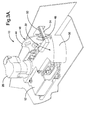
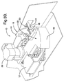
- Figures 3A and 3B also illustrate the situation, where the lever 44 defines a concave section having a side that forms the abutment 48.
- This particular lever 44 is part of the well-known door latch referred to above in the United States Patents 4,756,563 and 5,054,827. Accordingly, the lock pin 24 - when in the locked position --extends into the concave section to prevent pivoting of the lever 44 and to prevent motion transfer to the latching assembly 14.
- the lock pin 24 has an angled surface 50 conforming to the angle of the side forming the abutment 48.
- the lock pin 24 also has a radius 51 and a another angled surface 54 parallel to surface 50 to conform to the space defined in part by the enclosure 12 as shown in Figures 5A and 5B. If a person tries to pull the inside latch handle 18 while the child security lock is engaged, the surface 48 will abut the lock pin 24 along surface 50. The lock pin 24 is further backed by the enclosure 12. Thus, the lever 44 cannot pivot to translate motion to the element 46 and eventually to the latching assembly.
- the door latch 10 further includes a housing 56 for enclosing the motor assembly 26 and the linkage 30.
- the housing 56 defines an elongated opening 58 providing clearance for the lock pin 24 as it moves between the locked and unlocked positions.
- the housing 56 includes at least two detent indentations inside the housing (not shown).
- the housing 56 further includes features for guiding and supporting the rack 32 as it shuttles back and forth in response to the motor 27.
- One feature is a bumper 60 disposed adjacent the rack 32. ( Figure 4)
- the rack 32 has corresponding first and second limit arms 62 spaced apart from each other and extending away from the rack 32 in the perpendicular manner shown in Figure 4. These limit arms 62 extend on either side of the bumper 60 to limit the reciprocating movement of the rack 32.
- Another feature in the housing for guiding and supporting the rack is an elongated tongue or flange (not shown). This tongue or flange extends matingly into an elongated liner groove 64 in the rack 32.
- the linkage 30 includes a detent 66 engaging the detent indentations (not shown) in the housing 56.
- the detent 66 is moveable between the indentations.
- the detent 66 engages the housing's detent indentations.
- This arrangement of the detent 66 and the corresponding indentations provides sufficient holding force for maintaining the rack 32 - and therefore the lock pin 24 - in the locked or unlocked postion.
- the holding force can be overcome with the force of the motor 27, or with a force applied by a human finger.
- the lock pin 24 has a length specially sized so that it extends through a slot in the vehicle door 20 to allow for manual operation. This is shown best in Figures 1, 2, and 3.
- the entire power child security lock assembly 22, including the housing 56, may be viewed as a unit; and this entire unit can be fastened to the side of the existing door latch with fasteners as shown in Figures 3A and 3B.
- This assembly 22 was adapted from an earlier actuator assembly that was used to actuate various door systems including a deadbolt system.
- the earlier actuator assembly was altered for the present invention by adding the lock pin 24 to the end of the rack 32 in the manner shown, and by forming the elongated opening 58 in the housing 56.
- a person can remotely operate the motor 27 with a switch (not shown).
- the motor 27 will then drive the rack 32 - and thus the lock pin 24 - by means of the gear teeth on the motor gear 29, the pinion 36 and the rack itself.
Landscapes
- Health & Medical Sciences (AREA)
- Child & Adolescent Psychology (AREA)
- Lock And Its Accessories (AREA)
Abstract
A vehicle door latch (10) with a power child security lock
comprises an enclosure (12) and several components mounted on or in the
enclosure. First is a latching assembly (14) disposed in the enclosure and adapted
to move between an unlatched configuration and a latched configuration. There
is also an inside latch handle assembly (16) disposed adjacent the latching
assembly (14). The inside latch handle assembly (16) transfers motion to the
latching assembly in response to an actuator to move the latching assembly to the
unlatched configuration. A child security lock assembly (22) for the inside latch
handle assembly (16) includes a lock pin (24) that is moveable between a locked
position and an unlocked position. In the locked position, the lock pin (24) engages
the inside latch handle assembly (16) to prevent any motion transfer to the latching
assembly (14). In the unlocked position, the lock pin (24) disengages the inside
latch handle assembly (16) to allow motion transfer to the latching assembly (14).
The child security lock assembly (22) also includes a motor assembly (26) disposed
adjacent the lock pin (24), and a linkage (30) interconnecting the lock pin and the
motor assembly wherein the motor assembly controls movement of the lock pin.
Description
- The present invention relates to a vehicle door latch, and more particularly to a vehicle door latch having a child security mechanism.
- Vehicle manufacturers have concerned themselves with child security features on door latches, and especially rear door latches. Presently there are several types of child security locks for disabling the rear inside door latch handle of a vehicle.
- One type of security lock involves a hand-operated lever that pivots into and out of engagement with the door latch components. The purpose of the lever is to engage one or more of these components to block or arrest motion transfer along the motion transfer path between the rear inside door latch handle and the latching assembly that unlatches the rear door. In order to operate the lever, a person must open the rear door to access the lever, which is located adjacent the door latch.
- Another type of hand-activated system is a free-wheeling system. In such a system, some of the motion-transferring components in the latch's motion transfer path can switch into a free-wheeling or lost motion mode wherein they do not transfer motion from the inside latch handle to the latching assembly.
- These manually operated systems are effective; but they lack convenience. For example, the driver may want to activate the security lock while seated in the vehicle - perhaps even while driving. This is not possible without a power system for activating the lock, with a switch located near the driver seat.
- There are power security lock systems of the type shown in United States Patents 5,511,838 to Baughman et al; and 5,263,751 to Priest et al. These systems each involve an electro-mechanical assembly disposed in the motion transfer path between the inside latch handle and the latching assembly. But in both cases the electro-mechanical assembly is positioned in the middle of the door - mid-way between the latch handle and the latching assembly. Both systems involve establishing a free-wheeling junction along the motion transfer path between the inside latch handle and the latching assembly. Thus, when the lock is activated, the motion transfer path is broken, and the inside latch handle will simply free-wheel. These two power systems are effective, but they leave room for improvement in the area of simplicity and packaging. Both are complex assemblies involving several parts; and both involve installation in the middle of the door and remote from the latching assembly. This translates into higher labor and material costs, and possibly higher vehicle weight.
- The present invention is a comparatively compact and simple arrangement for providing a power child security lock for a vehicle door latch assembly.
- The present invention comprises an enclosure and several components mounted on or in the enclosure. First is a latching assembly disposed in the enclosure and adapted to move between an unlatched configuration and a latched configuration. There is also an inside latch handle assembly disposed adjacent the latching assembly for transferring motion to the latching assembly in response to an actuator to move the latching assembly to the unlatched configuration. A child security lock assembly for the inside latch handle assembly includes a lock pin. The lock pin is moveable between a locked position in which the lock pin engages the inside latch handle assembly to prevent any motion transfer to the latching assembly, and an unlocked position in which the lock pin disengages the inside latch handle assembly to allow motion transfer to the latching assembly. The child security lock assembly also includes a motor assembly disposed adjacent the lock pin, and a linkage interconnecting the lock pin and the motor assembly wherein the motor assembly controls movement of the lock pin.
- The present invention will now be described, by way of example, with reference to the accompanying drawings, in which:
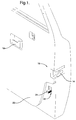
- Figure 1 is a perspective view of a vehicle door showing an inside latch handle, a latching assembly and a child security lock pin;
- Figure 2 is a bottom perspective view taken from outside the door showing a portion of the door and the latching assembly with the child security lock assembly;
- Figure 3A is a bottom perspective view similar to the view in Figure 2, but taken from an angle inside the door, showing the child security lock in the unlocked position;
- Figure 3B is a view similar to the view in Figure 3A showing the child security lock in the locked position;
- Figure 4 is a perspective view of the child security lock assembly with the housing removed to show the elements of the child security lock assembly;
- Figure 5A is a front view of the lock pin and portions of the latching assembly, with the lock pin in the unlocked configuration; and
- Figure 5B is a view similar to the view in Figure 5A showing the lock pin in the locked position.
-
- Referring to the Figures wherein like numerals indicate like or corresponding parts throughout the several views, a door latch assembly with a power child security lock is generally shown at 10.
- The
door latch 10 generally includes anenclosure 12 and several components disposed on or in the enclosure. Some of the components relate to the basic latching and unlatching functions. Other components relate to the power-operated child security lock. - First, a
latching assembly 14 is disposed in theenclosure 12 and is adapted to move between an unlatched configuration and a latched configuration. In other words, thelatching assembly 14 can move from one configuration to the other -- and back again. Thepresent latching assembly 14 is a fork bolt type of latching assembly as shown in the figures. Thelatching assembly 14 includes a fork bolt and certain other parts, although the exact number and arrangement of the parts is not critical to the invention. - An inside latch handle assembly, generally indicated at 16, is disposed adjacent the
latching assembly 14 for transferring motion to thelatching assembly 14 in response to an actuator to move the latching assembly to its unlatched configuration. The "actuator" is a general term that may include manual or power systems. For example, the term may include a person who grasps and pulls an inside latch handle 18 on thevehicle door 20. In such a case, there is some link (not shown) between theinside latch handle 18 and the insidelatch handle assembly 16 that is part of thesubject door latch 10. Alternatively, the "actuator" may be a power mechanism that effects unlatching through a motion-creating force. - These components of the door latch 10 - the ones relating to the latching and unlatching functions -- may assume many forms. The invention is not dependent on these components having any particular arrangement or form. Preferably, the
enclosure 12, thelatching assembly 14, and the insidelatch handle assembly 16 are a unit in the form of a basic door latch - in other words, a door latch without any child security lock assembly. Such a basic door latch assembly is well-known. It is shown in United States Patent 4,756,563 granted to Stephen L. Garwood and Jeffrey L. Konchan, and United States Patent 5,054,827 granted to Jeffrey L. Konchan and Jiri Paulik. The teachings of these patents are incorporated here by reference. - In addition to this basic door latch, there is also a child security lock assembly associated with the inside latch handle assembly, and generally indicated at 22. The child
security lock assembly 22 includes alock pin 24 moveable between two positions. Figures 5A and 5B illustrate the two positions. The first position (Figure 5B) is a locked position in which thelock pin 24 engages the insidelatch handle assembly 16 to block, arrest, freeze or otherwise prevent any motion transfer to thelatching assembly 14. The second position (Figure 5A) is an unlocked position in which thelock pin 24 disengages the insidelatch handle assembly 16 to allow motion transfer to thelatching assembly 14. Thus, the action of the childsecurity lock assembly 22 is to block out rather than to disengage, or free-wheel, or interrupt. - As shown in Figure 4, the child
security lock assembly 22 also includes amotor assembly 26 disposed adjacent thelock pin 24, and alinkage 30 interconnecting thelock pin 24 and themotor assembly 26 wherein the motor assembly controls movement of the lock pin. - The
motor assembly 26 includes anelectric motor 27, amotor shaft 28, and amotor gear 29 disposed on theshaft 28. Themotor 27 connects to some external power source (not shown) and a remote control (not shown). The remote control may be located in some convenient position - perhaps near the driver seat in the vehicle. - The
linkage 30 includes anelongated rack 32 having a first end and a second end, with a plurality ofrack teeth 34 disposed on the first end. Theteeth 34 extend along the first end as shown in Figure 4 for a few centimeters. - The
linkage 30 further includes apinion 36 interconnecting therack teeth 34 and themotor gear 29. Thepinion 36 includes two sets of circular gear teeth that are concentrically arranged. A portion of thepinion 36 is cut away in Figure 4 to illustrate this particular arrangement. An outer set ofgear teeth 37 engages the teeth of themotor gear 29. An inner set ofgear teeth 39 engages therack teeth 34. Other arrangements are possible. Therack 32, thepinion 36, and themotor gear 29 are all made from a suitable plastic material. - The
lock pin 24 is disposed on the second end of therack 32 in a manner perpendicular to the rack. Thelock pin 24 extends away from the elongated part of therack 32 for a distance of several centimeters. In the preferred case, thelock pin 24 is molded as part of therack 32 to create an "L" shaped member. Aspacer section 38 supports the lock pin 24 a predetermined distance above the top of therack 32 as shown in Figure 4. Agusset 40 extends between therack 32 and thelock pin 24 to support the lock pin. - The inside
latch handle assembly 16 includes at least first and secondmotion transferring elements motion transferring element 44 transfers motion to the secondmotion transferring element 46, and the secondmotion transferring element 46 transfers motion to the latchingassembly 14. The manner in which this may be accomplished can vary. Examples are shown in United States Patents 4,756,563 and 5,054,827. One of the motion transfer elements - in this case the first motion transferring element 44 - is a lever pivotally mounted on theenclosure 12 for transferring motion - eventually, by way of other parts -- to the latchingassembly 14. Thelever 44 defines some sort ofabutment 48 for thelock pin 24 to abut when the lock pin is in the locked position so that the lock pin can prevent thelever 44 from transferring any motion to the latchingassembly 14. Figures 5A and 5B illustrate the situation best. Figures 3A and 3B also illustrate the situation, where thelever 44 defines a concave section having a side that forms theabutment 48. Thisparticular lever 44 is part of the well-known door latch referred to above in the United States Patents 4,756,563 and 5,054,827. Accordingly, the lock pin 24 - when in the locked position --extends into the concave section to prevent pivoting of thelever 44 and to prevent motion transfer to the latchingassembly 14. - The
lock pin 24 has an angledsurface 50 conforming to the angle of the side forming theabutment 48. Thelock pin 24 also has aradius 51 and a anotherangled surface 54 parallel to surface 50 to conform to the space defined in part by theenclosure 12 as shown in Figures 5A and 5B. If a person tries to pull the inside latch handle 18 while the child security lock is engaged, thesurface 48 will abut thelock pin 24 alongsurface 50. Thelock pin 24 is further backed by theenclosure 12. Thus, thelever 44 cannot pivot to translate motion to theelement 46 and eventually to the latching assembly. - The
door latch 10 further includes ahousing 56 for enclosing themotor assembly 26 and thelinkage 30. Thehousing 56 defines anelongated opening 58 providing clearance for thelock pin 24 as it moves between the locked and unlocked positions. Thehousing 56 includes at least two detent indentations inside the housing (not shown). Thehousing 56 further includes features for guiding and supporting therack 32 as it shuttles back and forth in response to themotor 27. One feature is abumper 60 disposed adjacent therack 32. (Figure 4) Therack 32 has corresponding first andsecond limit arms 62 spaced apart from each other and extending away from therack 32 in the perpendicular manner shown in Figure 4. These limitarms 62 extend on either side of thebumper 60 to limit the reciprocating movement of therack 32. Another feature in the housing for guiding and supporting the rack is an elongated tongue or flange (not shown). This tongue or flange extends matingly into anelongated liner groove 64 in therack 32. - The
linkage 30 includes adetent 66 engaging the detent indentations (not shown) in thehousing 56. Thedetent 66 is moveable between the indentations. When thehousing 56 is assembled over thelinkage 30, thedetent 66 engages the housing's detent indentations. This arrangement of thedetent 66 and the corresponding indentations provides sufficient holding force for maintaining the rack 32 - and therefore the lock pin 24 - in the locked or unlocked postion. The holding force can be overcome with the force of themotor 27, or with a force applied by a human finger. - The
lock pin 24 has a length specially sized so that it extends through a slot in thevehicle door 20 to allow for manual operation. This is shown best in Figures 1, 2, and 3. - The entire power child
security lock assembly 22, including thehousing 56, may be viewed as a unit; and this entire unit can be fastened to the side of the existing door latch with fasteners as shown in Figures 3A and 3B. Thisassembly 22 was adapted from an earlier actuator assembly that was used to actuate various door systems including a deadbolt system. The earlier actuator assembly was altered for the present invention by adding thelock pin 24 to the end of therack 32 in the manner shown, and by forming theelongated opening 58 in thehousing 56. - In operation, one can operate the
child security lock 22 either manually or with power. In the case of manual operation, one can simply open thevehicle door 20 and move thelock pin 24 upwardly. As shown in Figures 5A and 5B, this will place thelock pin 24 adjacent thelever 44 of the insidelatch handle assembly 16, and block any motion transfer from thislever 44 to parts such as 46 that will in turn transfer motion to the latchingassembly 14. - In the case of power operation, a person can remotely operate the
motor 27 with a switch (not shown). Themotor 27 will then drive the rack 32 - and thus the lock pin 24 - by means of the gear teeth on themotor gear 29, thepinion 36 and the rack itself.
Claims (12)
- A door latch for mounting on a vehicle door comprising:an enclosure;a latching assembly disposed in the enclosure and adapted to move between an unlatched configuration and a latched configuration,an inside latch handle assembly disposed adjacent the latching assembly for transferring motion to the latching assembly in response to an actuator to move the latching assembly to the unlatched configuration;a child security lock assembly for the inside latch handle assembly, the child security lock assembly includinga lock pin moveable between a locked position in which the lock pin engages the inside latch handle assembly to prevent any motion transfer to the latching assembly, and an unlocked position in which the lock pin disengages the inside latch handle assembly to allow motion transfer to the latching assembly,a motor assembly disposed adjacent the lock pin, anda linkage interconnecting the lock pin and the motor assembly wherein the motor assembly controls movement of the lock pin.
- The door latch of claim 1 wherein the motor assembly includes a motor, a motor shaft and a motor gear disposed on the shaft.
- The door latch of claim 2 wherein the linkage includes a rack having a first end and a second end, with a plurality of rack teeth disposed on the first end.
- The door latch of claim 3 wherein the linkage includes a pinion interconnecting the rack teeth and the motor gear.
- The door latch of claim 4 wherein the lock pin is disposed on the second end of the rack.
- The door latch of claim 5 wherein the lock pin is disposed perpendicular to the rack.
- The door latch of claim 6 wherein the inside latch handle assembly includes at least first and second motion transferring elements disposed in series wherein the first motion transferring element transfers motion to the second motion transferring element, and the second motion transferring element transfers motion to the latching assembly.
- The door latch of claim 7 wherein one of the motion transfer elements is a lever pivotally mounted on the enclosure for transferring motion to the latching assembly.
- The door latch of claim 8 wherein the lever defines an abutment.
- The door latch of claim 9 wherein the lock pin abuts the abutment when in the locked position to prevent pivoting of the lever and to prevent motion transfer to the latching assembly.
- The door latch of claim 10 further including a housing enclosing the motor assembly and the linkage, the housing defining an elongated opening providing clearance for the lock pin.
- The door latch of claim 11 wherein the linkage includes a detent engaging the housing.
Applications Claiming Priority (2)
| Application Number | Priority Date | Filing Date | Title |
|---|---|---|---|
| US329519 | 1999-06-10 | ||
| US09/329,519 US6199923B1 (en) | 1999-06-10 | 1999-06-10 | Vehicle door latch |
Publications (1)
| Publication Number | Publication Date |
|---|---|
| EP1059407A2 true EP1059407A2 (en) | 2000-12-13 |
Family
ID=23285799
Family Applications (1)
| Application Number | Title | Priority Date | Filing Date |
|---|---|---|---|
| EP00201679A Withdrawn EP1059407A2 (en) | 1999-06-10 | 2000-05-11 | Vehicle door latch |
Country Status (2)
| Country | Link |
|---|---|
| US (1) | US6199923B1 (en) |
| EP (1) | EP1059407A2 (en) |
Cited By (2)
| Publication number | Priority date | Publication date | Assignee | Title |
|---|---|---|---|---|
| GB2412694A (en) * | 2004-03-29 | 2005-10-05 | Tri Mark Corp | Lock system comprising a latch with a movable element obstructing the latch release actuator |
| EP3029230A1 (en) * | 2014-12-03 | 2016-06-08 | Mitsui Kinzoku ACT Corporation | Relay mechanism of vehicle sliding door |
Families Citing this family (19)
| Publication number | Priority date | Publication date | Assignee | Title |
|---|---|---|---|---|
| GB2332235B (en) * | 1997-12-12 | 2001-12-05 | Meritor Light Vehicle Sys Ltd | Vehicle door latch mechanism |
| DE19843422C5 (en) * | 1998-09-22 | 2008-03-06 | Bayerische Motoren Werke Ag | Door lock of a motor vehicle |
| EP1296844B1 (en) * | 2000-07-03 | 2008-05-28 | Stoneridge Control Devices, Inc. | Fuel door lock actuator |
| DE10128668A1 (en) * | 2001-06-13 | 2003-01-09 | Kiekert Ag | emergency locking |
| KR100387750B1 (en) * | 2001-07-12 | 2003-06-18 | 동아특수정밀 주식회사 | An automatic open and shut apparatus for a door of the passenger car |
| US7088283B2 (en) * | 2001-07-24 | 2006-08-08 | Funai Electric Co., Ltd. | Player with a remote controller, remote controller and player |
| JP3906341B2 (en) * | 2001-09-18 | 2007-04-18 | 三井金属鉱業株式会社 | Gate lock device for vehicle |
| GB0122634D0 (en) * | 2001-09-20 | 2001-11-14 | Meritor Light Vehicle Sys Ltd | Door release and engagement mechanism |
| GB0207526D0 (en) * | 2002-04-02 | 2002-05-08 | Meritor Light Vehicle Sys Ltd | Control system for a vehicle door latch |
| US6811193B2 (en) * | 2002-07-10 | 2004-11-02 | Delphi Technologies, Inc. | Quiet vehicle door latch |
| US6874830B2 (en) * | 2002-09-30 | 2005-04-05 | Rutherford Controlls Int'l Corp. | Electric strike assembly |
| GB0309266D0 (en) * | 2003-04-24 | 2003-06-04 | Arvinmeritor Light Vehicle Sys | A lock mechanism |
| WO2006099730A1 (en) * | 2005-03-23 | 2006-09-28 | Magna Closures Inc. | Global side door latch |
| US9080354B2 (en) | 2011-06-15 | 2015-07-14 | Ford Global Technologies, Llc | Logic-based sliding door interlock |
| JP6450991B2 (en) * | 2014-10-29 | 2019-01-16 | 三井金属アクト株式会社 | Vehicle door latch device |
| JP6988412B2 (en) * | 2017-12-01 | 2022-01-05 | トヨタ自動車株式会社 | Sliding door device for vehicles |
| CN111101778B (en) * | 2018-10-25 | 2025-07-11 | 比亚迪股份有限公司 | Door locks and vehicles |
| US20200224464A1 (en) * | 2019-01-10 | 2020-07-16 | Magna Closures Inc. | Smart latch assembly with actuator module |
| KR102633869B1 (en) * | 2019-08-19 | 2024-02-05 | 현대자동차 주식회사 | Power child lock device |
Citations (2)
| Publication number | Priority date | Publication date | Assignee | Title |
|---|---|---|---|---|
| US5263751A (en) | 1992-11-16 | 1993-11-23 | General Motors Corporation | Door latch actuator |
| US5511838A (en) | 1994-02-14 | 1996-04-30 | General Motors Corporation | Remote latch release disabling device |
Family Cites Families (9)
| Publication number | Priority date | Publication date | Assignee | Title |
|---|---|---|---|---|
| US3111339A (en) * | 1960-09-15 | 1963-11-19 | American Motors Corp | Vehicle door lock |
| US3098671A (en) * | 1961-03-27 | 1963-07-23 | Wilmot Breeden Ltd | Vehicle door latches |
| US4875723A (en) * | 1988-03-03 | 1989-10-24 | General Motors Corporation | Closure latch |
| DE8809256U1 (en) * | 1988-07-20 | 1988-09-22 | Kiekert GmbH & Co KG, 5628 Heiligenhaus | Motor vehicle door lock with lock housed in the motor vehicle door and child safety lock |
| US4969673A (en) * | 1989-10-16 | 1990-11-13 | General Motors Corporation | Door latch with block-out type child safety feature |
| JP2782488B2 (en) * | 1992-08-24 | 1998-07-30 | 三井金属鉱業株式会社 | Super lock device for vehicles |
| US5537848A (en) * | 1994-06-27 | 1996-07-23 | General Motors Corporation | Deadbolt locking system |
| DE19530726C5 (en) * | 1995-08-18 | 2009-07-02 | Kiekert Ag | Central locking system with identical motor vehicle door locks |
| US5715713A (en) * | 1996-01-11 | 1998-02-10 | General Motors Corporation | Door latch locking actuator assembly |
-
1999
- 1999-06-10 US US09/329,519 patent/US6199923B1/en not_active Expired - Fee Related
-
2000
- 2000-05-11 EP EP00201679A patent/EP1059407A2/en not_active Withdrawn
Patent Citations (2)
| Publication number | Priority date | Publication date | Assignee | Title |
|---|---|---|---|---|
| US5263751A (en) | 1992-11-16 | 1993-11-23 | General Motors Corporation | Door latch actuator |
| US5511838A (en) | 1994-02-14 | 1996-04-30 | General Motors Corporation | Remote latch release disabling device |
Cited By (4)
| Publication number | Priority date | Publication date | Assignee | Title |
|---|---|---|---|---|
| GB2412694A (en) * | 2004-03-29 | 2005-10-05 | Tri Mark Corp | Lock system comprising a latch with a movable element obstructing the latch release actuator |
| US7234329B2 (en) | 2004-03-29 | 2007-06-26 | Tri/Mark Corporation | Lock system for movable closure element |
| GB2412694B (en) * | 2004-03-29 | 2009-08-26 | Tri Mark Corp | Lock system for movable closure element |
| EP3029230A1 (en) * | 2014-12-03 | 2016-06-08 | Mitsui Kinzoku ACT Corporation | Relay mechanism of vehicle sliding door |
Also Published As
| Publication number | Publication date |
|---|---|
| US6199923B1 (en) | 2001-03-13 |
Similar Documents
| Publication | Publication Date | Title |
|---|---|---|
| US6199923B1 (en) | Vehicle door latch | |
| US6406075B1 (en) | Latch handle assembly | |
| US6158788A (en) | Door locking device | |
| EP0775791B1 (en) | Vehicle door lock actuator | |
| EP0164756B1 (en) | Door handle device unlockable from indoor side | |
| CA2576211C (en) | Power release double-locking latch | |
| EP0775793B1 (en) | Vehicle door lock actuator | |
| EP0745746B1 (en) | Latch cinching mechanism and latch assembly | |
| EP0693605B1 (en) | Deadbolt locking system | |
| CN1550629B (en) | A lock mechanism | |
| US8382168B2 (en) | Magnetic latch mechanism | |
| EP1097283B1 (en) | Vehicle door latch | |
| US6045168A (en) | Door latch with improved double lock | |
| US6655179B2 (en) | Automotive door lock assembly | |
| EP0379273B1 (en) | Vehicle door locking system | |
| EP0887500B1 (en) | Vehicle door latch | |
| GB2334297A (en) | Vehicle door lock with controlled pawl locking mechanism | |
| JP3338950B2 (en) | Door lock device | |
| EP0892136A1 (en) | Vehicle door securing mechanism | |
| EP0770748A1 (en) | Vehicle door lock actuator | |
| EP0021743A1 (en) | Lock for a tiltable truck cab and vehicles including such locks | |
| JP3364566B2 (en) | Relay mechanism for sliding doors for vehicles |
Legal Events
| Date | Code | Title | Description |
|---|---|---|---|
| PUAI | Public reference made under article 153(3) epc to a published international application that has entered the european phase |
Free format text: ORIGINAL CODE: 0009012 |
|
| AK | Designated contracting states |
Kind code of ref document: A2 Designated state(s): AT BE CH CY DE DK ES FI FR GB GR IE IT LI LU MC NL PT SE |
|
| AX | Request for extension of the european patent |
Free format text: AL;LT;LV;MK;RO;SI |
|
| STAA | Information on the status of an ep patent application or granted ep patent |
Free format text: STATUS: THE APPLICATION IS DEEMED TO BE WITHDRAWN |
|
| 18D | Application deemed to be withdrawn |
Effective date: 20021203 |