EP1059369A1 - Method and apparatus for degreasing steel strip - Google Patents

Method and apparatus for degreasing steel strip Download PDF

Info

Publication number
EP1059369A1
EP1059369A1 EP00112440A EP00112440A EP1059369A1 EP 1059369 A1 EP1059369 A1 EP 1059369A1 EP 00112440 A EP00112440 A EP 00112440A EP 00112440 A EP00112440 A EP 00112440A EP 1059369 A1 EP1059369 A1 EP 1059369A1
Authority
EP
European Patent Office
Prior art keywords
steel strip
washing apparatus
degreasing
electrolytic
electrolytic washing
Prior art date
Legal status (The legal status is an assumption and is not a legal conclusion. Google has not performed a legal analysis and makes no representation as to the accuracy of the status listed.)
Withdrawn
Application number
EP00112440A
Other languages
German (de)
French (fr)
Inventor
Kazuya c/o Kawasaki Steel Corporation Nishizato
Seiichi c/o Kawasaki Steel Corporation Takahashi
Hidetoshi c/o Kawasaki Steel Corporation Takeda
Setsuo c/o Hotani Co. Ltd. Hotani
Current Assignee (The listed assignees may be inaccurate. Google has not performed a legal analysis and makes no representation or warranty as to the accuracy of the list.)
JFE Steel Corp
Hotani Co Ltd
Original Assignee
Hotani Co Ltd
Kawasaki Steel Corp
Priority date (The priority date is an assumption and is not a legal conclusion. Google has not performed a legal analysis and makes no representation as to the accuracy of the date listed.)
Filing date
Publication date
Application filed by Hotani Co Ltd, Kawasaki Steel Corp filed Critical Hotani Co Ltd
Publication of EP1059369A1 publication Critical patent/EP1059369A1/en
Withdrawn legal-status Critical Current

Links

Images

Classifications

    • CCHEMISTRY; METALLURGY
    • C25ELECTROLYTIC OR ELECTROPHORETIC PROCESSES; APPARATUS THEREFOR
    • C25FPROCESSES FOR THE ELECTROLYTIC REMOVAL OF MATERIALS FROM OBJECTS; APPARATUS THEREFOR
    • C25F1/00Electrolytic cleaning, degreasing, pickling or descaling
    • CCHEMISTRY; METALLURGY
    • C25ELECTROLYTIC OR ELECTROPHORETIC PROCESSES; APPARATUS THEREFOR
    • C25FPROCESSES FOR THE ELECTROLYTIC REMOVAL OF MATERIALS FROM OBJECTS; APPARATUS THEREFOR
    • C25F7/00Constructional parts, or assemblies thereof, of cells for electrolytic removal of material from objects; Servicing or operating

Definitions

  • the present invention relates to an electrolytic washing apparatus and a steel strip degreasing method using the apparatus.
  • the present invention also relates to a method and apparatus for degreasing steel strips making use of electrolytic washing to remove rolling oil and the like deposited on cold-rolled steel strips.
  • the inventors have found, in the investigation of a mechanism of electrolytic washing in a degreasing apparatus, that electrolytic washing can be carried out with a small amount of electric power when the relationship between electricity density and current density is maintained within a proper range.
  • the wettability was determined by applying water to a specimen inclined at 45° and by visually observing the proportion of the area which was thereby wetted.
  • the amount of the remaining oily substance was determined by dipping a specimen into an organic solvent, and the decrease in weight of the specimen, which was determined by subtracting the weight of the specimen after it was dipped from the weight thereof before it was dipped, was considered to correspond to the amount of the remaining oily substance (mg/m 2 ). It was determined that degreasing could be sufficiently carried out when the thus determined wettability was about 90% or more and the amount of the remaining oily substance was about 3 mg/m 2 or less.
  • Fig. 4 shows the result of the determination. Degreasing can be satisfactorily carried out within the hatched region in Fig. 4.
  • the present invention thus provides a steel strip degreasing method including a process in which electrolytic washing is carried out under the following conditions.
  • Y ⁇ 0.01 ⁇ X -2 when X ⁇ 0.12 Y ⁇ 0.7 when 0.12 ⁇ X ⁇ 1.0
  • X represents the electricity density (C/dm 2 )
  • Y represents the current density (A/dm 2 ).
  • the present invention also provides an electrolytic washing apparatus having electrodes which confront each other across a steel strip located therebetween, wherein each electrode has a length L (mm) of about 500 to about 0.5 mm in the traveling direction of a steel strip and satisfies the condition of the following formula. 500 ⁇ (S ⁇ X)/(60 ⁇ Y ⁇ C) ⁇ L ⁇ 1100 ⁇ (S ⁇ X)/(60 ⁇ Y ⁇ C), where
  • the present invention provides a steel strip degreasing apparatus including any of the above electrolytic washing apparatuses.
  • the steel strip degreasing apparatus further include at least one device selected from a brush washing apparatus and a high pressure water washing apparatus in addition to any of the above electrolytic washing apparatuses. It is especially preferred that the selected washing apparatus be disposed in a process downstream of the electrolytic washing apparatus.
  • Fig. 1 is a schematic view showing an example of a degreasing apparatus using the dipping type electrolytic washing apparatus of the present invention.
  • the arrow in the figure shows the traveling direction of a steel strip 1.
  • the steel strip 1 is transported to the dipping type electrolytic washing apparatus 7 through pinch rolls 2.
  • Electrodes 8 and sink rolls 4 are disposed in the electrolytic tank of the dipping type electrolytic washing apparatus 7.
  • a pair or two or more pairs of the electrodes 8 are disposed above and below the steel strip 1.
  • the apparatus of the present invention is compared with the conventional apparatus shown in Fig. 6, since it does not need the brush washing apparatus 5 and the alkali dipping tank 3 which are located upstream of the dipping type electrolytic washing apparatus 7, it can carry out degreasing in a simple process as compared with the conventional apparatus.
  • an electrolytic washing efficiency can be improved as well as a time necessary for electrolytic washing can be shortened and power consumption can be reduced. Furthermore, the length (L 1 ) of the electrodes 8 can be shortened by the improvement of the washing efficiency.

Landscapes

  • Chemical & Material Sciences (AREA)
  • Engineering & Computer Science (AREA)
  • Chemical Kinetics & Catalysis (AREA)
  • Electrochemistry (AREA)
  • Materials Engineering (AREA)
  • Metallurgy (AREA)
  • Organic Chemistry (AREA)
  • Cleaning And De-Greasing Of Metallic Materials By Chemical Methods (AREA)

Abstract

A steel strip is degreased with low power consumption by subjecting the steel strip to electrolytic washing in a degreasing apparatus including an electrolytic washing apparatus in which electrodes confront each other across the steel strip located therebetween, and charge density and current density are maintained within a predetermined range. There is also provided a simple steel strip degreasing apparatus which is especially suitable for the method.

Description

BACKGROUND OF THE INVENTION 1. Field of the Invention
The present invention relates to an electrolytic washing apparatus and a steel strip degreasing method using the apparatus. The present invention also relates to a method and apparatus for degreasing steel strips making use of electrolytic washing to remove rolling oil and the like deposited on cold-rolled steel strips.
2. Description of the Related Art
In general, cold-rolled steel strips are degreased by being dipped into an alkali solution or by being subjected to electrolytic washing as well as by washing with brushes (hereinafter, referred to as brush washing) and washing with high pressure water (hereinafter, referred to as high pressure water washing) which are carried out together with the above dipping and electrolytic washing. A dipping type electrolytic washing apparatus and a spray type electrolytic washing apparatus are available as an apparatus for carrying out electrolytic washing. In the dipping type electrolytic washing apparatus, electrolytic washing is carried out using electrodes disposed above and below a steel strip in an electrolytic tank. In the spray type electrolytic washing apparatus, electrolytic washing is carried out by spraying an electrolytic solution onto a steel strip from spray nozzles, which are disposed above and below the steel strip and have electrodes mounted thereon.
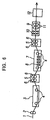
Fig. 6 is a schematic view showing a conventional steel strip degreasing apparatus. The arrow in the figure shows the traveling direction of a steel strip. The steel strip 1 is washed with brush rolls 6 after it passes through an alkali dipping tank 3. The steel strip 1 is again subjected to electrolytic washing in an electrolytic washing apparatus 7. Then, after the steel strip 1 is washed with brush rolls 6 again, it passes through a rinse apparatus 9 and a dryer 12, whereby a series of degreasing treatments are carried out.
For example, Japanese Unexamined Patent Application Publication No. 8-174042 discloses a degreasing method and apparatus for carrying out degreasing in a non-contact fashion using dipping type electrolytic washing and high pressure water washing. Japanese Unexamined Patent Application Publication No. 10-237700 discloses another degreasing method and apparatus for carrying out degreasing by spray type electrolytic washing, in which a voltage is imposed on a pair of spray nozzles disposed above and below a steel strip, and by brush washing.
Since a steel strip is generally vibrated also in the thickness direction thereof while it travels, when dipping type electrolytic washing is employed as shown in Japanese Unexamined Patent Application Publication No. 8-174042, the steel strip in travel must be prevented from coming into contact with, or colliding against, the electrodes. For this purpose, the electrodes of an electrolytic washing apparatus must be spaced apart from a steel strip. In particular, the conventional electrolytic washing has a problem in that such a large distance is necessary between the electrodes and the steel strip, that a large amount of electric power is required to carry out electrolytic washing.
Furthermore, the series of steps is complicated in the conventional degreasing treatment, and therefore conventional degreasing apparatus is undesirably large and expensive.
On the other hand, in Japanese Unexamined Patent Application Publication No. 10-237700, the steel strip is prevented from coming into contact with electrodes by virtue of being supported by a high liquid pressure from spray nozzles which also serve as the electrodes; however, this document teaches no technique for properly calculating line conditions to be applied, that is, values to be set to electrodes with respect to line speed: S, thickness of steel strip: TS, width of steel strip: WS, and other parameters such as current: I, length of nozzle: L1, width of nozzle: W, and so on. Accordingly, the steel strip is still insufficiently washed due to inappropriate setting of the electrode parameters. That is, it is difficult to provide sufficient degreasing conditions at all times.
An object of the present invention, which was made to solve the above problems, is to provide a steel strip degreasing method and a steel strip degreasing apparatus capable of performing excellent washing, the degreasing apparatus being arranged such that it can be constructed at a low cost, operating cost can be reduced, that is, electric power required for carrying out electrolytic washing can be reduced, and proper electrolytic conditions can be easily set in accordance with a variety of operating conditions.
SUMMARY OF THE INVENTION
The inventors have completed the present invention by finding, in the investigation of a mechanism of electrolytic washing in a degreasing apparatus, that electrolytic washing can be carried out with a small amount of electric power when the relationship between electricity density and current density is maintained within a proper range.
That is, according to the present invention, there is provided a method of degreasing a steel strip which includes the step of carrying out electrolytic washing under the following condition of electricity density X (C/dm2) and current density Y (A/dm2). Y ≥ 0.01 × X-2 when X ≤ 0.12 Y ≥ 0.7 when 0.12 < X ≤ 1.0
It is preferable in the degreasing method that at least one technique selected from brush washing and high pressure water washing be carried out in another stage of said electrolytic washing.
According to the present invention, there is provided an electrolytic washing apparatus which includes electrodes which confront each other across a steel strip located therebetween, have a length L (mm) of 500 to 0.5 mm in the traveling direction of the steel strip and satisfy the condition of the following formula. 500 × (S × X)/(60 × Y × C) ≤ L ≤ 1100 × (S × X)/(60 × Y × C), where
  • S: linear speed (m/min) of steel strip;
  • X: electricity density (C/dm2);
  • Y: current density (A/dm2); and
  • C: number of electrode pairs.
  • It is preferable that the electrolytic washing apparatus be a dipping type electrolytic washing apparatus having electrodes whose length L is 500 to 10 mm or a spray type electrolytic washing apparatus having electrodes whose length L is 50 to 0.5 mm.
    Further, according to the present invention, there is provided a steel strip degreasing apparatus including any of the above electrolytic washing apparatuses.
    It is preferable that the steel strip degreasing apparatus includes at least one section selected from a brush washing apparatus and a high pressure water washing apparatus, in addition to any of the electrolytic washing apparatuses.
    Furthermore, in the present invention, there is provided a method in which any of the above electrolytic washing apparatuses and any of the above steel strip degreasing apparatuses are used and any of the above steel strip degreasing methods is carried out.
    BRIEF DESCRIPTION OF THE DRAWINGS
  • Fig. 1 is a schematic view showing an example of a degreasing apparatus using a dipping type electrolytic washing apparatus of the present invention;
  • Fig. 2 is a schematic view showing an example of a degreasing apparatus using the dipping type electrolytic washing apparatus of the present invention;
  • Fig. 3 is a schematic view showing an example of a degreasing apparatus using a spray type electrolytic washing apparatus of the present invention;
  • Fig. 4 is a graph showing the relationship among electricity density, current density and degreasing state;
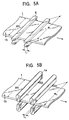
  • Figs. 5A and 5B are schematic views showing a steel strip, electrodes and a size of a slit nozzle, wherein Fig. 5A shows electrodes of the dipping type electrolytic washing apparatus and Fig. 5B shows the slit nozzles of a spray type electrolytic washing apparatus; and
  • Fig. 6 is a schematic view showing an example of a degreasing apparatus using a conventional dipping type electrolytic washing apparatus.
  • DESCRIPTION OF THE PREFERRED EMBODIMENT
    The inventors have found, in the investigation of a mechanism of electrolytic washing in a degreasing apparatus, that electrolytic washing can be carried out with a small amount of electric power when the relationship between electricity density and current density is maintained within a proper range.
    The inventors carried out electrolytic washing of steel strips with various electricity densities and various current densities. After a series of degreasing treatments were finished, the inventors determined whether degreasing was possible or not by examining wettability, an amount of a remaining oily substance and the like as to the oily substance on the surfaces of the steel strips.
    The wettability was determined by applying water to a specimen inclined at 45° and by visually observing the proportion of the area which was thereby wetted. The amount of the remaining oily substance was determined by dipping a specimen into an organic solvent, and the decrease in weight of the specimen, which was determined by subtracting the weight of the specimen after it was dipped from the weight thereof before it was dipped, was considered to correspond to the amount of the remaining oily substance (mg/m2). It was determined that degreasing could be sufficiently carried out when the thus determined wettability was about 90% or more and the amount of the remaining oily substance was about 3 mg/m2 or less. Fig. 4 shows the result of the determination. Degreasing can be satisfactorily carried out within the hatched region in Fig. 4.
    When the current density was less than 0.7A/dm2, degreasing was carried out insufficiently because an oily substance remained on the surfaces of a steel strip. Further, when the electricity density exceeded 1.0 C/dm2, electric power was consumed in a large amount. It can be found that even if the electricity density is 1.0 C/dm2 or less, degreasing can be sufficiently carried out when the relationship between the electricity density and the current density is maintained within a proper range.
    The present invention thus provides a steel strip degreasing method including a process in which electrolytic washing is carried out under the following conditions. Y ≥ 0.01 × X-2 when X ≤ 0.12 Y ≥ 0.7 when 0.12 < X ≤ 1.0 where, X represents the electricity density (C/dm2) and Y represents the current density (A/dm2).
    Note that while an upper limit of the electricity density X is about 1.0 C/dm2, it is preferably set to about 0.5 C/dm2 or less because a quantity of electricity is somewhat increased within the range of 0.5 < X (C/dm2) ≤ 1.0. Further, while an upper limit of the current density is not particularly limited within the range of the electricity density, it is preferably set to about 500 (A/dm2) and more preferably to about 200 (A/dm2). This is because there is a possibility that excessive current density might reduce life span of the electrode.
    Further, in the degreasing method, it is preferable that at least one technique selected from brush washing and high pressure water washing is carried out in another stage of the electrolytic washing. At that time, it is especially preferred that the selected washing be carried out in a process downstream of the electrolytic washing.
    The high pressure water washing is preferably carried out at a pressure of 10 to 200 kg/cm2 and more preferably at a pressure of 20 to 30 kg/cm2. This is because when the pressure is less than 10 kg/cm2, there is a possibility that the pressure of the water is insufficient, whereas when the pressure exceeds 200 kg/cm2, there is a possibility that a steel strip is damaged.
    Needless to say, the present invention does not exclude jobs other than those carried out in the electrolytic washing process, the brush washing process and the high pressure water washing process. Exemplified as these jobs are, for example, a job for operating devices relating to the connection of facilities such as rolls and the like, a drying job, a winding job and the like.
    The present invention also provides an electrolytic washing apparatus having electrodes which confront each other across a steel strip located therebetween, wherein each electrode has a length L (mm) of about 500 to about 0.5 mm in the traveling direction of a steel strip and satisfies the condition of the following formula. 500 × (S × X)/(60 × Y × C) ≤ L ≤ 1100 × (S × X)/(60 × Y × C), where
  • S: line speed (m/min) of steel strip;
  • X: electricity density (C/dm2);
  • Y: current density (A/dm2); and
  • C: number of electrode pairs.
  • Note that "to confront across the steel strip" means a state in which the electrodes confront each other without being in contact with the steel strip located therebetween and a direction in which they confront each other is not particularly limited. That is, while they may confront each other in a right and left direction or obliquely, they ordinarily confront each other vertically, which is to say perpendicular to the length of the strip.
    Note that it is preferable that the electrolytic washing apparatus be a dipping type electrolytic washing apparatus having electrodes whose length (L1) is about 500 to about 10 mm. One reason why the length of the electrodes of the dipping type electrolytic washing apparatus is set to the above range is that when the electrodes are too short, they may be overheated by the occurrence of current concentration, whereas too long electrodes are uneconomical. It is especially preferred that the length of the electrodes be about 100 to about 20 mm.
    It is also preferred that the electrolytic washing apparatus be a spray type electrolytic washing apparatus having electrodes whose length (L2) is about 50 to about 0.5 mm. One reason why the length of the electrodes of the spray type electrolytic washing apparatus is set to the above range is that when the electrodes are too short, they become clogged by an electrolytic solution, whereas too long electrodes are uneconomical because their capacity is increased. It is especially preferred that the length of the electrodes be 10 to 1 mm.
    In the present invention, it is preferable that the electrolytic washing apparatus be the dipping type electrolytic washing apparatus or the spray type electrolytic washing apparatus as described above. However, "the length L (of the electrodes) in the traveling direction of a steel strip" is denoted by L1 in the dipping type electrolytic washing apparatus and by L2 in the spray type electrolytic washing apparatus to discriminate their lengths in the former apparatus and in the latter apparatus. This is because, in the dipping type electrolytic washing apparatus, an electric effect can be evaluated by the length L1 of the electrodes as shown in Fig. 5A because the electric effect is influenced by the area of the electrodes themselves. On the other hand, in the spray type electrolytic washing apparatus, an electric effect must be evaluated using the length L2 of the slits in the traveling direction of the steel strip as the length L of the electrodes as shown in Fig. 5B. This is because that the electric effect is influenced by the area of the slits because the electrodes are not dipped in an electrolytic solution and energized through the electrolytic solution sprayed from the slits thereof.
    Further, the present invention provides a steel strip degreasing apparatus including any of the above electrolytic washing apparatuses. Note that it is preferable that the steel strip degreasing apparatus further include at least one device selected from a brush washing apparatus and a high pressure water washing apparatus in addition to any of the above electrolytic washing apparatuses. It is especially preferred that the selected washing apparatus be disposed in a process downstream of the electrolytic washing apparatus.
    Note that the present application does not exclude apparatuses other than the electrolytic washing apparatus and furthermore the brush washing apparatus and the high pressure water washing apparatus. Exemplified as such other apparatuses are, for example, connecting devices such as rolls interposed therebetween and further a drying apparatus, a winder and the like.
    Furthermore, the present invention employs any of the electrolytic washing apparatus and the steel strip degreasing apparatus and carries out any of the above steel strip degreasing methods.
    Fig. 1 is a schematic view showing an example of a degreasing apparatus using the dipping type electrolytic washing apparatus of the present invention. The arrow in the figure shows the traveling direction of a steel strip 1. First, the steel strip 1 is transported to the dipping type electrolytic washing apparatus 7 through pinch rolls 2. Electrodes 8 and sink rolls 4 are disposed in the electrolytic tank of the dipping type electrolytic washing apparatus 7. A pair or two or more pairs of the electrodes 8 are disposed above and below the steel strip 1.
    The steel strip 1, which has been washed in the dipping type electrolytic washing apparatus 7, is subjected to brush washing by the brush rolls 6 disposed in a brush washing apparatus 5. Next, the steel strip 1 passes through a rinse apparatus 9, in which hot water spray nozzles 10 and wringer rolls 11 are disposed, and further passes through a dryer 12, whereby a series of degreasing treatments are performed.
    When the apparatus of the present invention is compared with the conventional apparatus shown in Fig. 6, since it does not need the brush washing apparatus 5 and the alkali dipping tank 3 which are located upstream of the dipping type electrolytic washing apparatus 7, it can carry out degreasing in a simple process as compared with the conventional apparatus.
    Moreover, according to the present invention, an electrolytic washing efficiency can be improved as well as a time necessary for electrolytic washing can be shortened and power consumption can be reduced. Furthermore, the length (L1) of the electrodes 8 can be shortened by the improvement of the washing efficiency.
    Note that a high pressure water washing apparatus 15 may be used in place of the brush washing apparatus 5. Fig. 2 shows an example in which the high pressure water washing apparatus 15 is used. The arrow in the figure shows the traveling direction of the steel strip 1. The high pressure water washing apparatus 15 has high pressure water spray nozzles 16 and wringer rolls 11 disposed therein and washes the steel strip 1 by spraying high pressure water thereon.
    Alternatively, both the brush washing apparatus 5 and the high pressure water washing apparatus 15 may be used.
    Fig. 3 is a schematic view showing an example in which the spray type electrolytic washing apparatus of the present invention is used. The arrow in the figure shows the traveling direction of the steel strip 1. First, the steel strip 1 is transported to the spray type electrolytic washing apparatus 13 through pinch rolls 2. The spray type electrolytic washing apparatus 13 is arranged such that a pair or two or more pairs of nozzles 14 on which electrodes are mounted are disposed above and below the steel strip 1 and an electrolytic solution is sprayed from the nozzles 14 onto the steel strip 1. The steel strip 1, which has been washed in the spray type electrolytic washing apparatus 13, is then washed with high pressure water in the high pressure water washing apparatus 15. Next, the steel strip 1 passes through the washing apparatus 9, in which the hot water spray nozzles 10 and the wringer rolls 11 are disposed, and further passes through the dryer 12, whereby a series of degreasing treatments are performed.
    In the apparatus, since the spray type electrolytic washing apparatus 13 and the high pressure water washing apparatus 15 are sequentially disposed, there is no problem with worn brushes or scratched surfaces of the steel strip, as would occur in a conventional brush washing apparatus.
    While the nozzle arrangement of the electrolytic solution spray nozzles 14 is not particularly limited, it is preferable to use a slit nozzle, and it is preferable that the slit nozzle have a slit opening whose length (L2) is set to about 1 to about 10 mm in the traveling direction of the steel strip 1.
    EXAMPLES (Example 1)
    Degreasing was carried out using the apparatus in which the dipping type electrolytic washing unit 7 and the brush washing apparatus 5 as shown in Fig. 1 were used. Table 1 shows examples of the invention of operating conditions of a series of degreasing treatments carried out in the apparatus as an operating condition 1 and an operating condition 2. Table 1 also shows an example of operating conditions of degreasing carried out using the conventional apparatus shown in Fig. 6 as a comparative example 1 (that is, an operating condition 3). Fig. 5A shows a thickness of a steel strip (TS), a width of the steel strip (WS), a width (W1) of electrodes, and a length of the electrodes (L1).
    Table 1
    In the apparatus of the present invention, the length L1 (mm) of the electrodes should satisfy the following formula. 500 × (S × X)/(60 × Y × C) ≤ L1 ≤ 1100 × (S × X)/(60 × Y × C), where
  • S: line speed of steel strip (m/min)
  • X: electricity density (C/dm2)
  • Y: current density (A/dm2)
  • C: number of electrode pairs.
  • Degreasing was carried out by setting the length L1 to 300 mm in the operating condition 1 and to 20 mm in the operating condition 2.
    In particular, since the length L1 of the electrodes used in the operating condition 2 was 20 mm in the traveling direction of the steel strip, degreasing could be sufficiently carried out even if the electrodes were arranged as rod-shaped electrodes having a diameter of 20 mm.
    After the degreasing was carried out under the operating conditions 1 and 2, an oily substance (that is, wettability and an amount of a remaining oily substance) on the surfaces of the steel strip was examined. As a result, it was found that the degreasing could be sufficiently carried out under both of the operating conditions 1 and 2.
    It also was found that power was consumed in a large amount under the operating condition 3 because the length L1 of the electrodes, an input current I and charge density X were large.
    (Example 2)
    Degreasing was carried out using the apparatus in which the spray type electrolytic washing unit 13 and the high pressure water washing apparatus 15 as shown in Fig. 3 were used. Table 2 shows an example of the invention of operating conditions of a series of degreasing treatments carried out in the apparatus as an operating condition 4. Fig. 5B shows a thickness of a steel strip (TS), a width of the steel strip (WS), a width (W2) of the slit nozzle of an electrolytic solution spray, and a length (L2) of the slit nozzle. Table 2 also shows an example of the operating conditions when the relationship of electricity density and current density was outside of the range of the present invention as a comparative example 2 (that is, as an operating condition 5).
    Table 2
    After the degreasing was carried out under the operating conditions 4 and 5, an oily substance (that is, wettability and an amount of a remaining oily substance) on the surfaces of the steel strip was examined. As a result, it was found that the degreasing could be sufficiently carried out under the operating condition 4 and that it was insufficiently carried out under the operating condition 5 because an oily substance was not removed.
    Note that, in the apparatus of the present invention, when the functions of the high pressure water washing apparatus 15 and the rinse apparatus 9 are carried out in a single apparatus, the process can be further simplified.
    As described above, whether degreasing was possible or not was determined by degreasing steel strips by variously changing the charge density X and the current density Y. Fig. 4 shows the result of the determination. That is, the ranges of the electricity density X and the current density Y of the present invention are as shown below. Y(A/dm2) ≥ 0.01 × X-2 when X(C/dm2) ≤ 0.12 Y(A/dm2) ≥ 0.7 when 0.12 < X(C/dm2) ≤ 1.0
    In the present invention, since washing can be carried out with a low charge density, electrolytic washing can be carried out with electric power which is about 2% of the electric power required by the conventional dipping type electrolytic washing, whereby a power consumption can be greatly reduced. Furthermore, since the apparatus of the present invention is simply arranged, its construction cost can be reduced to about 20% of that of the conventional dipping type electrolytic apparatus. Still further, defective washing due to erroneous setting of electrodes, which would occur in the conventional spray type electrolytic washing apparatus, does not occur because the optimum range within which the electrodes are to be set can be easily and accurately calculated.
    Figure 00220001
    Figure 00230001

    Claims (11)

    1. A method of degreasing a steel strip, comprising electrolytically washing a steel strip under the following conditions of electricity density X (C/dm2) and current density Y (A/dm2): Y ≥ 0.01 × X-2 when X ≤ 0.12 Y ≥ 0.7 when 0.12 < X ≤ 1.0.
    2. The method according to claim 1, further comprising performing at least one of brush washing and high pressure water washing in another stage of said electrolytic washing.
    3. An electrolytic washing apparatus, comprising electrodes which confront each other across a steel strip located therebetween, have a length L (mm) of about 500 to about 0.5 mm in a traveling direction of the steel strip, and satisfy the following formula: 500 × (S × X)/(60 × Y × C) ≤ L ≤ 1100 × (S × X)/(60 × Y × C), wherein
      S: line speed (m/min) of steel strip;
      X: electricity density (C/dm2);
      Y: current density (A/dm2); and
      C: number of electrode pairs.
    4. The electrolytic washing apparatus according to claim 3, wherein said electrolytic washing apparatus is a dipping type electrolytic washing apparatus having electrodes whose length L is about 500 to about 10 mm.
    5. The electrolytic washing apparatus according to claim 3, wherein said electrolytic washing apparatus is a spray type electrolytic washing apparatus having electrodes whose length L is about 50 to about 0.5 mm.
    6. A steel strip degreasing apparatus, comprising the electrolytic washing apparatus according to claim 3.
    7. A steel strip degreasing apparatus, comprising the electrolytic washing apparatus according to claim 3 and at least one device selected from a brush washing apparatus and a high pressure water washing apparatus.
    8. A method of degreasing a steel strip, comprising passing said strip through an electrolytic washing apparatus comprising electrodes which confront each other across a steel strip located therebetween, have a length L (mm) of about 500 to about 0.5 mm in a traveling direction of the steel strip, and satisfy the following formula: 500 × (S × X)/(60 × Y × C) ≤ L ≤ 1100 × (S × X)/(60 × Y × C), wherein
      S: linear speed (m/min) of steel strip;
      X: electricity density (C/dm2);
      Y: current density (A/dm2); and
      C: number of electrode pairs.
    9. The method according to claim 8, wherein the following conditions of electricity density X (C/dm2) and current density Y (A/dm2) are maintained: Y ≥ 0.01 × X-2 when X ≤ 0.12 Y ≥ 0.7 when 0.12 < X ≤ 1.0.
    10. A method of degreasing a steel strip, comprising passing said strip through an electrolytic washing apparatus comprising electrodes which confront each other across a steel strip located therebetween, have a length L (mm) of about 500 to about 0.5 mm in a traveling direction of the steel strip, and satisfy the following formula: 500 × (S × X)/(60 × Y × C) ≤ L ≤ 1100 × (S × X)/(60 × Y × C), wherein
      S: line speed (m/min) of steel strip;
      X: electricity density (C/dm2);
      Y: current density (A/dm2); and
      C: number of electrode pairs
      said electrolytic washing apparatus further comprising at least one device selected from a brush washing apparatus and a high pressure water washing apparatus.
    11. The method according to claim 10, wherein the following conditions of electricity density X (C/dm2) and current density Y (A/dm2) are maintained: Y ≥ 0.01 × X-2 when X ≤ 0.12 Y ≥ 0.7 when 0.12 < X ≤ 1.0.
    EP00112440A 1999-06-09 2000-06-09 Method and apparatus for degreasing steel strip Withdrawn EP1059369A1 (en)

    Applications Claiming Priority (2)

    Application Number Priority Date Filing Date Title
    JP16193499A JP3808239B2 (en) 1999-06-09 1999-06-09 Steel strip degreasing method
    JP16193499 1999-06-09

    Publications (1)

    Publication Number Publication Date
    EP1059369A1 true EP1059369A1 (en) 2000-12-13

    Family

    ID=15744825

    Family Applications (1)

    Application Number Title Priority Date Filing Date
    EP00112440A Withdrawn EP1059369A1 (en) 1999-06-09 2000-06-09 Method and apparatus for degreasing steel strip

    Country Status (6)

    Country Link
    US (1) US6547886B1 (en)
    EP (1) EP1059369A1 (en)
    JP (1) JP3808239B2 (en)
    KR (1) KR20010007269A (en)
    CN (1) CN1277270A (en)
    CA (1) CA2310975A1 (en)

    Families Citing this family (14)

    * Cited by examiner, † Cited by third party
    Publication number Priority date Publication date Assignee Title
    US20040250729A1 (en) * 2003-06-16 2004-12-16 Jang Bor Z. Fast-setting carbonated hydroxyapatite compositions and uses
    KR101182267B1 (en) 2010-07-12 2012-09-12 삼성디스플레이 주식회사 Cleaning device
    CN102560615B (en) * 2012-01-20 2015-03-25 中冶南方工程技术有限公司 Devicefor improving washing quality of cold-rolling strip steel surface
    CN102776553B (en) * 2012-07-11 2015-03-25 中冶南方工程技术有限公司 Electrolytic cleaning electrode for cold-rolled band steel
    ITMI20130497A1 (en) 2013-03-29 2014-09-30 Tenova Spa EQUIPMENT FOR THE CONTINUOUS SURFACE ELECTROLYTIC TREATMENT OF METALLIC SEMI-FINISHED PRODUCTS, IN PARTICULAR FLAT METALLIC SEMI-FINISHED PRODUCTS.
    CN104174610B (en) * 2014-08-04 2016-04-13 四川锐腾电子有限公司 Punching press washing copper strips drying combined machine
    CN105543859A (en) * 2014-10-31 2016-05-04 广东新会中集特种运输设备有限公司 Automatic sheet steel oil removal apparatus
    CN104404610A (en) * 2014-11-26 2015-03-11 成都川硬合金材料有限责任公司 Electrolytic cleaning process suitable for copper surface
    CN104862723B (en) * 2015-06-16 2017-12-22 中冶赛迪工程技术股份有限公司 Steel band continuous degreasing method
    CN106757295B (en) * 2015-11-19 2020-05-19 日铁工程技术株式会社 Electrolytic cleaning device and control method for electrolytic cleaning device
    CN112264470B (en) * 2020-11-03 2024-11-08 杭州萧山钱鸿交通器材有限公司 A fully automatic strip steel cold rolling system and cold rolling process thereof
    CN113000616A (en) * 2021-03-16 2021-06-22 秦皇岛市国阳钢铁有限公司 Rolled line iron scale recovery device and recovery method
    CN114210747B (en) * 2022-02-22 2022-05-24 山西太钢不锈钢精密带钢有限公司 Method for improving production efficiency of precision strip steel cleaning unit
    CN116213479B (en) * 2023-03-14 2026-02-24 中冶南方工程技术有限公司 Cold-rolled strip steel cleaning method and cleaning machine set

    Citations (2)

    * Cited by examiner, † Cited by third party
    Publication number Priority date Publication date Assignee Title
    EP0235595A2 (en) * 1986-03-01 1987-09-09 Hoesch Stahl Aktiengesellschaft Process, installation and apparatus for continuously degreasing and cleaning metal strips, in particular cold-rolled steel strips
    EP0870854A1 (en) * 1997-04-10 1998-10-14 Hotani Co., Ltd. Method and apparatus for cleaning strips

    Patent Citations (2)

    * Cited by examiner, † Cited by third party
    Publication number Priority date Publication date Assignee Title
    EP0235595A2 (en) * 1986-03-01 1987-09-09 Hoesch Stahl Aktiengesellschaft Process, installation and apparatus for continuously degreasing and cleaning metal strips, in particular cold-rolled steel strips
    EP0870854A1 (en) * 1997-04-10 1998-10-14 Hotani Co., Ltd. Method and apparatus for cleaning strips

    Also Published As

    Publication number Publication date
    US6547886B1 (en) 2003-04-15
    KR20010007269A (en) 2001-01-26
    JP3808239B2 (en) 2006-08-09
    CA2310975A1 (en) 2000-12-09
    JP2000345399A (en) 2000-12-12
    CN1277270A (en) 2000-12-20

    Similar Documents

    Publication Publication Date Title
    US6547886B1 (en) Method and apparatus for degreasing steel strip
    US2372599A (en) Electrolytic cleaning and pickling of metal surfaces
    KR100490573B1 (en) Strip cleaning method and cleaning device
    JP3813998B2 (en) Surface electrolytic treatment method and apparatus
    US6544402B2 (en) Method and apparatus for manufacturing a wire
    JP3168928B2 (en) Steel plate cleaning equipment
    JP2974922B2 (en) Electrolytic cleaning of steel strip
    JPH1036998A (en) Method and apparatus for electrolytically treating continuously moving objects
    JP3780392B2 (en) Strip cleaning method and cleaning apparatus
    JP2002129400A (en) Electropolishing apparatus and deburring method for metal workpiece having press burr
    JPH024998A (en) Apparatus for successively plating both sides of metal strip
    JP2722822B2 (en) Electrolytic surface treatment equipment
    JPH02185996A (en) Method for cleaning steel strip and method for washing and plating steel strip
    JP2001192899A (en) Method and apparatus for electrolytic cleaning of steel strip
    KR100479164B1 (en) Recycling Method of Lubricating Liquid for Wet Draw of Steel Cord
    JPH0734932Y2 (en) Radial cell type electrolytic treatment equipment
    JPH0563560B2 (en)
    WO2024187531A1 (en) Cold-rolled steel strip cleaning method and cleaning unit
    TR202100753A2 (en) SYSTEM AND METHOD OF PROVIDING STEEL WIRE SURFACE CLEANING ON APPARATUS USED FOR EFFECTIVE CLEANING BEFORE STEEL WIRES AND GALVANIZED COATING
    SU771183A1 (en) Set for continuous lead-coating of web
    JP3037130B2 (en) Method and apparatus for pickling stainless steel
    JPH1161468A (en) Cleaning method for cold rolled stainless steel strip
    JP2004285439A (en) Apparatus and method for electrolytic treatment of metal strip with excellent electrolytic efficiency
    JP2001026900A (en) Method for controlling electrolysis current in electrolysis of metal strip and electrolysis apparatus for metal strip
    JP2001064798A (en) Electrolytic cleaning of steel strip

    Legal Events

    Date Code Title Description
    PUAI Public reference made under article 153(3) epc to a published international application that has entered the european phase

    Free format text: ORIGINAL CODE: 0009012

    AK Designated contracting states

    Kind code of ref document: A1

    Designated state(s): DE ES FR GB IT

    AX Request for extension of the european patent

    Free format text: AL;LT;LV;MK;RO;SI

    17P Request for examination filed

    Effective date: 20010125

    AKX Designation fees paid

    Free format text: DE ES FR GB IT

    17Q First examination report despatched

    Effective date: 20021212

    STAA Information on the status of an ep patent application or granted ep patent

    Free format text: STATUS: THE APPLICATION IS DEEMED TO BE WITHDRAWN

    RAP1 Party data changed (applicant data changed or rights of an application transferred)

    Owner name: JFE STEEL CORPORATION

    Owner name: HOTANI CO., LTD.

    18D Application deemed to be withdrawn

    Effective date: 20030624