EP1059116A2 - Hydrogen removing apparatus - Google Patents
Hydrogen removing apparatus Download PDFInfo
- Publication number
- EP1059116A2 EP1059116A2 EP00111881A EP00111881A EP1059116A2 EP 1059116 A2 EP1059116 A2 EP 1059116A2 EP 00111881 A EP00111881 A EP 00111881A EP 00111881 A EP00111881 A EP 00111881A EP 1059116 A2 EP1059116 A2 EP 1059116A2
- Authority
- EP
- European Patent Office
- Prior art keywords
- catalyst
- hydrogen
- reactor
- removing apparatus
- catalyst bed
- Prior art date
- Legal status (The legal status is an assumption and is not a legal conclusion. Google has not performed a legal analysis and makes no representation as to the accuracy of the status listed.)
- Granted
Links
Images


Classifications
-
- G—PHYSICS
- G21—NUCLEAR PHYSICS; NUCLEAR ENGINEERING
- G21C—NUCLEAR REACTORS
- G21C19/00—Arrangements for treating, for handling, or for facilitating the handling of, fuel or other materials which are used within the reactor, e.g. within its pressure vessel
- G21C19/28—Arrangements for introducing fluent material into the reactor core; Arrangements for removing fluent material from the reactor core
- G21C19/30—Arrangements for introducing fluent material into the reactor core; Arrangements for removing fluent material from the reactor core with continuous purification of circulating fluent material, e.g. by extraction of fission products deterioration or corrosion products, impurities, e.g. by cold traps
- G21C19/317—Recombination devices for radiolytic dissociation products
-
- B—PERFORMING OPERATIONS; TRANSPORTING
- B01—PHYSICAL OR CHEMICAL PROCESSES OR APPARATUS IN GENERAL
- B01D—SEPARATION
- B01D53/00—Separation of gases or vapours; Recovering vapours of volatile solvents from gases; Chemical or biological purification of waste gases, e.g. engine exhaust gases, smoke, fumes, flue gases, aerosols
- B01D53/34—Chemical or biological purification of waste gases
- B01D53/74—General processes for purification of waste gases; Apparatus or devices specially adapted therefor
- B01D53/86—Catalytic processes
- B01D53/8671—Removing components of defined structure not provided for in B01D53/8603 - B01D53/8668
-
- B—PERFORMING OPERATIONS; TRANSPORTING
- B01—PHYSICAL OR CHEMICAL PROCESSES OR APPARATUS IN GENERAL
- B01J—CHEMICAL OR PHYSICAL PROCESSES, e.g. CATALYSIS OR COLLOID CHEMISTRY; THEIR RELEVANT APPARATUS
- B01J23/00—Catalysts comprising metals or metal oxides or hydroxides, not provided for in group B01J21/00
- B01J23/38—Catalysts comprising metals or metal oxides or hydroxides, not provided for in group B01J21/00 of noble metals
- B01J23/54—Catalysts comprising metals or metal oxides or hydroxides, not provided for in group B01J21/00 of noble metals combined with metals, oxides or hydroxides provided for in groups B01J23/02 - B01J23/36
- B01J23/56—Platinum group metals
- B01J23/58—Platinum group metals with alkali- or alkaline earth metals
-
- B—PERFORMING OPERATIONS; TRANSPORTING
- B01—PHYSICAL OR CHEMICAL PROCESSES OR APPARATUS IN GENERAL
- B01J—CHEMICAL OR PHYSICAL PROCESSES, e.g. CATALYSIS OR COLLOID CHEMISTRY; THEIR RELEVANT APPARATUS
- B01J23/00—Catalysts comprising metals or metal oxides or hydroxides, not provided for in group B01J21/00
- B01J23/38—Catalysts comprising metals or metal oxides or hydroxides, not provided for in group B01J21/00 of noble metals
- B01J23/54—Catalysts comprising metals or metal oxides or hydroxides, not provided for in group B01J21/00 of noble metals combined with metals, oxides or hydroxides provided for in groups B01J23/02 - B01J23/36
- B01J23/56—Platinum group metals
- B01J23/63—Platinum group metals with rare earths or actinides
-
- B—PERFORMING OPERATIONS; TRANSPORTING
- B01—PHYSICAL OR CHEMICAL PROCESSES OR APPARATUS IN GENERAL
- B01J—CHEMICAL OR PHYSICAL PROCESSES, e.g. CATALYSIS OR COLLOID CHEMISTRY; THEIR RELEVANT APPARATUS
- B01J8/00—Chemical or physical processes in general, conducted in the presence of fluids and solid particles; Apparatus for such processes
- B01J8/02—Chemical or physical processes in general, conducted in the presence of fluids and solid particles; Apparatus for such processes with stationary particles, e.g. in fixed beds
- B01J8/0242—Chemical or physical processes in general, conducted in the presence of fluids and solid particles; Apparatus for such processes with stationary particles, e.g. in fixed beds the fluid flow within the bed being predominantly vertical
-
- B—PERFORMING OPERATIONS; TRANSPORTING
- B01—PHYSICAL OR CHEMICAL PROCESSES OR APPARATUS IN GENERAL
- B01J—CHEMICAL OR PHYSICAL PROCESSES, e.g. CATALYSIS OR COLLOID CHEMISTRY; THEIR RELEVANT APPARATUS
- B01J8/00—Chemical or physical processes in general, conducted in the presence of fluids and solid particles; Apparatus for such processes
- B01J8/02—Chemical or physical processes in general, conducted in the presence of fluids and solid particles; Apparatus for such processes with stationary particles, e.g. in fixed beds
- B01J8/0242—Chemical or physical processes in general, conducted in the presence of fluids and solid particles; Apparatus for such processes with stationary particles, e.g. in fixed beds the fluid flow within the bed being predominantly vertical
- B01J8/025—Chemical or physical processes in general, conducted in the presence of fluids and solid particles; Apparatus for such processes with stationary particles, e.g. in fixed beds the fluid flow within the bed being predominantly vertical in a cylindrical shaped bed
-
- C—CHEMISTRY; METALLURGY
- C01—INORGANIC CHEMISTRY
- C01C—AMMONIA; CYANOGEN; COMPOUNDS THEREOF
- C01C1/00—Ammonia; Compounds thereof
- C01C1/02—Preparation, purification or separation of ammonia
- C01C1/04—Preparation of ammonia by synthesis
- C01C1/0405—Preparation of ammonia by synthesis from N2 and H2 in presence of a catalyst
-
- G—PHYSICS
- G21—NUCLEAR PHYSICS; NUCLEAR ENGINEERING
- G21C—NUCLEAR REACTORS
- G21C9/00—Emergency protection arrangements structurally associated with the reactor, e.g. safety valves provided with pressure equalisation devices
- G21C9/04—Means for suppressing fires ; Earthquake protection
- G21C9/06—Means for preventing accumulation of explosives gases, e.g. recombiners
-
- B—PERFORMING OPERATIONS; TRANSPORTING
- B01—PHYSICAL OR CHEMICAL PROCESSES OR APPARATUS IN GENERAL
- B01J—CHEMICAL OR PHYSICAL PROCESSES, e.g. CATALYSIS OR COLLOID CHEMISTRY; THEIR RELEVANT APPARATUS
- B01J2208/00—Processes carried out in the presence of solid particles; Reactors therefor
- B01J2208/02—Processes carried out in the presence of solid particles; Reactors therefor with stationary particles
- B01J2208/021—Processes carried out in the presence of solid particles; Reactors therefor with stationary particles comprising a plurality of beds with flow of reactants in parallel
-
- B—PERFORMING OPERATIONS; TRANSPORTING
- B01—PHYSICAL OR CHEMICAL PROCESSES OR APPARATUS IN GENERAL
- B01J—CHEMICAL OR PHYSICAL PROCESSES, e.g. CATALYSIS OR COLLOID CHEMISTRY; THEIR RELEVANT APPARATUS
- B01J2208/00—Processes carried out in the presence of solid particles; Reactors therefor
- B01J2208/02—Processes carried out in the presence of solid particles; Reactors therefor with stationary particles
- B01J2208/021—Processes carried out in the presence of solid particles; Reactors therefor with stationary particles comprising a plurality of beds with flow of reactants in parallel
- B01J2208/022—Plate-type reactors filled with granular catalyst
-
- B—PERFORMING OPERATIONS; TRANSPORTING
- B01—PHYSICAL OR CHEMICAL PROCESSES OR APPARATUS IN GENERAL
- B01J—CHEMICAL OR PHYSICAL PROCESSES, e.g. CATALYSIS OR COLLOID CHEMISTRY; THEIR RELEVANT APPARATUS
- B01J2219/00—Chemical, physical or physico-chemical processes in general; Their relevant apparatus
- B01J2219/00049—Controlling or regulating processes
- B01J2219/00245—Avoiding undesirable reactions or side-effects
- B01J2219/00259—Preventing runaway of the chemical reaction
- B01J2219/00263—Preventing explosion of the chemical mixture
-
- Y—GENERAL TAGGING OF NEW TECHNOLOGICAL DEVELOPMENTS; GENERAL TAGGING OF CROSS-SECTIONAL TECHNOLOGIES SPANNING OVER SEVERAL SECTIONS OF THE IPC; TECHNICAL SUBJECTS COVERED BY FORMER USPC CROSS-REFERENCE ART COLLECTIONS [XRACs] AND DIGESTS
- Y02—TECHNOLOGIES OR APPLICATIONS FOR MITIGATION OR ADAPTATION AGAINST CLIMATE CHANGE
- Y02E—REDUCTION OF GREENHOUSE GAS [GHG] EMISSIONS, RELATED TO ENERGY GENERATION, TRANSMISSION OR DISTRIBUTION
- Y02E30/00—Energy generation of nuclear origin
- Y02E30/30—Nuclear fission reactors
-
- Y—GENERAL TAGGING OF NEW TECHNOLOGICAL DEVELOPMENTS; GENERAL TAGGING OF CROSS-SECTIONAL TECHNOLOGIES SPANNING OVER SEVERAL SECTIONS OF THE IPC; TECHNICAL SUBJECTS COVERED BY FORMER USPC CROSS-REFERENCE ART COLLECTIONS [XRACs] AND DIGESTS
- Y02—TECHNOLOGIES OR APPLICATIONS FOR MITIGATION OR ADAPTATION AGAINST CLIMATE CHANGE
- Y02P—CLIMATE CHANGE MITIGATION TECHNOLOGIES IN THE PRODUCTION OR PROCESSING OF GOODS
- Y02P20/00—Technologies relating to chemical industry
- Y02P20/50—Improvements relating to the production of bulk chemicals
- Y02P20/52—Improvements relating to the production of bulk chemicals using catalysts, e.g. selective catalysts
Definitions
- the present invention relates to a hydrogen removing apparatus for removing a hydrogen gas generated within a free space.
- FIG. 11 is a cross sectional view schematically showing a conventional vessel housing a nuclear reactor.
- a nuclear reactor pressure vessel 101 housing a nuclear reactor core 107 is housed in a nuclear reactor-housing vessel 102, which is also called a primary containment vessel.
- the nuclear reactor-housing vessel 102 comprises an upper dry well 103, a lower dry well 104, and a wet well 105 communicating with the upper dry well 103 via a vent pipe 106 and having a suppression pool 105a arranged in a lower portion.
- a nuclear reactor primary cooling pipe such as a main vapor pipe 108 is connected to the nuclear reactor pressure vessel 101.
- the nuclear reactor primary cooling pipe such as the main vapor pipe 108 should be ruptured, a nuclear reactor primary cooling material having a high temperature and a high pressure is released into the upper dry well 103 within the nuclear reactor-housing vessel 102. As a result, the pressure and temperature within the upper dry well 103 are rapidly elevated.
- the cooling material is mixed with the gas within the upper dry well 103 and released through the vent pipe 106 into the water within the suppression pool 105a so as to be cooled by the heat energy absorption performed by the water.
- the water within the suppression pool 105a is poured into the nuclear reactor pressure vessel 101 by the function of an emergency reactor core cooling system so as to cool the reactor core 107.
- the cooling water absorbs decay heat from the reactor core 107 over a long period of time and flows into the dry wells 103, 104 through a broken port of the broken pipe.
- the pressure and temperature within the upper dry well 103 are kept higher than those within the wet well 105.
- the water acting as a coolant is decomposed by radiation so as to generate a hydrogen gas and an oxygen gas.
- a nitrogen gas is substituted within the nuclear reactor-housing vessel of a pressure suppression type so as to maintain the oxygen concentration at a low level and, thus, to prevent a combustible atmosphere from being formed within the nuclear reactor-housing vessel by the hydrogen gas generated by the metal-water reaction. It is also conceivable to permit the hydrogen gas and the oxygen gas within the nuclear reactor-housing vessel to be combined again to form water by a dynamic means such as a blower connected to an external power source so as to suppress increase of the combustible gas concentration.
- Japanese Patent Disclosure (Kohyo) No. 5-507553 discloses a method of statically controlling the combustible gas concentration by promoting the re-combination reaction between hydrogen and oxygen by using an oxidizing catalyst of hydrogen and without requiring an external power source.
- the weight of the hydrogen absorbed by the hydrogen absorbing alloy is only about several percent of the alloy weight.
- the weight of the hydrogen absorbed by a TiFe alloy widely used nowadays as a hydrogen absorbing alloy is about 1.8% of the alloy weight.
- a tremendously large amount of a hydrogen absorbing alloy is required for coping with the case where a large amount of a hydrogen gas is generated as in the metal-water reaction. It follows that it is impractical to use a hydrogen absorbing alloy for removing the hydrogen gas generated in a nuclear reactor-housing vessel.
- An object of the present invention is to provide a hydrogen removing apparatus capable of removing without fail the hydrogen gas generated in a hermetically closed space filled with a nitrogen gas and containing a low concentration of an oxygen gas and capable of ensuring a satisfactory environment of the closed space by suppressing the elevation of the pressure within the closed space caused by hydrogen gas generation.
- the hydrogen removing apparatus of the present invention is installed within a nuclear reactor-housing vessel, it is possible to suppress the pressure elevation caused by a hydrogen gas generation within the nuclear reactor-housing vessel without releasing the atmosphere within the nuclear reactor-housing vessel to the outer environment.
- a hydrogen removing apparatus comprising:
- the hydrogen removing apparatus of the particular construction is arranged within, for example, a nuclear reactor-housing vessel, which is also called primary containment vessel, the hydrogen and nitrogen within the atmosphere are coupled by a catalytic reaction to form ammonia in the case where the hydrogen gas concentration within the nuclear reactor-housing vessel is increased. Since the ammonia synthesizing reaction is an exothermic reaction, the catalyst bed is heated by the heat of reaction, with the result that the gas within the catalyst bed is moved upward within the reactor so as to be discharged to the outside of the reactor, thereby forming a natural circulating gas stream.
- the hydrogen gas generated within the nuclear reactor-housing vessel and the nitrogen gas present within the nuclear reactor-housing vessel are introduced without using a dynamic equipment into the catalyst bed so as to synthesize ammonia under, for example, the condition that the primary pipe of the nuclear reactor is ruptured. Since the volume of the gas is decreased both before and after the reaction, it is possible to suppress the pressure elevation caused by the hydrogen gas generation within the nuclear reactor-housing vessel.
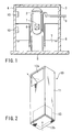
- FIG. 1 is a cross sectional view schematically showing a nuclear reactor-housing vessel in which is housed a hydrogen removing apparatus of Example 1
- FIG. 2 is an oblique view showing the hydrogen removing apparatus housed in the nuclear reactor-housing vessel shown in FIG. 1.
- a nuclear reactor pressure vessel 2 housing a nuclear reactor core 1 is housed in a nuclear reactor-housing vessel 3.
- the nuclear reactor-housing vessel 3 is filled with a nitrogen gas by exchanging an air for the nitrogen gas.
- the nuclear reactor-housing vessel 3 comprises an upper dry well 4 surrounding the nuclear reactor pressure vessel 2, a lower dry well 5, and a wet well 8 communicating with the upper dry well 4 via a vent pipe 6 and having a suppression pool 7 arranged therein.
- a nuclear reactor primary cooling pipe such as a main steam pipe 9 is connected to the nuclear reactor pressure vessel 2.
- Two hydrogen removing apparatus 10 are mounted in portions of the inner wall of the nuclear reactor-housing vessel 3 in which the upper dry well 4 and the wet well 8 are positioned, respectively.
- Each of the hydrogen removing apparatus is provided with a reactor 11 mounted to the inner wall of the nuclear reactor-housing vessel 3, as shown in FIG. 2.
- the reactor 11 is provided with openings 12a, 12b.
- the opening 12a is formed in an upper portion of the side wall on the opposite side of the back surface abutting against the inner wall of the nuclear reactor-housing vessel.
- the opening 12b is formed in a bottom portion of the reactor 11.
- a catalyst bed 13 housing a catalyst for synthesizing ammonia from nitrogen and hydrogen is housed in the reactor 11.
- the catalyst bed 13 consists of the catalyst and a carrier of the catalyst.
- the catalyst bed 13 is formed by, for example, coating the inner wall of the reactor 11 with the catalyst to form a catalyst layer. It is not absolutely necessary for the catalyst bed 13 to be in the form of a layer, provided that the catalyst bed 13 is fixed within the reactor 11.
- the hydrogen removing apparatus arranged within the nuclear reactor-housing vessel is operated as follows.
- the ammonia synthesizing reaction is an exothermic reaction. Therefore, the gas within the reactor 11 is heated so as to be moved upward within the reactor 11 and discharged through the opening 12a formed in an upper portion of the side wall. As a result, the atmosphere gas within the nuclear reactor-housing vessel 3 is introduced into the reactor 11 through the opening 12b at the bottom portion of the reactor 11. It follows that it is possible to introduce the atmosphere gas within the nuclear reactor-housing vessel 3 into the catalyst bed 13 within the reactor 11 by the natural circulating stream of the gas. In other words, the heat of the catalytic reaction performs the function of the driving source of the natural circulating stream of the gas. As a result, it is unnecessary to use a dynamic equipment such as a fan, making it possible to realize a small hydrogen removing apparatus that is advantageous in the manufacturing cost and the maintenance.
- the hydrogen gas generated within the nuclear reactor-housing vessel is allowed to react with the nitrogen gas in Example 1 to synthesize ammonia so as to decrease the gas volume within the nuclear reactor-housing vessel to half the total volume of the hydrogen gas and the nitrogen gas. It follows that the pressure elevation caused by the hydrogen gas generation can be suppressed, or the pressure within the nuclear reactor-housing vessel can be lowered. It is also possible to make it unnecessary to install a dynamic equipment such as a fan so as to realize a small hydrogen removing apparatus that is advantageous in the manufacturing cost and the maintenance.
- the volume of the gas within the vessel can be decreased to half the total volume of the hydrogen gas and the nitrogen gas within the vessel by the ammonia synthesizing reaction carried out in the presence of the catalyst bed within the reactor between the hydrogen gas and the nitrogen gas.
- the synthesized ammonia is highly soluble in water and, thus, can be dissolved in water within the suppression pool arranged within the nuclear reactor-housing vessel so as to effectively remove ammonia. As a result, the pressure elevation caused by the hydrogen gas generation within the nuclear reactor-housing vessel can be suppressed more effectively.
- the synthesized ammonia is discharged into the nuclear reactor-housing vessel 3 through the opening 12a formed in an upper portion of the side wall of the reactor 11. Also, the nitrogen, oxygen and hydrogen gases containing ammonia discharged from the hydrogen removing apparatus 10 arranged within the upper dry well 4 are moved through the vent pipe 6 into the wet well 8 so as to be combined with the nitrogen, oxygen and hydrogen gases containing ammonia discharged from the hydrogen removing apparatus 10 arranged within the wet well 8. It should be noted that nitrogen, oxygen and hydrogen gases are scarcely dissolved in water. On the other hand, ammonia is highly soluble in water and, thus, is dissolved in the water within the suppression pool 7 arranged within the wet well 8 so as to remove ammonia from the atmosphere within the nuclear reactor-housing vessel.
- Example 1 the hydrogen removing apparatus 10 is arranged within each of the upper dry well 4 and the wet well 8. However, it is possible to arrange the hydrogen removing apparatus 10 within one of these wells 4 and 8. In the case of using only one hydrogen removing apparatus, it is desirable to arrange the hydrogen removing apparatus 10 within the wet well 8. It should be noted in this connection that, if the nuclear reactor primary pipe is ruptured, the nitrogen, oxygen and hydrogen gases within the dry wells 4 and 5 are caused to be moved into the wet well 8 through the vent pipe 6 by the steam discharged in a large amount into the upper and lower dry wells 4 and 5. Naturally, the partial pressures of the hydrogen and nitrogen gases are increased within the wet well 8.
- the hydrogen removing rate achieved by the catalytic ammonia synthesizing reaction can be increased if the hydrogen removing apparatus 10 is arranged within the wet well 8, compared with the case where the hydrogen removing apparatus 10 is arranged within the upper dry well 4 or 5.
- the hydrogen gas can be removed efficiently by arranging the hydrogen removing apparatus 10 in the free space within the wet well 8.
- Example 2 is directed to a suitable shape of the catalyst bed used in the hydrogen removing apparatus of Example 1 described above.
- FIG. 7A is an oblique view showing a cartridge type catalyst bed 13 used in the hydrogen removing apparatus of Example 2, which is arranged within a nuclear reactor-housing vessel
- FIG. 7B is an oblique view showing the cartridge 14 constituting the catalyst bed shown in FIG. 7A.
- Catalysts 15 molded in a granular shape are loaded in the plate-like cartridge 15.
- the catalyst bed 13, which is arranged within the reactor 11 shown in FIG. 2, is formed by arranging a plurality cartridges 14 a desired distance apart from each other. It should be noted that the clearance between adjacent cartridges 14 provides a gas passageway substantially perpendicular to the bottom surface of the reactor 11.
- the surface layer of the cartridge 14 is formed of a porous material or a mesh-like material such that the gaseous materials within the reactor are circulated into the inner space of the cartridge 14 through the porous or mesh-like surface layer.
- the catalyst bed 13 is formed of a plurality of cartridges 14 and a gas flow passageway extending substantially perpendicular to the bottom surface of the reactor is formed in the clearance between adjacent cartridges 14. Therefore, the gaseous materials within the nuclear reactor-housing vessel are introduced into the reactor arranged in the hydrogen removing apparatus as shown in FIG. 1 so as to be brought into contact with the granular catalyst particles arranged within the cartridges 14.
- the ammonia synthesizing reaction which is exothermic, is carried out between the nitrogen gas and the hydrogen gas so as to promote formation of a natural circulating gas stream within the reactor.
- a natural circulating gas stream is formed between the two openings of the reactor and the inner space of the nuclear reactor-housing vessel without using a dynamic equipment.
- an aerosol type catalyst poison material is contained in the gaseous materials within the nuclear reactor-housing vessel together with the hydrogen, nitrogen and oxygen gases. If the catalyst poison material is attached to the catalyst, the catalytic activity of the catalyst is impaired. In the catalyst bed of the construction shown in FIG. 7A, however, a gas passageway is formed in the clearance between adjacent cartridges 14 within the reactor (not shown). As a result, the aerosol within the gaseous materials moved upward through the gas passageway is moved upward as it is and scarcely enters the cartridge 14 because the catalyst poison material in the form of an aerosol has a specific gravity larger than that of any of the other gaseous materials such as the hydrogen gas.
- any of the other gaseous materials such as the hydrogen gas has a small specific gravity and, thus, is rapidly diffused into the cartridge 14 in place of being moved upward through the gas passageway formed between adjacent cartridges 14. It follows that it is possible to prevent the catalyst poison material in the form of an aerosol from being attached to the surface of the catalyst particle loaded in the cartridge 14 by utilizing the difference in the diffusion rate into the cartridge 14 between the reactant gaseous materials and the catalyst poison material, the difference in the diffusion rate being derived from the difference in the specific gravity between the two.
- the catalyst bed 13 in Example 2 consists of a plurality of catalyst cartridges 14, the periodic inspection of the catalytic performance and renewal of the cartridge 14 can be carried out without difficulty.
- Example 3 is directed to another preferred shape of the catalyst bed used in the hydrogen removing apparatus of Example 1.
- FIG. 8 is an oblique view showing a catalyst bed 13 of Example 3, which is used in a hydrogen removing apparatus arranged in a nuclear reactor-housing vessel.
- the catalyst bed 13 is formed by loading catalyst particles 15 molded in a granular shape in a cylindrical cartridge 16.
- Gas circulating sections 17a, 17b which are in the form of, for example, a mesh, are formed in the top portion and the bottom portion, respectively, of the cylindrical cartridge 16. It is possible to use a porous material for forming the gas circulating sections 17a, 17b.
- the catalyst bed 13 of the particular construction is housed in the reactor 11 shown in FIG. 2, and the gaseous materials within the reactor are circulated into the cartridge 16 through the gas circulating sections 17a, 17b.
- the catalyst bed 13 is formed of the cylindrical cartridge 16 having the gas circulating sections 17a, 17b formed in the top and bottom portions thereof, respectively. Therefore, the gaseous materials within the nuclear reactor-housing vessel shown in FIG. 1 are introduced through the openings of the reactor arranged in the hydrogen removing apparatus into the reactor so as to be brought into contact with the granular catalyst particles. As a result, an ammonia synthesizing reaction, which is exothermic, is brought about so as to promote formation of a natural circulating gas stream within the reactor. It follows that a natural gas circulating stream is formed between the two openings of the reactor and the inner space of the nuclear reactor-housing vessel without using a dynamic equipment, as in Example 2.
- the catalyst 15 loaded in the catalyst bed 13 is molded in a granular shape, the catalyst particles 15 can be loaded in the cylindrical cartridge 16 in a high density, making it possible to further improve the hydrogen removing efficiency achieved by the catalytic ammonia synthesizing reaction.
- Example 4 is directed to another suitable shape of the catalyst bed used in the hydrogen removing apparatus of Example 1.
- FIG. 9 is an oblique view showing a catalyst bed 13 of Example 4, which is used in a hydrogen removing apparatus arranged in a nuclear reactor-housing vessel.
- the catalyst bed 13 in Example 4 consists of a catalyst carrier molded to have a honeycomb structure and a catalytic metal as well as a co-catalyst component, as desired, which are supported on a large number of meshes 18 of the catalyst carrier having a honeycomb structure. It is desirable for the honeycomb structure to have meshes falling within a range of between 100 and 1200 cells/inch 2 .
- the catalyst bed 13 is housed in the reactor 11 shown in FIG. 2. In the catalyst bed 13, the gaseous materials within the reactor flow through the meshes 18 inside the honeycomb structure.
- the catalyst bed 13 has a honeycomb structure and the gaseous materials flow through the meshes 18 of the honeycomb structure. Therefore, the gaseous materials within the nuclear reactor-housing vessel are introduced through the openings of the reactor of the hydrogen removing apparatus so as to be brought into contact with the catalyst supported by the meshes 18 of the honeycomb structure. As a result, an ammonia synthesizing reaction, which is exothermic, is brought about so as to promote formation of a natural circulating gas stream within the reactor. It follows that a natural gas circulating stream is formed between the two openings of the reactor and the inner space of the nuclear reactor-housing vessel without using a dynamic equipment, as in Example 2.
- the meshes of the honeycomb structure are set to fall within a range of between 100 and 1200 cells/inch 2 , i.e., between 19.7 and 236.2 cells/cm 2 .
- the hydrogen removing rate achieved in the presence of the catalyst is increased and the natural gas circulating rate can be increased.
- Example 5 is directed to the catalyst bed used in the hydrogen removing apparatus of Example 1 and to a suitable shape of the cartridge forming the catalyst bed.
- FIGS. 10A, 10B, and 10C are cross sectional views each schematically showing a part of the catalyst bed of Example 5.
- the catalyst bed 13 shown in FIG. 10A comprises a cylindrical cartridge 16 having gas circulating sections (not shown), which are in the form of, for example, meshes, formed in the top and bottom portions, respectively, and a cylindrical body 19 having a small diameter and arranged concentric relative to the cartridge 16.
- Granular catalyst particles 15 are loaded in the clearance between the cylindrical cartridge 16 and the cylindrical body 19 having a small diameter. Further, granular heat generating particles 20 are loaded within the cylindrical body 19 having a small diameter.
- the catalyst bed 13 shown in FIG. 10B comprises a cylindrical cartridge 16 having gas circulating sections (not shown), which are in the form of, for example, meshes, formed in the top and bottom portions, respectively, and a cylindrical body 19 having a small diameter and arranged concentric relative to the cartridge 16.
- the granular heat generating particles 20 are loaded in the clearance between the cylindrical cartridge 16 and the cylindrical body 19 having a small diameter. Further, the granular catalyst particles 15 are loaded within the cylindrical body 19 having a small diameter.
- the catalyst bed 13 shown in FIG. 10C comprises a cylindrical cartridge 16 having gas circulating sections (not shown), which are in the form of, for example, meshes, formed in the top and bottom portions, respectively.
- gas circulating sections not shown
- the granular catalyst particles 15 and the granular heat generating particles 20 are loaded in mutual contact within the cylindrical cartridge 16.
- Example 5 e.g., the catalyst bed 13 shown in FIG. 10A, a reaction takes place between the granular heat generating particles 20, e.g., calcium oxide particles, loaded within the cylindrical body having a small diameter, which is arranged within the cylindrical cartridge 16, and steam to form calcium hydroxide, when steam is generated within the nuclear reactor-housing vessel by the breakage of the nuclear reactor primary pipe and enters the catalyst bed through the openings of the reactor of the hydrogen removing apparatus, as shown below: CaO + H 2 O ⁇ Ca(OH) 2 + 15.2 kcal
- the granular catalyst particles 15 loaded in the clearance between the cylindrical cartridge 16 and the cylindrical body 19 having a small diameter are heated and, thus, the granular catalyst particles 15 are activated. Also, even if water droplets causing the catalytic activities to be lowered are present on the surface of the granular catalyst particles 15, the water droplets are removed from the surface of the granular catalyst particles 15 by the heat generated from the granular heat generating particles 20 before the granular catalyst particles 15 are heated to the operating temperature. It follows that satisfactory catalytic activities are maintained.
- the catalyst bed shown in each of FIGS. 10B and 10C also produces the function and effect described above.
- the gaseous materials within the nuclear reactor-housing vessel are forcedly introduced into the reactor so as to promote the gas substitution in the catalyst bed.
- ammonia formed by the catalytic reaction is forcedly removed by the fan from the reaction site so as to further improve the ammonia synthesizing reaction rate.
- the present invention provides a hydrogen removing apparatus capable of removing without fail the hydrogen gas generated within a hermetically closed space having a low oxygen concentration and filled with a nitrogen gas so as to suppress the pressure elevation caused by the hydrogen generation within the closed space and, thus, to ensure satisfactory conditions within the closed space.
- the present invention also provides a hydrogen removing apparatus that can be arranged within a nuclear reactor-housing vessel and that permits effectively suppressing the pressure elevation caused by the hydrogen gas generation within the nuclear reactor-housing vessel without releasing the gaseous materials within the nuclear reactor-housing vessel to the outer atmosphere.
Landscapes
- Chemical & Material Sciences (AREA)
- Engineering & Computer Science (AREA)
- Physics & Mathematics (AREA)
- Organic Chemistry (AREA)
- Chemical Kinetics & Catalysis (AREA)
- Analytical Chemistry (AREA)
- Plasma & Fusion (AREA)
- Environmental & Geological Engineering (AREA)
- High Energy & Nuclear Physics (AREA)
- Materials Engineering (AREA)
- Fluid Mechanics (AREA)
- General Engineering & Computer Science (AREA)
- Biomedical Technology (AREA)
- Oil, Petroleum & Natural Gas (AREA)
- General Chemical & Material Sciences (AREA)
- Health & Medical Sciences (AREA)
- Inorganic Chemistry (AREA)
- Business, Economics & Management (AREA)
- Emergency Management (AREA)
- Catalysts (AREA)
Abstract
Description
Claims (12)
- A hydrogen removing apparatus (10), characterized by comprising:a reactor (11) having two openings (12a and 12b) for introducing the outer atmosphere into the reactor (11); anda catalyst bed (13) arranged within said reactor (11) and loaded with a catalyst for an ammonia synthesizing reaction between a nitrogen gas and a hydrogen gas.
- The hydrogen removing apparatus according to claim 1, characterized in that a catalyst for a water synthesizing reaction between an oxygen gas and a hydrogen gas is further loaded in said catalyst bed arranged within said reactor.
- The hydrogen removing apparatus according to claim 1, characterized in that at least one element selected from the group consisting of Ru, Pd, Pt, Ir, W, Ag, Au, Rh and Re is used as said catalyst and said catalyst is contained in the catalyst bed in an amount of 0.1 to 50% by weight.
- The hydrogen removing apparatus according to claim 1, characterized in that said catalyst bed comprises said catalyst and a catalyst carrier consisting of at least one material selected from the group consisting of SiO2, Al2O3, TiO2, ZrO2 and C.
- The hydrogen removing apparatus according to claim 4, characterized in that said catalyst carrier has a specific surface area falling within a range of between 10 m2/g and 200 m2/g.
- The hydrogen removing apparatus according to claim 1, characterized in that said catalyst bed further contains at least one co-catalyst selected from the group consisting of CeO2, La2O3, MgO, K2O, Na2O, CaO, CsOH and CsNO3.
- The hydrogen removing apparatus according to claim 6, characterized in that said co-catalyst is contained in the catalyst bed in an amount of 1 to 30% by weight.
- The hydrogen removing apparatus according to claim 1, characterized in that said catalyst bed consists of a plurality of plate-like cartridges (14) loaded with granular catalyst particles (15) and arranged a predetermined distance apart from each other.
- The hydrogen removing apparatus according to claim 1, characterized in that said catalyst bed consists of a cylindrical cartridge (16) loaded with granular catalyst particles (15), said cartridge (16) having gas circulating sections (17a and 17b) formed in at least the top portion and the bottom portion of the cartridge (16) for circulation of the gaseous materials present both inside and outside the cartridge (16).
- The hydrogen removing apparatus according to claim 1, characterized in that said catalyst bed is in the form of a molded honeycomb structure having meshes (18) supporting at least a catalyst.
- The hydrogen removing apparatus according to claim 1, characterized in that at least one heat generating body for heating the catalyst, which is selected from the group consisting of calcium oxide, sodium oxide, strontium oxide and a hydrogen absorbing metal, is housed in said reactor.
- The hydrogen removing apparatus according to claim 1, which is arranged within a nuclear reactor-housing vessel (3) housing a nuclear reactor pressure vessel (2) in which is arranged a reactor core (1), wherein the gaseous materials within said nuclear reactor-housing vessel (3) is circulated into said reactor (11) through the openings (12a and 12b) of the reactor.
Applications Claiming Priority (2)
| Application Number | Priority Date | Filing Date | Title |
|---|---|---|---|
| JP16198499 | 1999-06-09 | ||
| JP16198499 | 1999-06-09 |
Publications (3)
| Publication Number | Publication Date |
|---|---|
| EP1059116A2 true EP1059116A2 (en) | 2000-12-13 |
| EP1059116A3 EP1059116A3 (en) | 2002-06-05 |
| EP1059116B1 EP1059116B1 (en) | 2006-04-26 |
Family
ID=15745832
Family Applications (1)
| Application Number | Title | Priority Date | Filing Date |
|---|---|---|---|
| EP00111881A Expired - Lifetime EP1059116B1 (en) | 1999-06-09 | 2000-06-09 | Hydrogen removing apparatus |
Country Status (3)
| Country | Link |
|---|---|
| US (1) | US6902709B1 (en) |
| EP (1) | EP1059116B1 (en) |
| DE (1) | DE60027503T2 (en) |
Cited By (5)
| Publication number | Priority date | Publication date | Assignee | Title |
|---|---|---|---|---|
| CN100486694C (en) * | 2005-08-31 | 2009-05-13 | 中国科学院大连化学物理研究所 | Preparation process and application of axial non-uniformness integral catalyst |
| WO2016091146A1 (en) * | 2014-12-08 | 2016-06-16 | 中广核工程有限公司 | Method, apparatus and system for measuring hydrogen concentration in containment vessel of nuclear power station |
| CN110061279A (en) * | 2018-03-01 | 2019-07-26 | 荷派克电源有限两合公司 | Reformer |
| CN113130100A (en) * | 2021-04-09 | 2021-07-16 | 哈尔滨工程大学 | Axial optimization device for hydrogen recombiner assembly unit |
| US11566830B2 (en) | 2004-06-23 | 2023-01-31 | Icegen Patent Corp. | Heat exchanger for use in cooling liquids |
Families Citing this family (7)
| Publication number | Priority date | Publication date | Assignee | Title |
|---|---|---|---|---|
| KR20080060871A (en) * | 2006-12-27 | 2008-07-02 | 유니슨 주식회사 | Equipped with metal monolith heat exchanger for hydrocarbon steam reforming |
| JP5304647B2 (en) * | 2007-06-28 | 2013-10-02 | 富士通セミコンダクター株式会社 | Heat treatment apparatus and semiconductor device manufacturing method |
| KR200464123Y1 (en) * | 2011-05-04 | 2012-12-12 | 한국원자력기술 주식회사 | Passive Auto-catalytic Recombiner |
| CN102208216B (en) * | 2011-05-18 | 2013-06-05 | 华北电力大学 | Hydrogen-explosion-preventing serious nuclear accident relieving device and method |
| CN102280147B (en) * | 2011-08-05 | 2013-12-25 | 中国船舶重工集团公司第七一八研究所 | Device for eliminating flammable gas in closed environment |
| CN110917793A (en) * | 2019-12-16 | 2020-03-27 | 湖南众鑫新材料科技股份有限公司 | Method for preparing ammonia water from low-valence vanadium waste gas |
| CN111540484A (en) * | 2020-04-21 | 2020-08-14 | 上海申核能源工程技术有限公司 | Hydrogen absorption material used under nuclear facility accident environmental condition |
Family Cites Families (9)
| Publication number | Priority date | Publication date | Assignee | Title |
|---|---|---|---|---|
| BE561984A (en) | 1956-11-01 | |||
| US4012490A (en) * | 1972-07-25 | 1977-03-15 | Airco, Inc. | Removing radioactive noble gases from nuclear process off-gases |
| US4228132A (en) * | 1973-08-10 | 1980-10-14 | Westinghouse Electric Corp. | Hydrogen-oxygen recombiner |
| GB1565074A (en) * | 1976-11-03 | 1980-04-16 | British Petroleum Co | Process for the production of ammonia |
| US4142993A (en) | 1977-12-07 | 1979-03-06 | The Research Council Of Alberta | Transition metal catalyst |
| DE4015228A1 (en) * | 1990-05-11 | 1991-11-14 | Siemens Ag | DEVICE FOR THE RECOMBINATION OF HYDROGEN AND OXYGEN AND USE OF THE DEVICE |
| ES2079933T3 (en) * | 1993-08-24 | 1996-01-16 | Anlagen Und Reaktorsicherheit | ARRANGEMENT FOR THE PASSIVE INERTIZATION OF THE GAS MIXTURE IN THE SAFETY VESSEL OF A NUCLEAR POWER PLANT. |
| JPH08297194A (en) | 1995-04-26 | 1996-11-12 | Hitachi Ltd | Hydrogen removal system |
| DE19704608C1 (en) | 1997-02-07 | 1998-06-10 | Siemens Ag | Convection-driven hydrogen recombination chimney within nuclear power plant containment |
-
2000
- 2000-06-08 US US09/589,168 patent/US6902709B1/en not_active Expired - Fee Related
- 2000-06-09 EP EP00111881A patent/EP1059116B1/en not_active Expired - Lifetime
- 2000-06-09 DE DE60027503T patent/DE60027503T2/en not_active Expired - Lifetime
Cited By (6)
| Publication number | Priority date | Publication date | Assignee | Title |
|---|---|---|---|---|
| US11566830B2 (en) | 2004-06-23 | 2023-01-31 | Icegen Patent Corp. | Heat exchanger for use in cooling liquids |
| CN100486694C (en) * | 2005-08-31 | 2009-05-13 | 中国科学院大连化学物理研究所 | Preparation process and application of axial non-uniformness integral catalyst |
| WO2016091146A1 (en) * | 2014-12-08 | 2016-06-16 | 中广核工程有限公司 | Method, apparatus and system for measuring hydrogen concentration in containment vessel of nuclear power station |
| CN110061279A (en) * | 2018-03-01 | 2019-07-26 | 荷派克电源有限两合公司 | Reformer |
| CN110061279B (en) * | 2018-03-01 | 2023-04-11 | 荷派克电源有限两合公司 | Recombination device |
| CN113130100A (en) * | 2021-04-09 | 2021-07-16 | 哈尔滨工程大学 | Axial optimization device for hydrogen recombiner assembly unit |
Also Published As
| Publication number | Publication date |
|---|---|
| US6902709B1 (en) | 2005-06-07 |
| EP1059116A3 (en) | 2002-06-05 |
| DE60027503D1 (en) | 2006-06-01 |
| EP1059116B1 (en) | 2006-04-26 |
| DE60027503T2 (en) | 2006-12-14 |
Similar Documents
| Publication | Publication Date | Title |
|---|---|---|
| EP1059116B1 (en) | Hydrogen removing apparatus | |
| EP0980705B1 (en) | Apparatus for removing flammable gas | |
| EP1138383B1 (en) | Method for oxidising carbon monoxide contained in hydrogen | |
| JP2018119821A (en) | Nuclear power plant | |
| CA2129774C (en) | Device for passively inerting the gas mixture in the reactor containment of a nuclear power plant | |
| CN2901504Y (en) | Hydrogen and oxygen compounding device without external power supply | |
| JP4212222B2 (en) | Hydrogen removal device | |
| CA2521404C (en) | Integrated fuel processor apparatus and enclosure and methods of using same | |
| JP6366532B2 (en) | Filter vent method, filter vent device, and nuclear power plant | |
| US5499279A (en) | Apparatus for removing free hydrogen from a gas mixture containing hydrogen and oxygen | |
| US20250281781A1 (en) | Quenching device, hydrogen production device, hydrogen production method and reactor for photochemical reaction | |
| US6923948B2 (en) | Combined heat and power plant and a process for the operation thereof | |
| WO2020121714A1 (en) | Organic iodine collection device and organic iodine collection method | |
| JP4073065B2 (en) | Reactor containment hydrogen removal equipment | |
| JP3566303B2 (en) | Method and apparatus for initiating the reaction between hydrogen and oxygen in containment of a nuclear reactor | |
| JP2014020997A (en) | Hydrogen remover and hydrogen removing method for reactor containment vessel | |
| EP0160648A1 (en) | Means and procedure for removal of carbon dioxide | |
| JP4443861B2 (en) | Method and apparatus for removing hydrogen from containment vessel | |
| JP5632272B2 (en) | Hydrogen treatment facility for reactor containment vessel | |
| JP2001228296A (en) | Canister and lid for it | |
| RU77488U1 (en) | PASSIVE AUTOCATALYTIC RECOMBINATOR OF HYDROGEN AND OXYGEN FOR OPERATION IN A MEDIUM WITH A HIGH HYDROGEN CONTENT | |
| JP7304470B2 (en) | Organic iodine collection device and organic iodine collection method | |
| JPH09318782A (en) | Primary containment vessel | |
| JP2003513252A (en) | Apparatus for removing hydrogen from a gas mixture flowing through a conduit | |
| JPH10221477A (en) | Reactor containment vessel |
Legal Events
| Date | Code | Title | Description |
|---|---|---|---|
| PUAI | Public reference made under article 153(3) epc to a published international application that has entered the european phase |
Free format text: ORIGINAL CODE: 0009012 |
|
| 17P | Request for examination filed |
Effective date: 20000609 |
|
| AK | Designated contracting states |
Kind code of ref document: A2 Designated state(s): AT BE CH CY DE DK ES FI FR GB GR IE IT LI LU MC NL PT SE |
|
| AX | Request for extension of the european patent |
Free format text: AL;LT;LV;MK;RO;SI |
|
| PUAL | Search report despatched |
Free format text: ORIGINAL CODE: 0009013 |
|
| AK | Designated contracting states |
Kind code of ref document: A3 Designated state(s): AT BE CH CY DE DK ES FI FR GB GR IE IT LI LU MC NL PT SE |
|
| AX | Request for extension of the european patent |
Free format text: AL;LT;LV;MK;RO;SI |
|
| RIC1 | Information provided on ipc code assigned before grant |
Free format text: 7B 01J 12/00 A, 7B 01J 19/00 B, 7B 01D 53/86 B, 7C 01C 1/04 B, 7G 21D 3/08 B, 7G 21C 9/06 B, 7G 21C 19/317 B |
|
| AKX | Designation fees paid |
Designated state(s): DE FR |
|
| 17Q | First examination report despatched |
Effective date: 20030904 |
|
| GRAP | Despatch of communication of intention to grant a patent |
Free format text: ORIGINAL CODE: EPIDOSNIGR1 |
|
| GRAS | Grant fee paid |
Free format text: ORIGINAL CODE: EPIDOSNIGR3 |
|
| GRAA | (expected) grant |
Free format text: ORIGINAL CODE: 0009210 |
|
| AK | Designated contracting states |
Kind code of ref document: B1 Designated state(s): DE FR |
|
| REF | Corresponds to: |
Ref document number: 60027503 Country of ref document: DE Date of ref document: 20060601 Kind code of ref document: P |
|
| ET | Fr: translation filed | ||
| PLBE | No opposition filed within time limit |
Free format text: ORIGINAL CODE: 0009261 |
|
| STAA | Information on the status of an ep patent application or granted ep patent |
Free format text: STATUS: NO OPPOSITION FILED WITHIN TIME LIMIT |
|
| 26N | No opposition filed |
Effective date: 20070129 |
|
| PGFP | Annual fee paid to national office [announced via postgrant information from national office to epo] |
Ref country code: DE Payment date: 20120607 Year of fee payment: 13 |
|
| PGFP | Annual fee paid to national office [announced via postgrant information from national office to epo] |
Ref country code: FR Payment date: 20120619 Year of fee payment: 13 |
|
| REG | Reference to a national code |
Ref country code: FR Ref legal event code: ST Effective date: 20140228 |
|
| REG | Reference to a national code |
Ref country code: DE Ref legal event code: R119 Ref document number: 60027503 Country of ref document: DE Effective date: 20140101 |
|
| PG25 | Lapsed in a contracting state [announced via postgrant information from national office to epo] |
Ref country code: DE Free format text: LAPSE BECAUSE OF NON-PAYMENT OF DUE FEES Effective date: 20140101 |
|
| PG25 | Lapsed in a contracting state [announced via postgrant information from national office to epo] |
Ref country code: FR Free format text: LAPSE BECAUSE OF NON-PAYMENT OF DUE FEES Effective date: 20130701 |