EP1059050A2 - Mobile storage system - Google Patents
Mobile storage system Download PDFInfo
- Publication number
- EP1059050A2 EP1059050A2 EP00304733A EP00304733A EP1059050A2 EP 1059050 A2 EP1059050 A2 EP 1059050A2 EP 00304733 A EP00304733 A EP 00304733A EP 00304733 A EP00304733 A EP 00304733A EP 1059050 A2 EP1059050 A2 EP 1059050A2
- Authority
- EP
- European Patent Office
- Prior art keywords
- base
- storage
- shim
- engagement
- mounting
- Prior art date
- Legal status (The legal status is an assumption and is not a legal conclusion. Google has not performed a legal analysis and makes no representation as to the accuracy of the status listed.)
- Withdrawn
Links
- 238000003860 storage Methods 0.000 title claims abstract description 293
- 230000007246 mechanism Effects 0.000 claims abstract description 36
- 238000007667 floating Methods 0.000 abstract description 4
- 230000009977 dual effect Effects 0.000 abstract description 2
- 230000000712 assembly Effects 0.000 description 10
- 238000000429 assembly Methods 0.000 description 10
- 238000010276 construction Methods 0.000 description 5
- 238000009434 installation Methods 0.000 description 3
- 238000003466 welding Methods 0.000 description 3
- 230000006835 compression Effects 0.000 description 2
- 238000007906 compression Methods 0.000 description 2
- 230000001419 dependent effect Effects 0.000 description 2
- 238000005516 engineering process Methods 0.000 description 2
- 230000000717 retained effect Effects 0.000 description 2
- 238000013459 approach Methods 0.000 description 1
- 238000005452 bending Methods 0.000 description 1
- 238000004519 manufacturing process Methods 0.000 description 1
- 238000000034 method Methods 0.000 description 1
- 230000003014 reinforcing effect Effects 0.000 description 1
- 206010040560 shock Diseases 0.000 description 1
Images



Classifications
-
- A—HUMAN NECESSITIES
- A47—FURNITURE; DOMESTIC ARTICLES OR APPLIANCES; COFFEE MILLS; SPICE MILLS; SUCTION CLEANERS IN GENERAL
- A47B—TABLES; DESKS; OFFICE FURNITURE; CABINETS; DRAWERS; GENERAL DETAILS OF FURNITURE
- A47B53/00—Cabinets or racks having several sections one behind the other
- A47B53/02—Cabinet systems, e.g. consisting of cabinets arranged in a row with means to open or close passages between adjacent cabinets
-
- A—HUMAN NECESSITIES
- A47—FURNITURE; DOMESTIC ARTICLES OR APPLIANCES; COFFEE MILLS; SPICE MILLS; SUCTION CLEANERS IN GENERAL
- A47B—TABLES; DESKS; OFFICE FURNITURE; CABINETS; DRAWERS; GENERAL DETAILS OF FURNITURE
- A47B88/00—Drawers for tables, cabinets or like furniture; Guides for drawers
- A47B88/40—Sliding drawers; Slides or guides therefor
- A47B88/42—Vertically-oriented drawers, i.e. drawers where the height exceeds the width
-
- A—HUMAN NECESSITIES
- A47—FURNITURE; DOMESTIC ARTICLES OR APPLIANCES; COFFEE MILLS; SPICE MILLS; SUCTION CLEANERS IN GENERAL
- A47B—TABLES; DESKS; OFFICE FURNITURE; CABINETS; DRAWERS; GENERAL DETAILS OF FURNITURE
- A47B88/00—Drawers for tables, cabinets or like furniture; Guides for drawers
- A47B88/40—Sliding drawers; Slides or guides therefor
- A47B88/453—Actuated drawers
- A47B88/46—Actuated drawers operated by mechanically-stored energy, e.g. by springs
- A47B88/467—Actuated drawers operated by mechanically-stored energy, e.g. by springs self-closing
-
- B—PERFORMING OPERATIONS; TRANSPORTING
- B65—CONVEYING; PACKING; STORING; HANDLING THIN OR FILAMENTARY MATERIAL
- B65G—TRANSPORT OR STORAGE DEVICES, e.g. CONVEYORS FOR LOADING OR TIPPING, SHOP CONVEYOR SYSTEMS OR PNEUMATIC TUBE CONVEYORS
- B65G1/00—Storing articles, individually or in orderly arrangement, in warehouses or magazines
- B65G1/02—Storage devices
- B65G1/04—Storage devices mechanical
- B65G1/10—Storage devices mechanical with relatively movable racks to facilitate insertion or removal of articles
-
- F—MECHANICAL ENGINEERING; LIGHTING; HEATING; WEAPONS; BLASTING
- F16—ENGINEERING ELEMENTS AND UNITS; GENERAL MEASURES FOR PRODUCING AND MAINTAINING EFFECTIVE FUNCTIONING OF MACHINES OR INSTALLATIONS; THERMAL INSULATION IN GENERAL
- F16B—DEVICES FOR FASTENING OR SECURING CONSTRUCTIONAL ELEMENTS OR MACHINE PARTS TOGETHER, e.g. NAILS, BOLTS, CIRCLIPS, CLAMPS, CLIPS OR WEDGES; JOINTS OR JOINTING
- F16B2200/00—Constructional details of connections not covered for in other groups of this subclass
- F16B2200/40—Clamping arrangements where clamping parts are received in recesses of elements to be connected
Definitions
- This invention relates to storage systems, and more particularly to a high density storage arrangement in which a series of storage cabinets are mounted side-by-side, without aisles between adjacent cabinets, and in which the storage cabinets can be moved between an extended, access position and a retracted, storage position.
- Conventional storage or shelving systems employ a number of storage cabinets which are placed onto a supporting surface such as a floor, with an aisle between adjacent cabinets so as to provide access to the front of each cabinet.
- This type of an arrangement is suitable for low density applications, since significant floor space is required for the aisles between adjacent cabinets.
- High density storage systems place adjacent cabinets close together and eliminate the aisles between cabinets.
- the cabinets are movable on lateral tracks mounted in the supporting surface, so as to separate adjacent cabinets to form an aisle so as to provide access to the front of a desired one of the cabinets.
- Systems of this type typically utilize a number of carriages which are movably mounted to the tracks, and a number of storage cabinets are mounted to each carriage. This type of system greatly increases the efficiency of a given amount of storage space by eliminating the aisles between adjacent storage cabinets.
- high density storage system is very suitable in situations where the storage space can accommodate a number of rows of storage cabinets, with each row being made up of a number of storage cabinets.
- high density storage is required in spaces which cannot accommodate several cabinets in a row, or in spaces in which a large number of single cabinets are placed in a side-by-side relationship.
- mount a storage cabinet to a structure which allows the cabinet to be moved between a retracted, storage position and an extended, access position.
- the storage cabinets are placed in a closely packed, side-by-side arrangement such that there is very little space between adjacent cabinets.
- the cabinet To gain access to items stored on one of the cabinets, the cabinet is moved to its extended, access position in which the cabinet is moved outwardly relative to the adjacent cabinets, to provide access to the front of the cabinet. Movement of the cabinet between its retracted, storage position and its extended, access position is typically accomplished by applying a manual pull-out or push-in force to the desired cabinet.
- a storage assembly adapted for movement relative to a supporting surface between first and second positions includes a storage member and a guide assembly for guiding movement of the storage member between the first and second positions.
- the storage member includes a base at its lower end, and the base has a set of rotatable wheels for engagement with the supporting surface to provide movement of the storage member thereon.
- the guide assembly includes a mounting member adapted to be secured to the supporting surface, and an extendible and retractable guide mechanism interposed between the mounting member and the storage member base for guiding movement of the storage member.
- the storage member is preferably in the form of a cabinet releasably engaged with the base.
- the base preferably includes an upper wall and a pair of dependent side walls extending downwardly from the upper wall.
- the upper wall and side walls define an interior, and the set of rotatable wheels are in the form of at least one pair of spaced wheels, with each wheel being rotatably mounted to wheel mounting structure which is secured to an underside defined by the top wall of the base and located within the interior of the base.
- the extendible and retractable guide mechanism is preferably in the form of a telescoping slide arrangement interposed between the mounting member and the base.
- a mounting rail is secured to the mounting member and is engageable with the supporting surface, and the telescoping slide arrangement is preferably mounted to the mounting rail.
- the storage member and the base extend along a horizontal longitudinal axis, and the guide assembly is constructed and arranged to provide movement of the storage member and the base along the horizontal longitudinal axis of the storage member.
- the storage member is preferably in the form of a cabinet which opens in a direction transverse to its longitudinal axis. In this manner, the cabinet can be pulled out on the supporting surface to an extended position in which the front of the cabinet is accessible, and can then be pushed back to a storage position between a pair of adjacent cabinets when access to the cabinet is no longer required.
- a storage member having a base located at its lower end is interconnected with a guide assembly for guiding movement of the storage member between first and second positions.
- the guide assembly includes an inner mounting member adapted to be secured to the supporting surface, and an axially telescoping slide assembly interposed between the inner mounting member and the storage member base.
- the telescoping slide assembly includes a fixed-position guide member mounted to and extending from the mounting member, and axially movable extension member interconnected with the guide member and the storage member base.
- the guide member and the extension member are operable to guide movement of the storage member between the first and second positions.
- the base preferably includes a set of rotatable wheels for engagement with the supporting surface to provide movement of the storage member between the first and second positions.
- the base is interconnected with the extension member by means of engagement structure interposed between the base and the extension member.
- a storage assembly for movement on a supporting surface between first and second positions includes a storage member and a guide arrangement interconnected with the supporting surface.
- the storage member includes a base having a movable supporting arrangement engaged with the supporting surface for movably supporting the base on the supporting surface.
- Engagement structure is interposed between the base and the guide arrangement, and the engagement structure is constructed and arranged to accommodate relative vertical movement between the base and the guide arrangement as the base is moved between the first and second positions.
- the guide arrangement is preferably in the form of a fixed-position guide member interconnected with the supporting surface and an axially movable extension member interconnected with the fixed-position guide member and with the storage member base.
- the engagement structure is interconnected between the base and the extension member, and is preferably in the form of an opening associated with the base and an engagement member mounted to the extension member and extending into the opening.
- the engagement member is vertically movable within the opening to accommodate relative vertical movement between the guide arrangement and the base, as the storage member and base are moved between the first and second positions.
- the opening is preferably formed in a horizontal wall associated with the base, and the engagement member may be in the form of an upstanding cylindrical member adapted for removable mounting to the extension member, and which is received within the opening.
- the article of furniture may be in the form of a storage member, which defines a lower end including a pair of spaced surfaces.
- a locking slot is associated with the base, and defines a laterally facing entrance.
- the locking slot is located between the pair of spaced surfaces of the storage member, and a locking member is releasably engageable within the locking slot.
- the locking member defines a pair of spaced engagement surfaces located one on either side of the locking slot, and each engagement surface is adapted to overlie one of the spaced surfaces of the storage member.
- the locking slot is configured such that movement of the locking member into the locking slot inwardly of the entrance is operable to move the engagement surfaces of the locking member into contact with the spaced surfaces of the storage member to maintain engagement of the storage member with the base.
- the pair of spaced surfaces of the storage member are preferably defined by a pair of spaced horizontal frame members forming a part of the structure of the storage member, and the base preferably includes an upper support surface for supporting the storage member thereabove.
- the pair of spaced horizontal frame members are located adjacent the upper support surface of the movable base.
- the base is preferably movable by means of at least of one set of laterally spaced wheels.
- Each wheel is rotatably mounted to wheel mounting structure interconnected with the upper support surface of the base, and located beneath one of the spaced horizontal frame members of the storage member. In this manner, the weight of the storage member is transferred directly through the wheel mounting structure to the wheels.
- the locking member is preferably in the form of an elongated rod defining a pair of spaced ends. Each end of the locking rod overlies one of the spaced horizontal frame members of the storage member.
- the locking slot is defined by a mounting member interconnected with the upper support surface of the base, and at least an upper portion of the laterally facing entrance of the locking slot is located vertically above the pair of spaced surfaces defined by the pair of spaced horizontal frame members of the storage member.
- the locking slot is configured such that movement of the elongated rod laterally into the locking slot moves the spaced ends of the elongated rod downwardly against the spaced surfaces defined by the pair of spaced horizontal frame members, so as to clamp the frame members, and thereby the storage member, to the base.
- the upper portion of the locking slot is preferably defined by a downwardly angled engagement surface which extends inwardly from the slot entrance, and the slot further includes a detent surface located inwardly of the downwardly angled engagement surface for engaging the elongated rod and retaining the elongated rod within the slot, in a position wherein the spaced ends of the elongated rod engage the spaced surfaces defined by the pair of spaced horizontal frame members of the storage member.
- a storage assembly movable relative to a supporting surface between first and second positions includes a storage member having a base located toward its lower end, and a guide assembly for guiding movement of the storage member between the first and second positions.
- the base includes a movable supporting arrangement engaged with the supporting surface for supporting the storage member on the supporting surface.
- the guide assembly includes a mounting member adapted to be secured to the supporting surface, and a guide member secured to and extending from the mounting member and interconnected with the base.
- a retainer mechanism is operable to releasably maintain the storage member in at least the first position.
- the retainer mechanism is in the form of a catch member mounted to one of the base and the guide assembly, and a movable retainer member mounted to the other of the base and the guide assembly.
- the catch member includes an engagement surface with which the movable retainer member is engageable, to maintain the storage member in the first position.
- the retainer member is movable out of engagement with the engagement surface upon application of an axial force to the storage member tending to move the storage member from its first position toward its second position, to enable movement of the storage member to its second position. Return movement of the storage member toward its first position results in subsequent engagement of the retainer member with the engagement surface to releasably retain the storage member in its first position.
- the base includes a set of rotatable wheels for engagement with the supporting surface to provide movement of the storage member thereon between the first and second positions.
- the catch member includes a ramped surface extending from the engagement surface, and the movable retainer member is engageable with the ramped surface for guiding the movable retainer member into engagement with the engagement surface as the storage member is moved toward its first position.
- the movable retainer member is preferably mounted to a housing for movement between an outward position and an inward position, and a biasing element is interposed between the housing and the retainer member for biasing the retainer member toward its outward position.
- Movement of the storage member toward the first position causes engagement of the retainer member with the ramped surface, to move the retainer member toward its inward position against the force of the biasing element. Movement of the retainer member past the engagement surface, as the storage member is moved to its first position, results in movement of the retainer member toward its outward position under the influence of the biasing element, to engage the retainer member with the engagement surface.
- the catch member is preferably mounted to the mounting member of the guide assembly, and the movable retainer member and housing are preferably mounted to a lower wall defined by the base which overlies at least a portion of the mounting member when the storage member is in its first position.
- a resilient bumper is preferably interposed between the mounting member and the base for cushioning impact between the mounting member and the base when the storage member is moved to its first position.
- a shim system is adapted for use in combination with an article of furniture and a support, such as a movable base, for adjusting the elevation of the article of furniture relative to the support.
- the shim system includes at least one upper shim member and at least one lower shim member mounted to the support.
- the upper shim member is mounted in a fixed position to the support and the lower shim member is movably mounted to and between the support and the upper shim member.
- a pair of spaced connectors extend between and interconnect the support with the upper shim member for fixing the upper shim member relative to the support.
- the lower shim member includes a movable mounting arrangement for providing movement of the lower shim member between an extended, shimming position and a retracted or withdrawn position.
- the lower shim member In the shimming position, the lower shim member is interposed between the article of furniture and the support for raising the elevation of the article of furniture relative to the support.
- the withdrawn position In the withdrawn position, the lower shim member is withdrawn from between the article of furniture and the support to provide direct engagement therebetween.
- the lower shim member includes slot structure through which the pair of spaced connectors extend, to enable movement of the lower shim member relative to the support and relative to the upper shim member.
- the upper shim member includes a transverse slot and the lower shim member includes an opening in alignment therewith, such that the tip of a tool can be inserted through the transverse slot in the upper shim member into engagement with the opening in the lower shim member.
- Application of a transverse force to the tool enables the lower shim member to be moved laterally relative to the upper shim member, and the slot in the upper shim member accommodates transverse movement of the tip of the tool.
- the lower shim member can be moved laterally outwardly relative to the upper shim member and the support while the connectors are in place and while maintaining the position of the upper shim member relative to the support.
- the shim arrangement includes a pair of upper shim members and a pair of lower shim members, with each of the lower shim members being separately laterally movable relative to the support and the upper shim members for providing two different adjustments in the elevation of the article of furniture relative to the support.
- the upper shim members function to cooperate with a portion of the article of furniture to locate the article of furniture on the support.
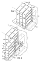
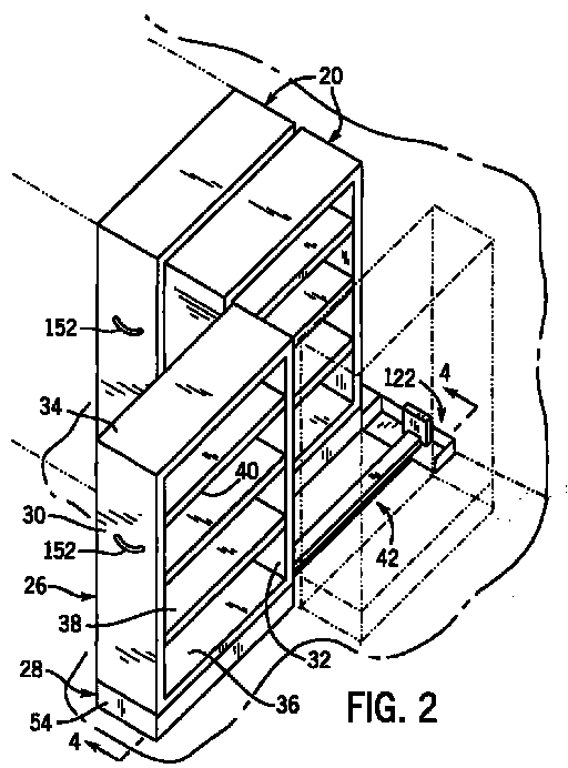
- Fig. 1 illustrates a series of storage units or assemblies 20 mounted adjacent a wall 22 and supported by a floor or other supporting surface 24.
- each storage assembly 20 is shown in a retracted position, in which a side of each storage assembly 20 is located adjacent wall 22.
- Storage assemblies 20 are located immediately adjacent each other, and are typically installed in a row of numerous similarly constructed storage assemblies 20, to provide high density storage along wall 22.
- Each storage assembly 20 is movable between a refracted position and an extended position.
- Storage assemblies 20 of Fig. 1 are shown in the refracted position, and the endmost one of storage assemblies 20 in Fig. 2 is illustrated as being moved to its extended position.
- Each storage assembly 20 is in the form of a storage cabinet 26 mounted to a base 28, in a manner to be explained.
- Storage cabinet 26 is of conventional construction, including a pair of spaced sides 30, 32, a top 34, and a bottom 36 which cooperate to define an internal storage space 38 which may be subdivided using a series of shelves 40.
- Storage cabinet 26 has an open front which provides access to internal storage space 38, and is preferably closed at its rear. When one of storage cabinets 26 is in its extended position as shown in Fig. 2, internal storage space 38 is fully exposed so as to provide access to items stored on shelves 40. When retracted, storage cabinets 26 are located immediately adjacent each other without aisles therebetween, such that the front of each storage cabinet 26 can only be accessed by moving the storage cabinet 26 to its extended position.
- each storage assembly 20 is illustrated as including an open front storage cabinet 26, it is understood that other types of storage members, such as file cabinets or storage cabinets with doors, may be incorporated into storage assembly 20.
- Each storage cabinet 26 extends along a longitudinal axis, along which the storage cabinet 26 is movable between its extended and retracted positions, in a manner to be explained.
- the open front of each storage cabinet 26 opens in a direction transverse to the longitudinal axis.
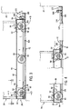
- Figs. 3-5 illustrate base 28 and an extendible and retractable guide assembly 42 which interacts with base 28 to guide movement of storage cabinet 26 between its extended and retracted positions.
- base 28 includes a pair of wheel-mounting channel members 44, each of which includes an inner wall 46, and outer wall 48 and a top wall 50 extending between and interconnecting the upper ends of inner and outer walls 46, 48, respectively.
- Channel members 44 extend throughout the length of base 28, and are interconnected at their ends via a pair of transverse upper plate members 52, which overlie top wall 50.
- Each upper plate member 52 is bent downwardly at its outer end outwardly of the ends of channel members 44, to form an outer wall 54, and is bent downwardly at its inner end between the facing inner surfaces of channel members 44 to form a lip 56 (Fig. 15).
- Upper plate members 52 are interconnected with channel members 44 in a manner to be explained.
- a series of wheel assemblies 58 are mounted to each channel member 44. As shown in Fig. 3, an inner wheel assembly 60 is located adjacent the inner end of each channel member 44, an outer wheel assembly 58 is located adjacent the outer end of each channel member 44, and an intermediate wheel assembly 58 may be located substantially at the center of each channel member 44.
- Each wheel assembly 58 includes a wheel member 60 mounted to an axle assembly 62, which is in the form of a threaded stud having a shank which extends through an opening in the center of wheel member 60, with a bearing being interposed between the shank and the wheel in a manner as is known. Stud 62 defines a head 64 at one end and a nut 66 is engaged with threads defined by the shank of stud 62 opposite head 64.
- Axle assembly 62 is mounted to and extends between inner and outer walls 46, 48, respectively, of channel member 44. The lower end of outer wall 48 is located closely adjacent floor 24, to enclose the interior of base 28.
- a mounting and engagement channel 70 is mounted to each upper plate member 52.
- Channel 70 includes a bottom wall 72 and a pair of side walls 74 which extend upwardly from the outer ends of bottom wall 72.
- Each side wall 74 defines an upper end in the form of a mounting tab 84, which extends through a slot 86 formed in upper plate member 52, and is welded to the upper surface of upper plate member 52 where mounting tab 84 protrudes from slot 86.
- mounting and engagement channel 70 is rigidly secured to upper plate member 52.
- Mounting and engagement channel 70 is oriented such that its side walls 74 are spaced inwardly from the inner wall 46 of each wheel-mounting channel member 44, and such that its bottom wall 72 is spaced above floor 24.
- each mounting tab 84 includes a slot 88 extending inwardly from one of its side edges, such as 90.
- Slot 88 has a laterally opening entrance 92, and is defined by a downwardly angled upper edge 94 which angles downwardly and inwardly from entrance 92, in combination with a straight bottom edge 96.
- An end edge 98 extends upwardly from the inner end bottom edge 96, and an arcuate detent edge 100 extends between end edge 98 and upper edge 94.
- the intersection of arcuate detent edge 100 and upper edge 94 defines a point of intersection 102.
- storage cabinet 26 includes a pair of corner posts, shown generally at 104, 106 between which an end wall 107 extends.
- a pair of facing, lower frame members 108 form a part of the structure of cabinet 26, and are interconnected with corner posts 104, 106 toward the lower ends of posts 104, 106.
- Lower frame members 108 face in opposite directions, and each includes an outer leg 110 and an inner leg 112, with a bight 114 extending between the lower ends of outer and inner legs 112, 114 respectively.
- the lower downwardly facing surface of bight 114 is spaced slightly above the lower ends of corner posts 104, 106.
- Storage cabinet 26 is placed on base 28 such that mounting tabs 84 are located between storage cabinet lower frame members 108 and each post 104, 106 is located directly over one of wheel assemblies 58. In this manner, the weight of storage cabinet 26 is transferred directly to floor 24 through wheel assembly 58.
- a locking rod 118 is engaged with mounting tabs 84 and lower frame members 108 for releasably mounting storage cabinet 26 to base 28.
- Fig. 6 illustrates storage cabinet 26 placed on base 28 such that the bight 114 of lower frame member 108 is spaced slightly above the upper surface of each upper plate member 52 when the lower ends of posts 104, 106 engage upper plate member 52.
- Slot 88 and base mounting tabs 84 are positioned such that, when storage cabinet 26 is engaged with base 28 in this manner, the upper edge of inner leg 112 of each frame member 108 is in alignment with the lower area of slot entrance 92 and is located above bottom edge 96 of slot 88.
- Locking rod 118 is then positioned between lower frame members 108 such that each end of locking rod 118 overlies and engages one of inner legs 112.
- Locking rod 118 has a length slightly less than the spacing between the facing surfaces of lower frame member outer legs 110, to enable locking rod 118 to be positioned in this manner.
- each upper plate member 52 includes a pair of openings 119, each of which is located adjacent one of mounting tabs 84.
- Each opening 119 includes an inner pair of spaced engagement edges 120a, 120b and an outer pair of spaced engagement edges 121a, 121b. Openings 119 are located under locking rod 118 and are generally in alignment with slots 88 in mounting tabs 84.
- the user To engage locking rod 118 with lower frame members 108 to mount storage cabinet 26 to base 28, the user initially places the ends of locking rod 118 on the upper edges of inner legs 112 of lower frame members 108 and moves locking rod 118 toward entrance 92 of slot 88 in each mounting tab 84.
- the user then engages the tip of an elongated tool, such as a screwdriver, with inner edge 120a of each opening 119, and uses the tool as a lever to engage locking rod 118 and to advance locking rod 118 in slot 88.
- an elongated tool such as a screwdriver
- the user disengages the tool from edge 120a and uses edge 121a in the same manner to advance locking rod 118 into slot 88 in each mounting tab 84.
- the user alternates between openings 119, to incrementally advance both sides of locking rod 118 in slot 88 of each mounting tab 84. This inward movement of locking rod 118 in slot 88 results in locking rod 118 riding along downwardly angled upper edge 94 of slot 88.
- detent edge 100 The elevation of detent edge 100 relative to flanges 116 is such that locking rod 118 is slightly deflected downwardly in its center relative to its outer ends which overlie flanges 116, such that a downward clamping force is exerted on lower frame members 108 of storage cabinet 26 toward base 28.
- locking rod 118 Once locking rod 118 passes intersection 102 upon inward movement into slot 88, locking rod 118 snaps into the recess defined by detent edge 100 and maintains engagement with detent edge 100.
- the user reverses the above steps using an elongated tool and edges 120b, 121b, to disengage locking rod 118 from the recess defined by detent edge 100 and to move locking rod 118 through slot 88 in an outward direction. It can thus be appreciated that provision of mounting tabs 84 with slots 88 formed therein, along with locking rod 118, provides an efficient and convenient method for removably mounting storage cabinet 26 to base 28.
- Figs. 5 and 8-10 illustrate the means by which base 28 is interconnected with guide assembly 42 for guiding movement of base 28 for moving storage cabinet 26 between its extended position of Fig. 2 and its retracted position of Fig 1.
- guide assembly 42 includes an inner mounting member 122 (Figs. 3, 4) and a mounting rail 124 mounted to and extending outwardly from inner mounting member 122.
- Mounting rail 124 is in the form of an inverted channel having side walls 128 and a top wall 130 which extends between the upper ends of side walls 128.
- a slide mechanism 132 is mounted to mounting rail top wall 130.
- slide mechanism 132 includes a guide track 134 which is secured to mounting rail top wall 130, and a telescoping slide member 136 which is movably mounted to guide track 134 and which is interconnected with base 28, in a manner to be explained.
- Guide track 134 is fixed in position on mounting rail 124, and slide member 136 is preferably in the form of a telescoping extendible and retractable member slidably mounted within track structure defined by guide track 134.
- Ball bearings are interposed between the components of slide mechanism 132 which are moveable relative to each other, to facilitate extension and retraction of slide member 136 relative to guide track 134.
- slide mechanism 132 may be a heavy duty drawer slide such as is available from Schock Metallwerk GmbH, Siemenstrasse 1-3, P.O. Box 1120, D-73565, Urbach, Germany, under its designations 037.07466, 037.07467, 037.07468 and 037.07360, although it is understood that any satisfactory extension and retraction mechanism could be employed.
- Figs. 5 and 8-10 also show interconnection of base 28 with slide mechanism 132. As shown, bottom wall 72 of mounting and engagement channel 70 is located slightly above the top surface of slide member 136. A cylindrical engagement member 138 is interconnected between bottom wall 72 and slide member 136.
- Bottom wall 80 defines an opening 140 and engagement member 138 extends though opening 140.
- Engagement member 138 is in the form of an upstanding cylindrical sleeve 141 interconnected with slide member 136.
- Sleeve 141 defines a vertical passage and a stud 142, which includes a head 144 and a shank 146, is mounted to slide member 136 such that the lower end of shank 146 extends though an opening formed in an upper wall of slide member 136 and the upper portion of shank 146 extends through the vertical passage in sleeve 141.
- a washer 148 rests on the top of sleeve 141, and a nut 150 is engaged with the threaded end portion of shank 146 so as to secure sleeve 141, stud 142, washer 148 and nut 150 to slide member 136 as a unit.
- Opening 140 in lower wall 72 has a diameter less than that of washer 148, so as to provide "floating" vertical movement between engagement member 138 and bottom wall 72 of mounting and engagement channel 70.
- Washer 148 functions as an upper stop and slide member 136 functions as a lower stop, to control the range of relative movement between engagement member 138 and bottom wall 72.
- engagement member 138 is fixed to slide member 136 so as to be movable therewith relative to guide track 134.
- Engagement member 138 which extends through opening 140 in bottom wall 72 of mounting and engagement channel 70, functions to interconnect base 28 with slide member 136.
- the user exerts an axial pull-out or push-in force on storage cabinet 26, typically by use of a handle 152 (Figs. 1, 2) mounted to the outer side 30 of storage cabinet 26.
- This force is transferred to base 28, which causes wheel members 60 to rotate so as to move storage cabinet 26 on floor 24.
- This movement of base 28 is transferred to slide mechanism 132 by engagement of engagement member 138 with the edges of opening 140 formed in mounting and engagement channel 70, such that slide mechanism 132 extends and retracts in response to the pull-out or push-in movement of storage cabinet 26.
- the total range of vertical movement between slide mechanism 132 and base 28 is defined by the space between the upper surface of slide member 136 and the underside of washer 148, which function to ensure that bottom wall 80 is trapped therebetween to maintain engagement of base 28 with slide mechanism 132.
- inner mounting member 122 defines a bottom plate 158, adapted for engagement with floor 24, and an end wall 160 extending upwardly from the inner end of bottom plate 158.
- a series of openings 162 are formed in bottom plate 158, and anchor bolts, which are secured to floor 24, extend upwardly through selected ones of openings 162.
- a nut, such as shown at 163, is engaged with the threaded shank of each anchor bolt, so as to securely mount inner mounting member 122 to floor 24.
- end wall 160 of inner mounting member 122 is engaged with wall 22, which extends upwardly from floor 24.
- the inner end of mounting rail 124 overlies bottom plate 158 and is secured thereto such as by welding.
- the end of mounting rail 124 abuts the outer surface of a stop plate 164, and is secured thereto such as by welding.
- a reinforcing plate 165 extends between stop plate 164 and end wall 160, and is secured in place such as by welding.
- Inner mounting member 122 further includes a pair of side flanges 166, which are preferably formed of upwardly bent end sections of bottom plate 158.
- a resilient bumper 168 is mounted to stop plate 164 via a bolt 170, which extends though an opening formed in stop plate 164, and a nut 172 is engaged with bolt 170 so as to securely mount bumper 168 to stop plate 164.
- a number of inner mounting members 122 are placed side-by-side at the corner defined by wall 22 and floor 24.
- the side flanges 166 of adjacent inner mounting members 122 are placed in engagement with each other and openings in side flanges 164 are in alignment with each other, such that the shank of a bolt 174 (Fig. 14) is placed through the aligned openings.
- a nut 176 engages the shank of bolt 174 and, in this manner, adjacent inner mounting members 122 are secured to each other.
- Inner mounting member 122 functions to secure the inner end of mounting rail 124 in position on floor 24.
- the outer end of mounting rail 124 is connected to an angle member 177, which includes a horizontal flange secured to floor 24 using conventional anchor bolts. In this manner, both the outer and inner ends of mounting rail 124 we fixed in position on floor 24.
- Angle member 177 further includes a vertical flange to which a resilient bumper 178 is mounted via a bolt and nut assembly, shown generally at 179.
- a catch member 180 is mounted toward each of the inner and outer ends of mounting rail 124, and catch members 180 we mounted on opposite sides of mounting rail 124.
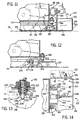
- a pair of retainer mechanisms shown generally at 182 (Fig. 5 and 11-14), are mounted to base 28 adjacent its inner end. In a manner to be explained, each retainer mechanism 182 is releasably engageable with one of catch members 180 so as to releasably retain storage cabinet 26 in either its extended or retracted position.
- each catch member 180 is mounted to one of mounting rail side walls 128 via a pair of fasteners 184 which extend through openings formed in a mounting section 186 of catch member 180.
- a ramped guide surface 188 is formed at the top of catch member 180, terminating in a groove 190.
- An upper horizontal rear surface extends from groove 190 in a direction opposite ramped guide surface 188.
- the innermost catch member 180 is oriented such that its ramped guide surface 188 points away from wall 22, and the outer catch member 180 is oriented in an opposite direction, such that its ramped guide surface 188 points toward wall 22.
- Each retainer mechanism 182 includes a cylindrical housing 198 having a threaded side wall 200 and an end wall 202.
- Housing 198 defines an internal cavity 204, which is closed at its upper end via a threaded plug 206.
- a retainer button 208 extends outwardly of housing 198 through an opening formed in end wall 202, and a shoulder 210 is defined at the inner end of retainer button 208. Shoulder 210 is received within cavity 204, and is sized so as to engage end wall 202 adjacent the opening through which button 208 extends, such that button 208 is slidably mounted within cavity 204.
- a spring 212 is disposed within cavity 204, bearing between the top surface of shoulder 210 and the bottom of plug 206, for biasing button 208 outwardly toward a position in which shoulder 210 engages end wall 202, as shown in solid lines in Fig. 13.
- An opening 214 is formed in a retainer mounting tab 215 which extends inwardly from the inner end wall of base 28.
- the upper end of housing sidewall 200 includes external threads which engage internal threads formed in a sleeve 216 which extends through an opening in mounting tab 215.
- Sleeve 216 defines an upper flange 217 which overlies mounting tab 215 and is welded thereto.
- Housing 198 can be turned relative to sleeve 216 to adjust its vertical position.
- a threaded nut 218 is engaged with the external threads of housing 198, and is turned down to engage the upper surface of sleeve flange 217 to lock the vertical position of housing 198 relative to sleeve 216.
- Retainer mechanism 182 is positioned such that, when button 208 is in its extended position as shown in Fig. 13, the lower end of button 208 extends vertically below the intersection of guide surface 188 with groove 190.
- each retainer mechanism 182 interacts with catch members 180 as follows to releasably retain storage cabinet 26 in either its extended position or its retracted position.
- button 208 is engaged within groove 190 in inner catch member 180.
- button 208 engages the angled front wall of groove 190, which resists outward movement of cabinet 26.
- the front wall of groove 190 functions to move button 208 upwardly within housing cavity 204, against the force of spring 212, such that the lower end of button 208 clears the intersection of guide surface 188 with groove 190 and button 208 is dislodged from groove 190.
- the lower end of button 208 then rides on guide surface 188 as outward movement of storage cabinet 26 continues.
- button 208 comes into contact with guide surface 188 of the outer catch member 180, and rides on guide surface 188 toward groove 190.
- Guide surface 188 forces button 208 upwardly against the force of spring 212.
- button 208 passes into groove 190 and returns to it extended position as shown in Fig. 13.
- a vertical stop finger 224 extends downwardly from bottom wall 72 of mounting and engagement channel 70, and engages resilient bumper 178 as storage cabinet 28 reaches its extended position. Bumper 178 acts as a cushion between base 28 and mounting rail 124.
- bumper 178 will compress an amount sufficient to enable button 208 to disengage groove 190 and pass onto rear surface 196. Bumper 178 resists such compression and tends to return to its original configuration, to move base 28 and cabinet 26 inwardly and to seat button 208 within groove 190, to releasably retain base 28 and storage cabinet 26 in its extended position. When it is desired to return storage cabinet 26 to its refracted position, an inward pushing force is exerted on storage cabinet 26 which results in engagement of button 208 with the front wall of groove 190.
- button 208 When the inward pushing force exceeds a threshold, button 208 is moved upwardly by the wall of groove 190 against the force of spring 212 and is dislodged from groove 190 defined by the outer catch member 180. This insures that a push-in force exceeding a predetermined threshold must be exerted in order to move storage cabinet 26 away from its extended position. As inward movement of storage cabinet 26 continues, button 208 engages guide surface 188 of the innermost catch member 180, which again forces button 208 upwardly into groove 190 as storage cabinet 26 reaches its retracted position. Bumper 168 cushions the impact between base 28 and stop plate 164 when storage cabinet 26 reaches its retracted position.
- bumper 168 resists compression, and bumper 168 thus urges base 28 to a position in which button 208 is engaged within groove 190, so as to ensure that a pull-out force exceeding a predetermined threshold must be exerted on storage cabinet 26 in order to move storage cabinet 26 away from its refracted position.
- Figs. 5, 15 and 16 illustrate a shim system, shown generally at 232, which is mounted to the outer one of upper plate members 52 of base 28. Shim system 232 is located in the vicinity where one of the corners of storage cabinet 26 is to be located, and a shim system 232' having minor image components is mounted toward the opposite end of upper plate member 52 from shim system 232. The following description of shim system 232 applies equally to shim system 232'.
- Shim system 232 includes a pair of upper L-shaped locating plates 234, an upper L-shaped shim member 236 and a lower L-shaped shim member 238. Locating plates 234 and upper and lower shim members 236, 238, respectively, have a similar overall configuration and footprint.
- Each locating plate 234 includes an axial leg 240 and a transverse leg 242.
- a pair of mounting apertures 244 are located toward the opposite ends of axial leg 240, and a pair of angled slots 246, 248 are formed in axial leg 240 between mounting apertures 244.
- Upper shim member 236 also includes an axial leg 250 and a transverse leg 252.
- a pair of angled end slots 254 are formed toward the opposite ends of axial leg 250, and are parallel to and in alignment with mounting apertures 244 in locating plates 234.
- An opening 256 is formed in axial leg 250 in alignment with angled slots 246 of locating plates 234, between end slots 254.
- An angled intermediate slot 258, which is parallel to end slots 254, is also located between end slots 254 and is in alignment with angled slots 248 of locating plates 234.
- Lower shim member 238 also defines an axial leg 260 and a transverse leg 262.
- a pair of angled end slots 264 are formed toward the opposite ends of axial leg 260, and are parallel to and in alignment with end slots 254 of upper shim member 236.
- An angled intermediate slot 266 is formed between end slots 264 in parallel relationship thereto, and is in alignment with opening 256 in upper shim member 236 and slots 246 of locating plates 234.
- An opening 268 is formed between end slots 264, and is located in alignment with slot 258 of upper shim member 236 and slots 248 of locating plates 234.
- a pair of upwardly extending threaded studs 270 extend through aligned openings in top wall 50 of wheel-mounting channel member 44 and upper plate member 52.
- Each stud 270 which is preferably in the form of a carriage bolt, includes a threaded shank which extends through end slots 254, 264 of upper and lower shim members 236, 238, respectively, and through mounting apertures 244 of locating plates 234.
- a nut 272 is engaged with the shank of each stud 270. Studs 270 function to mount upper plate member 52 to channel members 44, and to secure shim systems 232 in position relative to upper plate member 52 and channel members 44.
- Locating plates 234 and upper and lower shim members 236, 238, respectively, are initially engaged with upper plate member 52 in an aligned, stacked configuration.
- Transverse legs 242, 252 and 262 are configured to define a corner at which a corner of cabinet 26 is to be located when placed on base 28. If the side-to-side elevation of cabinet 26 is satisfactory, locating plates 234 and upper and lower shim members 236, 238, respectively, are left as is, and simply function to locate the corner of storage cabinet 26.
- the user slightly loosens nuts 272 to enable lower shim member 238 and upper shim member 236 to be slid transversely relative to locating plates 234.
- the user inserts the tip of a tool such as a screwdriver though angled slots 248 of locating plates 234 and though angled slot 258 of upper shim member 236, into engagement with opening 268 of lower shim member 260.
- the user exerts a transverse force on the tool, which is applied to lower shim member 238 and which functions to move lower shim member 238 laterally outwardly relatively to locating plates 234 and upper shim member 236.
- Slots 248 and 258 accommodate movement of the tool as lower shim member 238 is moved outwardly, and angled end slots 264 of lower shim member 238 provide movement of lower shim member 238 relative to studs 270.
- This lateral outward movement of lower shim member 238 places the outer edges of axial leg 260 and transverse leg 262 under the corner of cabinet 26, such that the lower end of cabinet post 106 rests on lower shim member 238. If lower shim member 238 provides the desired adjustment in the vertical position of the corner of cabinet 26, nuts 272 are tightened so as to secure lower shim member 238 and upper shim member 236 in position. Locating plates 234 and upper shim member 236 remain in a constant position relative to upper plate member 52, to locate the inside corner of storage cabinet 26.
- the user loosens nuts 272 while lower shim member 238 remains in its extended position.
- the user then inserts the tool tip though angled intermediate slots 246 of locating plates 234 into engagement with opening 256 of upper shim member 236.
- Slot 266 in lower shim member 238 functions to receive any portion of the tool tip which protrudes below upper shim member 236.
- the user then exerts a lateral force on the tool, which is applied to upper shim member 236 at opening 256, to move upper shim member 236 laterally relative to locating plates 234.
- FIG. 5 illustrates upper shim member 236 and lower shim member 238 moved outwardly in this manner, such that upper and lower shim members 236, 238, respectively, are positioned below the corner of cabinet 26, to raise one side or the other of cabinet 26 to a desired elevation.
- shim system 232 serves the dual purpose of locating the corners of storage cabinet 26 on base 28, as well as providing selective adjustment in the elevation of storage cabinet 26 relative to base 28.
- shim system 232 may incorporate any number of movable shim members and locating plates as desired, and is not limited to the exact numbers and configurations shown and described.
- shim systems 232, 232' are provided on the outer one of upper plate members 52 of base 28. If necessary, shim systems such as 232, 232' may also be located at the inner one of upper plate members 52 to provide the side-to-side shimming capability for the inner end of storage cabinets 26. Alternatively, locating plates 234 may be mounted to the inner one of upper plate members 52, without shim members 236, 238, to locate the inner corners of storage cabinet 26 on base 28.
- locking rod 118 flexes when engaged within slot 88 so as to securely clamp storage cabinet 26 onto base 28.
- the flexibility of locking rod 118 is sufficient to accommodate use of one or both of upper and lower shim members 236, 238 when positioned between storage cabinet 26 and base 28.
- storage assembly 20 provides a simple and efficient construction for a floor-supported extendible and retractable storage cabinet.
- the storage cabinet is adapted for mounting to a compact and efficiently arranged wheeled base via a mounting arrangement providing quick and easy mounting of the storage cabinet to the base using a minimal number of tools.
- the guide mechanism which guides movement of the base so as to move the storage cabinet between its extended and retracted positions, adapts existing drawer slide technology in a floor-mounted application so as to guide movement of the base.
- a unique floating engagement structure is interposed between the guide assembly and the base for accommodating unevenness in the floor and for minimizing stress on the guide components as the base is moved between its extended and retracted positions.
- a relatively simple and effective retainer mechanism ensures that the storage cabinet is releasably retained in either its extended or retracted position so as to prevent inadvertent movement of the storage cabinet away from either position.
- a simple and easily operated shim system functions to both locate the cabinet on the base and to adjust the elevation of the cabinet relative to the base.
- One embodiment is a storage assembly adapted for movement relative to a supporting surface between first and second positions, which comprises a storage member including a pair of spaced surfaces located toward a lower end defined by the storage member, and a base including a set of rotatable wheels for engagement with the supporting surface to provide movement of the storage member thereon.
- a removable mounting arrangement interposed between the base and the storage member, comprising a locking slot associated with the base and defining a laterally facing entrance, a locking slide located between the pair of spaced surfaces defined by the storage member; and a locking member releasably engageable within the locking slot and defining a pair of spaced engagement surfaces located one on either side of the locking slot, wherein each engagement surface is adapted to overlie one of the spaced surfaces of the storage member and wherein the locking slot is configured such that movement of the locking member in the locking slot inwardly of the entrance is operable to move the engagement surfaces of the locking member into contact with the spaced surfaces of the storage member to maintain engagement of the storage member with the base.
- a guide assembly for guiding movement of the storage member between the first and second positions
- the guide assembly includes an inner mounting member adapted to be secured to the supporting surface; and an axially telescoping slide assembly interposed between the inner mounting member and the base, including a fixed-position guide member mounted to and extending from the mounting member, and an axially movable extension member interconnected with the guide member and the base, wherein the guide member and the extension member are operable to guide movement of the storage member between the first and second positions; engagement structure is interposed between the base and the extension member, wherein the engagement structure is constructed and arranged to accommodate relative vertical movement between the base and the extension member as the storage member is moved between the first and second positions; and further there is a retainer mechanism for releasably maintaining the storage member in the first position, comprising a catch member mounted to one of the base and the inner mounting member, and a movable retainer member mounted to the other of the base and the inner mounting member, wherein the catch member includes an engagement surface with which
- This embodiment further includes a shim system for altering the elevation of the storage member relative to the base, the system comprising two or more shim members mounted to the base via a mounting arrangement which provides fixed-position mounting of a first one of the shim members relative to the base and movable mounting of a second one of the shim members relative to the first shim member and relative to the base, wherein the second shim member is located between the first shim member and the base and is movable between a shimming position in which the second shim member is positioned between the storage member and the base, and a withdrawn position in which the second shim member is withdrawn from between the storage cabinet and the base to provide direct engagement of the storage cabinet with the base.
- a shim system for altering the elevation of the storage member relative to the base, the system comprising two or more shim members mounted to the base via a mounting arrangement which provides fixed-position mounting of a first one of the shim members relative to the base and movable mounting of
- FIG. 1 Another embodiment is a storage assembly adapted for movement relative to a supporting surface between a first position and a second position, the assembly comprising a storage member having a base located at its lower end, a guide assembly for guiding movement of the storage member during movement between the first and second positions, the guide assembly including an inner mounting member adapted to be secured to the supporting surface, and an axially telescoping slide assembly interposed between the inner mounting member and the storage member base, including a fixed-position guide member mounted to and extending from the mounting member, and an axially movable extension member interconnected with the guide member and the storage member base, wherein the guide member and the extension member are operable to guide movement of the storage member between the first and second position.
- the base can include a set of rotatable wheels for engagement with the supporting surface to provide movement of the storage member thereon between the first and second positions.
- the guide assembly can further include a mounting rail secured to and extending from the inner mounting member and engageable with the supporting surface, wherein the fixed-position guide member is secured to the mounting rail.
- the base can be interconnected with the axially movable extension member by means of engagement structure, interposed between the base and the extension member, which is operable to accommodate relative vertical movement between the base and the extension member as the storage member is moved between the first and second positions.
- the storage member can comprise a storage cabinet releasably mounted to the base, the base including an upper wall and a pair of depending side walls, and having a set of rotatable wheels which includes at least a pair of wheels located one adjacent each dependent side wall, each wheel being rotatably mounted to wheel mounting structure interconnected with an upper wall of the base; the mounting rail, the fixed-position guide member and the extension member can all be located between the pair of wheels.
- a further embodiment is a storage assembly adapted for movement relative to a supporting surface between first and second positions, the assembly comprising a storage member including a base having a movable supporting arrangement engaged with the supporting surface for supporting the base on the supporting surface and providing movement of the base between the first and second positions, a guide arrangement interconnected with the supporting surface for guiding movement of the base between the first and second positions; and engagement structure interposed between the base and the guide arrangement, wherein the engagement structure is constructed and arranged to accommodate relative vertical movement between the base and the guide arrangement as the base is moved between its first and second positions.
- the guide arrangement can here comprise a fixed-position guide member interconnected with the supporting surface and an axially movable extension member interconnected with the fixed-position guide member and with the storage member base, wherein the engagement structure is interconnected between the base and the extension member.
- the engagement structure in this embodiment comprises an opening associated with the base and an engagement member mounted to the extension member and extending into the opening, wherein the engagement member is vertically movable within the opening to accommodate relative vertical movement between the base and the guide arrangement as the base is moved between the first and second positions.
- This opening can be formed in a horizontal wall associated with the base, and wherein the engagement member includes a pair of vertical engagement surfaces extending upwardly from the extension member, wherein each upstanding engagement surface is located adjacent an edge of the horizontal wall defining the opening, wherein the engagement member is vertically movable within the opening and wherein engagement of each engagement surface with the adjacent edge of the horizontal wall defining the opening is operable to engage the base with the extension member.
- the engagement member defines a central mounting section adapted for removable mounting to the extension member, and wherein the pair of vertical engagement surfaces are defined by a pair of end members, each of which is interconnected with and extends upwardly from the central mounting section.
- Still another embodiment is a storage assembly adapted for movement relative to a supporting surface between a first position and a second position, the assembly comprising a storage member having a base located at its lower end, wherein the base includes a movable supporting arrangement engaged with the supporting surface for supporting the storage member on the supporting surface and providing movement of the storage member between its first and second positions; a guide assembly for guiding movement of the storage member during movement between the first and second positions, wherein the guide assembly includes a mounting member adapted to be secured to the supporting surface, and a guide member secured to and extending from the mounting member and interconnected with the base; and a retainer mechanism for releasably maintaining the storage member in its first position, comprising a catch member mounted to one of the base and the guide assembly, and a movable retainer member mounted to the other of the base and the guide assembly, wherein the catch member includes an engagement surface with which the movable retainer member is engageable to maintain the storage member in its first position, wherein the retainer member is movable out of engagement with
- the base can include a set of rotatable wheels for engagement with the supporting surface to provide movement of the storage member thereon between the first and second positions
- the guide member comprises an axially telescoping slide assembly interposed between the mounting member and the base, including a fixed-position guide member mounted to and extending from the mounting member, and an axially movable extension member interconnected with the fixed-position guide member and the base, wherein axial movement of the extension member relative to the guide member is operable to guide movement of the storage member between the first and second positions.
- the catch member can include a ramped surface extending from the engagement surface, wherein the movable retainer member is engageable with the ramped surface for guiding the movable retainer member into engagement with the engagement surface as the storage member is moved toward its first position.
- the movable retainer member can be movably mounted to a housing for movement between an outward position and an inward position, and further comprising a biasing element interposed between the housing and the retainer member for biasing the retainer member toward its outward position.
- movement of the storage member toward its first position can cause engagement of the retainer member with the ramped surfaced to move the retainer member toward its inward position against the force of the biasing element, and wherein movement of the retainer member past the engagement surface as the storage member is moved to its first position can result in movement of the retainer member toward its outward position under the influence of the biasing element.
- the catch member can be mounted to the mounting member and the movable retainer member and housing are mounted to a lower wall defined by the base which overlies at least a portion of the mounting member when the storage member is in the first position.
- the storage assembly can further comprise a resilient bumper interposed between the mounting member and the base for cushioning impact between the storage member and the base when the storage member is moved to the first position.
- Another inventive embodiment of the present development is a system for altering the position of a first member relative to a second member, comprising a shim arrangement mounted to the first member for movement while mounted to the first member between a shimming position in which at least a portion of the shim arrangement is interposed between and engaged with the first and second members, and a withdrawn position in which the shim arrangement is withdrawn from between the first and second members to provide direct engagement of the first and second members with each other, wherein the shim arrangement includes locating structure in a predetermined constant location on the first member both when the shim arrangement is in its shimming position and when the shim arrangement is in its withdrawn position, for cooperating with the second member to locate the second member relative to the first member.
- the first member can be an article of furniture and the second member can be a base structure adapted to support the article of furniture.
- the article of furniture can comprise a storage member and the base structure can comprise a movable base member for providing movement of the storage member between an extended position and a retracted position.
- the shim arrangement can comprise an upper locating member and a lower shim member located between the base member and the upper locating member, the upper locating member being mounted in a fixed position to the base member and the lower shim member being movably mounted to and between the base member and the upper locating member.
- the upper locating member can be mounted in a fixed position to the base member via one or more openings in the upper locating member and one of more fasteners which extend through the one or more openings into engagement with the base member, and the lower shim member can be movably mounted via slot structure formed in the lower shim member and through which the one or more fasteners extend for providing movement of the lower shim member relative to the base member and the upper locating member while the one or more fasteners are in place.
- the lower shim member may be laterally movable relative to the upper locating member to displace the lower shim member so that a shimming surface defined by the lower shim member is exposed when the lower shim member is moved laterally relative to the upper locating member so as to place the shim arrangement in its shimming position.
- the upper locating member can include a slot and the lower shim member can includes an opening with the slot, wherein a tool is adapted for passage through the slot for engagement within the opening in the lower shim member, such that application of a transverse force to the tool engages the tool with an edge of the opening to move the lower shim member so as to place the shim arrangement in its shimming position, wherein the slot in the upper locating member accommodates transverse movement of the tool.
Landscapes
- Engineering & Computer Science (AREA)
- Mechanical Engineering (AREA)
- Legs For Furniture In General (AREA)
- Casings For Electric Apparatus (AREA)
- Drawers Of Furniture (AREA)
Abstract
Description
Claims (23)
- A storage assembly adapted for movement relative to a supporting surface between first and second positions, comprising:a storage member having a base located at its lower end, wherein the base includes a set of rotatable wheels for engagement with the supporting surface to provide movement of the storage member thereon; anda guide assembly for guiding movement of the storage member between the first and second positions, comprising a mounting member adapted to be secured to the supporting surface, and an extendible and retractable guide mechanism interposed between the mounting member and the storage member for guiding movement of the storage member between its first and second positions.
- The storage assembly of claim 1, wherein the cabinet and base extend along a horizontal longitudinal axis, and wherein the storage member defines an internal storage area which opens in a direction transverse to the longitudinal axis, wherein the guide assembly is constructed and arranged to provide movement of the storage member and base along the horizontal longitudinal axis between the first and second positions.
- The storage assembly of claim 2, wherein the storage member comprises a cabinet releasably engaged with the base.
- The storage assembly of claim 3, wherein the cabinet defines a lower end engageable with the base and includes a pair of spaced members located at its lower end, and wherein the cabinet is releasably engaged with the base by means of an engagement member which spans between and engages the spaced members of the cabinet, wherein the engagement member is releasably engaged with engagement structure provided on the base which is operable to force the engagement member against the pair of spaced members of the cabinet.
- The storage assembly of any of claims 1 to 4, wherein the base includes an upper wall and a pair of spaced side walls extending downwardly from the upper wall, wherein the upper wall and side wall define an interior, and wherein the set of rotatable wheels comprises a pair of spaced wheels, each of which is rotatably mounted to wheel mounting structure secured to an underside defined by the top wall of the base and located within the interior of the base.
- The storage assembly of any of claims 1 to 5, wherein the extendible and retractable guide mechanism comprises a telescoping slide arrangement interconnected between the mounting member and the base.
- The storage assembly of claim 6, wherein the guide assembly further includes a mounting rail secured to the mounting member and engageable with the supporting surface, wherein the telescoping slide arrangement is mounted to the mounting rail.
- The storage assembly of claim 5, 6 or 7, wherein the cabinet defines a pair of spaced sides, wherein the guide assembly mounting member is located outwardly of one of the sides of the cabinet, wherein the mounting rail and the telescoping slide arrangement extend from the mounting member beneath the cabinet and terminate in an outer end located inwardly of a second one of the sides of the cabinet.
- The storage assembly of claim 7, further comprising engagement structure interposed between the base and the telescoping slide arrangement for causing extension and retraction of the telescoping slide arrangement in response to horizontal movement of the storage member and the base on the supporting surface, and wherein the engagement structure is constructed and arranged to accommodate relative vertical movement between the base and the telescoping slide arrangement as the storage member and base are moved between the first and second positions.
- The storage assembly of claim 2, further comprising a releasable retainer mechanism interposed between the base and the guide assembly mounting member for releasably retaining the storage member in one of the first and second positions.
- The storage assembly of claim 10, wherein the releasable retainer mechanism comprises a catch member mounted to one of the base and the mounting member, and a movable retainer member mounted to the other of the base and the mounting member, wherein the catch member includes an engagement surface with which the moveable retainer member is engageable to maintain the storage member in one of the first and second positions, wherein the retainer member is movable out of engagement with the engagement surface upon application of an axial force to the storage member tending to move the storage member from its first position toward its second position to enable movement of the storage member to its second position, wherein return movement of its storage member to its first position results in subsequent engagement of the retainer member with the engagement surface to releasably retain the storage member in the first position.
- A system for removably mounting an article of furniture to a movable base, wherein the article of furniture includes a pair of spaced surfaces located toward a lower end defined by the article of furniture, comprising:locking structure associated with the base and defining a laterally facing entrance, wherein the locking structure is located between the pair of spaced surfaces; anda locking member releasably engageable within the locking structure and defining a pair of spaced engagement surfaces located one on either side of the locking structure, wherein each engagement surface is adapted to overlie one of the spaced surfaces of the article of furniture, wherein the locking structure is configured such that movement of the locking member into engagement with the locking structure inwardly of the entrance is operable to move the engagement surfaces of the locking member into contact with the spaced surfaces of the article of furniture to maintain engagement of the article of furniture with the base.
- The removable mounting system of claim 12, wherein the article of furniture comprises a storage member and wherein the pair of spaced surfaces located toward a lower end defined by the storage member are defined by a pair of spaced horizontal frame members forming a part of the storage member.
- The removable mounting system of claim 13, wherein the movable base includes an upper support surface for supporting the storage member thereabove, wherein the pair of spaced horizontal frame members of the storage member are located adjacent the upper support surface of the movable base.
- The removable mounting system of claim 14, wherein the base is movable by means of at least one set of laterally spaced wheels, wherein each wheel is rotatably mounted to wheel mounting structure interconnected with the upper support surface of the movable base and located beneath one of the pair of spaced horizontal frame members of the storage member.
- The removable mounting system of claim 13, 14 or 15, wherein the locking member comprises an elongated rod defining a pair of spaced ends, wherein each end of the locking rod overlies one of the pair of spaced horizontal frame members of the storage member.
- The removable mounting system of claim 16, wherein the locking structure comprises a locking slot defined by at least one mounting member interconnected with the upper support surface of the movable base.
- The removable mounting system of claim 17, wherein at least an upper portion of the laterally facing entrance of the locking slot is located vertically above the pair of spaced surfaces defined by the pair of spaced horizontal frame members of the storage member, and wherein the locking slot is configured such that movement of the elongated rod laterally into the locking slot moves the spaced ends of the elongated rod downwardly against the spaced surfaces defined by the pair of spaced horizontal frame members.
- The removable mounting system of claim 18, wherein the upper portion of the locking slot is defined by a downwardly angled engagement surface extending inwardly from the slot entrance, and wherein the slot further includes a detent surface located inwardly of the downwardly angled engagement surface for engaging the elongated rod and retaining the elongated rod within the slot in a position wherein the spaced ends of the elongated rod engage the spaced surfaces defined by the pair of spaced horizontal frame members of the storage member.
- A shim system for use in combination with an article of furniture and a support to which the article of furniture is adapted to be mounted, comprising two or more shim members mounted to the support by a mounting arrangement providing fixed-position mounting of a first one of the shim members relative to the support and movable mounting of a second one of the shim members relative to the first shim member and relative to the support, wherein the second shim member is located between the first shim member and the support and is movable between a shimming position in which the second shim member is positioned between the article of furniture and the support, and a withdrawn position in which the second shim member is withdrawn from between the article of furniture and the support to provide direct engagement of the article of furniture with the support.
- The shim system of claim 20, wherein the mounting arrangement comprises a pair of spaced connectors interconnected between the support and an upper one of the first and second shim members, and wherein the mounting arrangement further includes slot structure formed in a lower one of the first and second shim members through which the pair of connectors extend for providing movement of the lower shim member relative to the support and relative to the upper shim member.
- The shim system of claim 21, including a pair of lower shim members, each of which includes slot structure through which the pair of connectors extend, wherein each of the lower shim members are movable separately relative to the support and the upper shim member between the shimming and withdrawn positions.
- The shim system of claim 22, wherein the upper shim member includes first and second transverse slots, and wherein a lowermost one of the lower shim members includes an opening in alignment with the first slot and wherein an uppermost one of the lower shim members includes a slot in alignment with the opening and with the first slot, and wherein the uppermost one of the lower shim members further includes an opening spaced from the slot and in alignment with the second transverse slot in the upper shim member and wherein the lowermost one of the lower shim members includes a slot in alignment with the opening in the uppermost lower shim member and with the second slot in the upper shim member, wherein the tip of a tool is adapted to be inserted through the first and second slots in the upper shim member for engagement with the openings in the lower shim members, wherein application of a transverse force to the tool causes lateral movement of the lower shim members relative to the upper shim member, wherein the slot in the uppermost one of the lower shim members accommodates transverse movement of the tip of the tool and wherein the slot in the lowermost one of the second shim members receives a portion of the tip of the tool which projects through the opening in the uppermost one of the lower shim members to accommodate lateral movement of the lower and upper shim members, respectively.
Applications Claiming Priority (2)
| Application Number | Priority Date | Filing Date | Title |
|---|---|---|---|
| US328478 | 1981-12-08 | ||
| US09/328,478 US6416143B1 (en) | 1999-06-09 | 1999-06-09 | Mobile storage system |
Publications (2)
| Publication Number | Publication Date |
|---|---|
| EP1059050A2 true EP1059050A2 (en) | 2000-12-13 |
| EP1059050A3 EP1059050A3 (en) | 2001-04-11 |
Family
ID=23281159
Family Applications (1)
| Application Number | Title | Priority Date | Filing Date |
|---|---|---|---|
| EP00304733A Withdrawn EP1059050A3 (en) | 1999-06-09 | 2000-06-05 | Mobile storage system |
Country Status (3)
| Country | Link |
|---|---|
| US (1) | US6416143B1 (en) |
| EP (1) | EP1059050A3 (en) |
| CA (1) | CA2302927C (en) |
Cited By (11)
| Publication number | Priority date | Publication date | Assignee | Title |
|---|---|---|---|---|
| GB2359731A (en) * | 2000-02-29 | 2001-09-05 | Spacesaver Corp | Stabilising mobile storage units |
| EP1275325A1 (en) * | 2001-07-12 | 2003-01-15 | Fulterer Gesellschaft m.b.H. | Braking device for slowing down the opening or closing movement of a pull-out piece of furniture |
| EP1396212A1 (en) * | 2002-09-09 | 2004-03-10 | Peka-Metall Ag | Cupboard unit with drawer |
| ITBO20090239A1 (en) * | 2009-04-15 | 2010-10-16 | V E P 87 S R L | DEVICE FOR THE SUPPORT OF EXPOSABLE EXHIBITORS |
| CN103405039A (en) * | 2013-07-29 | 2013-11-27 | 海发(宁波)办公设备有限公司 | Compact shelf |
| CN109415074A (en) * | 2016-06-23 | 2019-03-01 | 威尔泰克联合股份有限公司 | Cart with removable wheel seat |
| CN111824900A (en) * | 2020-07-16 | 2020-10-27 | 张涛 | Logistics household system |
| US11473719B2 (en) | 2014-12-24 | 2022-10-18 | Veltek Associates, Inc. | Stationary transfer platform and cleaning device for supply transport device |
| US20230173985A1 (en) * | 2021-12-02 | 2023-06-08 | Ford Global Technologies, Llc | Rack system for a commercial vehicle and commercial vehicle |
| USD1047340S1 (en) | 2015-12-22 | 2024-10-15 | Veltek Associates, Inc. | Wheel base assembly |
| US12280743B2 (en) * | 2021-12-15 | 2025-04-22 | Ford Global Technologies, Llc | Automobile with rack in the cargo space |
Families Citing this family (21)
| Publication number | Priority date | Publication date | Assignee | Title |
|---|---|---|---|---|
| FR2822770B1 (en) * | 2001-03-30 | 2003-08-15 | Sai Automotive Allibert Ind | DEVICE INCLUDING A REMOVABLE SLIDING CENTER CONSOLE |
| US20040029617A1 (en) * | 2002-08-08 | 2004-02-12 | Mpf Technologies, Inc. | Track system for telecommunications transmission stations |
| US20040219924A1 (en) * | 2003-04-29 | 2004-11-04 | Mpf Technologies, Inc. | Systems and methods for optimizing a wireless communication network |
| US7513385B2 (en) * | 2003-06-27 | 2009-04-07 | Powerwave Technologies, Inc. | Air lock cover vent for telecommunications equipment |
| US8275417B2 (en) * | 2003-06-27 | 2012-09-25 | Powerwave Technologies, Inc. | Flood evacuation system for subterranean telecommunications vault |
| US7370587B2 (en) * | 2004-12-14 | 2008-05-13 | Spacesaver Corporation | Modular wheel assembly for a carriage in a mobile storage system |
| US7770259B2 (en) * | 2005-05-04 | 2010-08-10 | Spacesaver Corporation | Suspension-type storage unit |
| DE102005028674A1 (en) * | 2005-06-21 | 2006-12-28 | BSH Bosch und Siemens Hausgeräte GmbH | Telescopic pull-out unit for a domestic appliance, e.g. a pull-out oven, has a catch unit to hold a telescopic rail in the retracted position to prevent an uncontrolled movement |
| US20070278914A1 (en) * | 2006-05-23 | 2007-12-06 | Guy Verfaillie | Closet pull-out organizer cabinet |
| WO2010078677A1 (en) * | 2008-12-30 | 2010-07-15 | Pan Huilan | Storage assembly |
| TWI439205B (en) * | 2011-08-30 | 2014-05-21 | Hon Hai Prec Ind Co Ltd | Rack mechanism for server |
| MA40401A (en) * | 2014-07-08 | 2017-05-24 | Rail Veyor Tech Global Inc | CONTROL SYSTEM FOR AN IMPROVED RAIL TRANSPORTATION SYSTEM FOR TRANSPORTING BULK MATERIALS |
| CA3028485A1 (en) * | 2014-12-24 | 2016-06-30 | Veltek Associates, Inc. | Cart with removable wheel base |
| US9994244B2 (en) * | 2014-12-24 | 2018-06-12 | Veltek Associates, Inc. | Cart with removable wheel base |
| US10830104B2 (en) * | 2016-10-27 | 2020-11-10 | General Electric Company | Exhaust collector railing removal tool |
| JP6891708B2 (en) * | 2017-07-31 | 2021-06-18 | 日本電気株式会社 | Rack fixing device and server rack |
| CN110962898B (en) * | 2019-12-17 | 2021-12-31 | 深圳市世纪本原科技股份有限公司 | WIFI router transfer device |
| CN112265789B (en) * | 2020-11-12 | 2025-06-13 | 潍坊星美生物科技股份有限公司 | A kind of automatic transfer vehicle for breeding racks |
| US11993196B2 (en) * | 2021-10-14 | 2024-05-28 | Adrian Steel Company | Shelf system |
| CN114831452B (en) * | 2022-04-08 | 2022-12-23 | 宿迁学院 | Storing detection device based on intelligence cabinet |
| CN115721107B (en) * | 2022-11-10 | 2025-04-01 | 青海盐湖工业股份有限公司 | Filing Cabinets |
Family Cites Families (60)
| Publication number | Priority date | Publication date | Assignee | Title |
|---|---|---|---|---|
| US1321167A (en) | 1919-11-11 | Drawer-carrier | ||
| US2162318A (en) | 1937-01-12 | 1939-06-13 | Globe Wernicke Co | Drawer suspension |
| US2684277A (en) | 1951-10-12 | 1954-07-20 | Chrysler Corp | Multiple level filing cabinet |
| US3080204A (en) | 1958-10-14 | 1963-03-05 | Lindhgren Per Harald | Storage apparatus |
| GB1062752A (en) * | 1963-07-08 | 1967-03-22 | Austin Hoy & Co Ltd | Improvements in cutter tools and tool-boxes therefor |
| US3423781A (en) * | 1967-10-25 | 1969-01-28 | Harry H Henson | Securement for mop or broom heads |
| CA1086841A (en) | 1970-03-17 | 1980-09-30 | Han-Ichiro Naito | Shiftable article storage device |
| US3640595A (en) * | 1970-05-06 | 1972-02-08 | Staller Cabinet Inc | Motorized mobile shelving units |
| US3957323A (en) | 1970-09-02 | 1976-05-18 | Estey Corporation | Storage means with sequentially shiftable units |
| US4017131A (en) | 1970-09-22 | 1977-04-12 | J. Gestle, Ag | Maximum density mobile storage system |
| US3865446A (en) | 1972-12-04 | 1975-02-11 | Estey Corp | Storage means with shiftable units |
| US4033649A (en) | 1974-04-02 | 1977-07-05 | Elecompack Company Limited | Electrically-operated shiftable article storage device |
| US3923354A (en) | 1974-11-13 | 1975-12-02 | Kidde Merchandising Equipment | Rolling shelf system |
| US4039040A (en) | 1974-11-14 | 1977-08-02 | Bar Productions (Bromsgrove) Limited | Storage assemblies |
| US3967868A (en) | 1975-02-14 | 1976-07-06 | E. Baker And Associates, Inc. | Storage system |
| US4084125A (en) | 1975-05-19 | 1978-04-11 | King James R | Mobile shelving unit |
| CA1078751A (en) | 1976-12-22 | 1980-06-03 | Elecompack Company Limited | Locking and unlocking device for manually movable wheeled storage rack or the like |
| SE402700B (en) | 1977-02-18 | 1978-07-17 | Electrolux Ab | STORAGE DEVICE |
| US4076202A (en) | 1977-03-25 | 1978-02-28 | Interlake, Inc. | Shim for rack column |
| US4123126A (en) | 1977-08-04 | 1978-10-31 | Andrew Wilson Company | Compact shelving apparatus |
| JPS5627794Y2 (en) | 1977-10-03 | 1981-07-02 | ||
| FR2426431A1 (en) | 1978-05-23 | 1979-12-21 | Petit Etienne | IMPROVEMENTS TO SHIMMING DEVICES FOR FURNITURE LEGS |
| US4417524A (en) | 1978-10-24 | 1983-11-29 | Supreme Equipment & Systems Corp. | Modular file or the like system |
| US4307922A (en) | 1980-03-13 | 1981-12-29 | Reflector-Hardware Corporation | Movable storage system |
| SE422144B (en) | 1980-06-27 | 1982-02-22 | Electrolux Constuctor Ab | LAGERANLEGGNING |
| FR2495720B1 (en) | 1980-12-04 | 1985-09-27 | Freyssinet Int Stup | ANCHORING DEVICE FOR PRE-STRESS CABLE COMPRISING A LARGE NUMBER OF STRANDS |
| US4467924A (en) | 1981-09-08 | 1984-08-28 | Stacor Corporation | Movable aisle storage system |
| US4523794A (en) * | 1983-07-15 | 1985-06-18 | Spacesaver Corporation | Lock for manual mobile storage system |
| US4597615A (en) | 1984-04-04 | 1986-07-01 | Andersen & Associates, Inc. | Storage system |
| US4621876A (en) | 1985-09-13 | 1986-11-11 | Gte Communication Systems Corp. | Equipment drawer support |
| GB2183147B (en) * | 1985-09-24 | 1989-09-20 | Samsung Electronic | Storage devices |
| CA1242522A (en) | 1986-02-24 | 1988-09-27 | Roger A. Beun | Electronic equipment drawer |
| US4657317A (en) | 1986-03-27 | 1987-04-14 | Gemma Joseph A | Storage assembly |
| GB2194781B (en) * | 1986-05-22 | 1990-10-17 | Rackline Ltd | Single track mobile storage structure. |
| US4705315A (en) | 1986-10-10 | 1987-11-10 | Cherry Kim N | Slidable storage container |
| US4759341A (en) | 1986-10-10 | 1988-07-26 | The Tappan Company | Sliding rail support system |
| US4708411A (en) | 1986-10-27 | 1987-11-24 | Spacesaver Corporation | Anti tip system |
| US4789210A (en) | 1988-01-11 | 1988-12-06 | White Home Products Inc. | Movable cabinetry system for enclosures |
| GB2225928B (en) * | 1988-11-17 | 1992-04-15 | Adelaide Shelving Supplies Pty | Mobile storage furniture |
| US5082178A (en) | 1989-02-24 | 1992-01-21 | Spacesaver Corporation | Mobile shelving apparatus |
| US5265739B1 (en) | 1989-04-26 | 1995-08-08 | Engineered Data Products Inc | Double density storage rack system for data tape cartridges |
| US5072838A (en) | 1989-04-26 | 1991-12-17 | Engineered Data Products, Inc. | Tape cartridge storage system |
| US4911507A (en) * | 1989-06-12 | 1990-03-27 | Pipp Mobile Systems, Inc. | Mobile storage system with anti-tip construction |
| US5160189A (en) | 1990-04-03 | 1992-11-03 | Automated Storage & Retrieval Systems Of America | Automatic locking device for movable shelving |
| US5205627A (en) | 1991-03-14 | 1993-04-27 | Ripp Mobile System, Inc. | Modular anti-tip lateral mobile storage system |
| US5160190A (en) | 1991-05-20 | 1992-11-03 | Automated Storage & Retrieval Systems Of America Inc. | Movable storage system with aisle monitoring apparatus |
| US5410899A (en) * | 1993-04-22 | 1995-05-02 | Tri/Mark Corporation | Retainer clip for escutcheon assembly |
| US5636750A (en) | 1993-05-10 | 1997-06-10 | Richards-Wilcox, Inc. | Method and apparatus for automatically locating an item in a movable storage system |
| US5417486A (en) | 1993-06-25 | 1995-05-23 | White Consolidated Ind Inc | Brake wedge for rail mounted cabinets |
| US5439281A (en) | 1993-08-16 | 1995-08-08 | Denstor Mobile Storage Systems Inc. | Storage system |
| US5415300A (en) | 1993-11-05 | 1995-05-16 | Krummell; John V. R. | Push-back cart storage system |
| US5435639A (en) | 1994-03-31 | 1995-07-25 | Montel | Modular rail for mobile filing and storage systems |
| US5443312A (en) | 1994-04-07 | 1995-08-22 | Schluter; Robert J. | Rack assembly for facilitating access to wall and cabinet-mounted serviceable equipment |
| US5597217A (en) | 1995-05-19 | 1997-01-28 | Hoska; Gerald R. | Anti-tip bracket for high capacity shelving |
| US5670778A (en) | 1995-08-31 | 1997-09-23 | Kardex Systems, Inc. | Presence detector for mobile storage systems |
| US6027190A (en) | 1995-09-07 | 2000-02-22 | Stewart; Edward C. | High density linear motion storage system |
| CH690018A5 (en) | 1996-03-01 | 2000-03-31 | Eku Ag | Telescopic cupboard drawer. |
| US5683155A (en) | 1996-05-01 | 1997-11-04 | Sarno; Richard L. | Hidden track file storage system |
| US5924779A (en) * | 1996-11-01 | 1999-07-20 | Wenger Corporation | Music library system |
| AT406006B (en) | 1996-12-17 | 2000-01-25 | Fulterer Gmbh | EXTENSION DEVICE FOR CUPBOARD UNITS |
-
1999
- 1999-06-09 US US09/328,478 patent/US6416143B1/en not_active Expired - Fee Related
-
2000
- 2000-03-29 CA CA002302927A patent/CA2302927C/en not_active Expired - Fee Related
- 2000-06-05 EP EP00304733A patent/EP1059050A3/en not_active Withdrawn
Cited By (16)
| Publication number | Priority date | Publication date | Assignee | Title |
|---|---|---|---|---|
| GB2359731A (en) * | 2000-02-29 | 2001-09-05 | Spacesaver Corp | Stabilising mobile storage units |
| US6688708B1 (en) | 2000-02-29 | 2004-02-10 | Spacesaver Corporation | Stabilizing and enclosure system for mobile storage units |
| GB2359731B (en) * | 2000-02-29 | 2004-05-19 | Spacesaver Corp | Stabilising and enclosure system for mobile storage units |
| EP1275325A1 (en) * | 2001-07-12 | 2003-01-15 | Fulterer Gesellschaft m.b.H. | Braking device for slowing down the opening or closing movement of a pull-out piece of furniture |
| EP1396212A1 (en) * | 2002-09-09 | 2004-03-10 | Peka-Metall Ag | Cupboard unit with drawer |
| ITBO20090239A1 (en) * | 2009-04-15 | 2010-10-16 | V E P 87 S R L | DEVICE FOR THE SUPPORT OF EXPOSABLE EXHIBITORS |
| CN103405039A (en) * | 2013-07-29 | 2013-11-27 | 海发(宁波)办公设备有限公司 | Compact shelf |
| US11473719B2 (en) | 2014-12-24 | 2022-10-18 | Veltek Associates, Inc. | Stationary transfer platform and cleaning device for supply transport device |
| US11555576B2 (en) | 2014-12-24 | 2023-01-17 | Veltek Associates, Inc. | Stationary transfer platform and cleaning device for supply transport device |
| US12571498B2 (en) | 2014-12-24 | 2026-03-10 | Veltek Associates, Inc. | Stationary transfer platform and cleaning device for supply transport device |
| USD1047340S1 (en) | 2015-12-22 | 2024-10-15 | Veltek Associates, Inc. | Wheel base assembly |
| CN109415074A (en) * | 2016-06-23 | 2019-03-01 | 威尔泰克联合股份有限公司 | Cart with removable wheel seat |
| CN109415074B (en) * | 2016-06-23 | 2021-12-07 | 威尔泰克联合股份有限公司 | Cart with removable wheel seats |
| CN111824900A (en) * | 2020-07-16 | 2020-10-27 | 张涛 | Logistics household system |
| US20230173985A1 (en) * | 2021-12-02 | 2023-06-08 | Ford Global Technologies, Llc | Rack system for a commercial vehicle and commercial vehicle |
| US12280743B2 (en) * | 2021-12-15 | 2025-04-22 | Ford Global Technologies, Llc | Automobile with rack in the cargo space |
Also Published As
| Publication number | Publication date |
|---|---|
| CA2302927A1 (en) | 2000-12-09 |
| US6416143B1 (en) | 2002-07-09 |
| EP1059050A3 (en) | 2001-04-11 |
| CA2302927C (en) | 2004-07-27 |
Similar Documents
| Publication | Publication Date | Title |
|---|---|---|
| CA2302927C (en) | Mobile storage system | |
| CA2332781C (en) | Stabilizing and enclosure system for mobile storage units | |
| US6231138B1 (en) | Cantilevered pull-out shelf system | |
| US5205627A (en) | Modular anti-tip lateral mobile storage system | |
| US6155441A (en) | Locking pin mechanism for rack and shelf systems | |
| US20040124164A1 (en) | Workroom storage system | |
| US6669314B1 (en) | Modular mobile storage system | |
| US5011240A (en) | Segmented side wall cart | |
| US20040251227A1 (en) | Workroom storage system | |
| US7147290B2 (en) | Modular workbench system | |
| US7258317B1 (en) | Pull-out display shelf | |
| WO2005049433A2 (en) | Modular storage system for logistical management of operational units | |
| WO1989006098A1 (en) | Movable cabinetry system for enclosures | |
| US11814839B2 (en) | Mobile wall including an alignment mechanism | |
| US20170151913A1 (en) | Drawer arrangements | |
| EP1545267A1 (en) | Height adjustable desk | |
| EP0517386B1 (en) | Support panel base cover | |
| CA1284114C (en) | Anti tip system | |
| US4615572A (en) | Cantilevered drawer slide arrangement | |
| US20060232174A1 (en) | Variably configurable track-type mobile shelving system | |
| US5083848A (en) | Pull-out tray for in-cabinet installation | |
| CA2452389C (en) | Cantilevered pull-out shelf system | |
| US20240164516A1 (en) | Storage system | |
| JPH049859Y2 (en) | ||
| CN121941433A (en) | Platform for arranging at least one piece of furniture or household appliance |
Legal Events
| Date | Code | Title | Description |
|---|---|---|---|
| PUAI | Public reference made under article 153(3) epc to a published international application that has entered the european phase |
Free format text: ORIGINAL CODE: 0009012 |
|
| AK | Designated contracting states |
Kind code of ref document: A2 Designated state(s): AT BE CH CY DE DK ES FI FR GB GR IE IT LI LU MC NL PT SE |
|
| AX | Request for extension of the european patent |
Free format text: AL;LT;LV;MK;RO;SI |
|
| PUAL | Search report despatched |
Free format text: ORIGINAL CODE: 0009013 |
|
| RIC1 | Information provided on ipc code assigned before grant |
Free format text: 7A 47B 88/04 A, 7B 65G 1/10 B, 7A 47B 53/02 B, 7B 62B 5/00 B |
|
| AK | Designated contracting states |
Kind code of ref document: A3 Designated state(s): AT BE CH CY DE DK ES FI FR GB GR IE IT LI LU MC NL PT SE |
|
| AX | Request for extension of the european patent |
Free format text: AL;LT;LV;MK;RO;SI |
|
| 17P | Request for examination filed |
Effective date: 20010925 |
|
| AKX | Designation fees paid |
Free format text: AT BE CH CY DE DK ES FI FR GB GR IE IT LI LU MC NL PT SE |
|
| 17Q | First examination report despatched |
Effective date: 20040128 |
|
| STAA | Information on the status of an ep patent application or granted ep patent |
Free format text: STATUS: THE APPLICATION IS DEEMED TO BE WITHDRAWN |
|
| 18D | Application deemed to be withdrawn |
Effective date: 20050104 |