EP1058415A2 - Wellenlängenzuweisung in einem Ring - Google Patents
Wellenlängenzuweisung in einem Ring Download PDFInfo
- Publication number
- EP1058415A2 EP1058415A2 EP00304662A EP00304662A EP1058415A2 EP 1058415 A2 EP1058415 A2 EP 1058415A2 EP 00304662 A EP00304662 A EP 00304662A EP 00304662 A EP00304662 A EP 00304662A EP 1058415 A2 EP1058415 A2 EP 1058415A2
- Authority
- EP
- European Patent Office
- Prior art keywords
- node
- hop
- wavelength
- max
- nodes
- Prior art date
- Legal status (The legal status is an assumption and is not a legal conclusion. Google has not performed a legal analysis and makes no representation as to the accuracy of the status listed.)
- Withdrawn
Links
Images


Classifications
-
- H—ELECTRICITY
- H04—ELECTRIC COMMUNICATION TECHNIQUE
- H04J—MULTIPLEX COMMUNICATION
- H04J14/00—Optical multiplex systems
- H04J14/02—Wavelength-division multiplex systems
- H04J14/0278—WDM optical network architectures
- H04J14/0283—WDM ring architectures
-
- H—ELECTRICITY
- H04—ELECTRIC COMMUNICATION TECHNIQUE
- H04J—MULTIPLEX COMMUNICATION
- H04J14/00—Optical multiplex systems
- H04J14/02—Wavelength-division multiplex systems
- H04J14/0227—Operation, administration, maintenance or provisioning [OAMP] of WDM networks, e.g. media access, routing or wavelength allocation
-
- H—ELECTRICITY
- H04—ELECTRIC COMMUNICATION TECHNIQUE
- H04J—MULTIPLEX COMMUNICATION
- H04J14/00—Optical multiplex systems
- H04J14/02—Wavelength-division multiplex systems
- H04J14/0227—Operation, administration, maintenance or provisioning [OAMP] of WDM networks, e.g. media access, routing or wavelength allocation
- H04J14/0241—Wavelength allocation for communications one-to-one, e.g. unicasting wavelengths
-
- H—ELECTRICITY
- H04—ELECTRIC COMMUNICATION TECHNIQUE
- H04J—MULTIPLEX COMMUNICATION
- H04J14/00—Optical multiplex systems
- H04J14/02—Wavelength-division multiplex systems
- H04J14/0287—Protection in WDM systems
- H04J14/0293—Optical channel protection
Definitions
- This invention is directed to wavelength division multiplexed (WDM) networks, and more particularly to a method of allocating the wavelengths in a dual ring.
- WDM wavelength division multiplexed
- WDM wavelength division multiplexing
- a key feature of WDM and dense WDM systems is that the discrete wavelengths form an orthogonal set of carriers which can be separated, routed, and switched without interfering with each other, as long as the total light intensity is kept sufficiently low.
- WDM the capacity of a ring can be increased in an efficient and cost effective way with minimal changes to the nodes hardware or to the automatic switching protocol (ASP).
- a WDM ring network comprises a plurality of add/drop nodes connected in a ring along two unidirectional fibers, one for each direction around the ring.
- Each add/drop node communicates with an associated edge node(s) using a number of local wavelengths (channels).
- An edge node is also referred to herein as a user node, or a local user.
- Edge nodes can be electronic or optical nodes, this is not relevant to the present invention.
- a WDM node also comprises transmitters and receivers for each wavelength, and a wavelength add/drop multiplexer (ADM).
- ADM multiplexes the local wavelengths received from the associated electronic edge node with the pass through wavelengths, before launching the multiplexed signal over the ring in the direction of interest.
- the ADM also demultiplexes the traffic received from the ring and directs it to the associated edge node and to the downstream nodes, respectively.
- a wavelength may be filtered at a node to drop traffic from the ring to the local user, and new traffic may be added on this wavelength from a local user into the ring.
- a wavelength can pass through an intermediate node so that it will be terminated at a later node of the ring.
- a unidirectional channel is created from a source node to a destination node by injecting a wavelength at the source node and dropping it the destination node. This wavelength cannot be added or dropped at any other nodes between the source and destination nodes, in this unidirectional fiber.
- a node which is not the source or destination for a certain wavelength is called herein an intermediate node.
- Multi-wavelength dual rings can be used to create a high capacity all-optical core network interconnecting several edge nodes.
- a meshed architecture is a set of parallel dual optical rings interconnecting a number of edge nodes, with each edge node accessing any of the rings.
- wavelengths are used to create channels between optical node pairs, as described above.
- the capacity of the ring may be increased by scaling up the number of nodes per ring. This architecture could be attractive for metropolitan networks, since the cost of fibers from the electronic edge nodes, which is proportional to distance, would be small.
- US Patent No. 5,751,454 (MacDonald et al., issued on May 12, 1998, and assigned to Northern Telecom Limited) discloses a wavelength allocation method for full-mesh networks with a small number of nodes. The method provides direct node to node routes, and complete transparent interconnections with extra capacity for heavy used routes on a portion of the ring. For networks with large number of nodes, this patent proposes under-connected networks with a number of accelerated, direct routes between some of the nodes.
- a WDM ring (preferably a D/WDM ring) with n add/drop nodes connected over a forward and a reverse fiber
- a method of allocating a wavelength between each pair of nodes for obtaining a fully meshed network comprising, determining an add/drop requirement N a for all nodes of the ring, a fiber requirement N f for each span of the ring and the minimum number N of wavelengths/ span, preparing a hop table with all nodes n j and all wavelengths ⁇ i for the ring and selecting an origin for the hop table by defining a node of origin and a first wavelength, if N a ⁇ N f , determining an initial hop vector comprising a set of n initial forward hop values, generating all hops for all nodes and all wavelengths using the initial hop values and recording all the hop values in the hop table, and equipping each node with wavelength-specific receivers and transmitters according to a source-destination table prepared from the hop
- This method allows a fully meshed network to be created at the optical layer when the nodes are connected, at the physical layer, in a ring.
- the method of the invention uses a minimum number of wavelengths and a same wavelength set on each fiber, with the constraint that a wavelength is used at most once on any resource (add/drop node, fiber).
- This method can be readily incorporated in an engineering tool, which significantly simplifies design of the network configuration.
- the benefits of this method are thus a reduction of the cost of optical equipment, and a simplification of the network configuration.
- Networks using wavelength routing fall into two general types: single hop, which provide routes directly between nodes; and multi-hop, in which the units of information are accessed by relaying nodes.
- Routes in single hop networks are equivalent to independent optical fiber paths, each route using a wavelength.
- multi-hop networks a signal on a route may be relayed through several nodes, a number of wavelengths being used in the process. Relaying nodes may perform a store and forward function implying optoelectronic conversion, or simply act as transparent cross-connects.
- This specification is concerned with single hop networks, and the term "hop" is used to define the number of fiber spans passed through by a respective wavelength channel.
- Figure 1 illustrates a dual ring 10 comprising ADM nodes 1, 2, 3, ..(n-1) and n . It is to be understood that in this specification the nodes are numbered consecutively, so that, for example, second node 2 is adjacent with first node 1 and third node 3 .
- the ADM nodes are connected at the physical level over two counterpropagating fibers 20 and 21 . Arrows F (forward) and R (reverse) illustrate the direction of traffic on these fibers. It is to be understood that "forward” and “reverse” are relative terms, not intended to limit the scope of the invention; other terms may be equally used for indicating that the traffic is counter-propagating in the two fibers of the ring.
- the spans, or ring sectors between two nodes are denoted on Figure 1 by letters A to E respectively.
- Each node is connected to an associated edge switch 1 ' to n ', which manipulate the add/drop wavelengths from/to a respective user.
- Figure 1 also shows three bi-directional connections, for defining some terms used in this specification.
- Nodes 1 and 3 are bidirectionally connected along a forward channel 22 on fiber 20 , and a reverse channel 22 ' on fiber 21 .
- Nodes 1 and 3 are terminal nodes for these channels, and node 2 is an intermediate node, as channels 22, 22 ' pass through node 2.
- Figure 1 also shows a bidirectional connection between nodes 1 and n-1 on forward channel 24 and reverse channel 24 ', through intermediate node n , and another bidirectional connection between adjacent nodes n and n-1 on forward channel 23 and reverse channel 23 '. It is apparent that the span between nodes n and n-1 is shared by channels 23 and 24 in the forward direction, and by channels 23' and 24 ' in the reverse direction.
- Connections 22, 22' and 24, 24 ' are two hop connections, while connection 23, 23' is a one hop connection.
- Node n of Figure 1 adds channel 23' , drops channel 23 and passes through channels 24 and 24 '. Additional wavelengths, not shown, will also be passed through node n when this node is located between the source and destination nodes.
- the number of channels (wavelengths) per span could be much higher and is limited by the current available fiber technology.
- any of channels 22 or 22 ' may take an alternate route (not shown), passing through intermediate nodes n and n-1 . Selection of one or the other of the routes depends on the particular design of the network. Nonetheless, selecting the shortest path is generally preferable in that it minimizes the number of wavelengths per fiber.
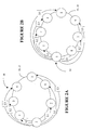
- node 1 For a ring with an odd number of nodes, there are ( n -1)/2 destinations on each unidirectional fiber.
- FIG. 2B For a ring with an even number of nodes, there are n /2 destinations on one fiber and n/2-1 on the other.
- each unidirectional fiber connects n x ( n -1)/2 source-destination pairs.
- E[ H ] the average number of hops between two nodes in a ring
- Table 1 shows these values for various odd numbers of nodes per ring. Lower bound on wavelength requirement for rings with odd numbers of nodes No. of nodes per ring (n)
- Add/drop requirement N a n -1
- Fiber requirement N f ( n 2 -1)/8 Wavelength requirement N ⁇ max ( N a , N f ) 3 2 1 2 5 4 3 4 7 6 6 6 9 8 10 10 11 10 15 15 13 12 21 21 15 14 28 28 28
- N a and N f are equal and thus every wavelength is added and dropped at each node and each wavelength is used on all unidirectional segments of the ring. Since each wavelength is used on each of the two fibers, half of the wavelengths of a unidirectional fiber are added/ dropped and the other half of the wavelengths are added/dropped on the other fiber.
- the fiber requirement is limiting for n >7, and thus all wavelengths are used on all unidirectional segments of the ring, but some wavelengths are not added/dropped at some nodes.
- the fiber requirement is limiting for n ⁇ 8.
- a wavelength allocation method is disclosed next, for a ring with an odd number of nodes, providing a fully-meshed network with the minimum number of wavelengths when the fiber requirement is the limiting constraint (i.e., for n ⁇ 7). Note that other solutions using the same number of wavelengths exist.
- the solution consists in creating, for each wavelength, a list of add/drop nodes that use the wavelength to communicate with their neighbors from the list.
- This list forms a loop: the first and last nodes are neighbors.
- each node must add and drop a wavelength only once, and thus the forward and reverse direction lists of a wavelength must consist of different nodes.
- each node must be connected to every other node.
- Wavelengths are allocated to each node of the WDM ring 10 by first preparing an allocation table (or a hop table) for both the forward and reverse directions, using the above constraints.
- a hop is denoted with h j , where j gives the starting node for the respective hop and j + h j gives the destination node.
- the initial node for a certain wavelength is denoted with j0.
- Indexes i and k are used for the range of the wavelengths; i is the range of the wavelength between 1 and N f , and k is the index for the wavelength for source-destination loops beginning at the same initial node.
- the first steps 100, 101 and 102 of the flowchart of Figure 3 are concerned with initializing i and j0, and determining if the ring has more than 6 nodes and has an odd or even number of nodes.
- n odd and greater than 6, the value for max is calculated for the respective ring in step 104 .
- Table 1 gives the number of wavelengths needed to fully connect the nodes of a ring as the maximum of N a and N f .
- max is the maximum hop for a wavelength, and is (n-1)/2.
- j0 is used as the initial node for the general case where the allocation begins at any node, not necessarily at node 1 .
- step 110 since h 1 is not max, h0 is not initialized to 1.
- ⁇ 0 is allocated to the span between the initial node and the destination node, as shown in step 116 , which means in the present case that node 1 is connected to node 2 over ⁇ 0 .
- hop Table 3 This information is recorded in hop Table 3, step 118 , and used for preparing the hop table for the reverse direction, step 120 , which is shown in detail on Figure 4 and explained in detail later.
- Step 122 illustrates how parameters are updated for the following allocations.
- h j is incremented by one for the next hop allocated from node j (using another wavelength). If a hop h j +1 is greater than max, its value is adjusted to 1 . In other words, this is a mod(h j , max)+1 operation.
- the next allocation for ⁇ i follows the same steps given above.
- wavelength ⁇ 0 hops between nodes 1, 2, 5 and back to node 1 .
- the source and destination nodes and the wavelength are recorded in a source-destination table (see Table 5), as shown in step 118 .
- the first forward connection on ⁇ 0 is terminated. This is identified by meeting condition 124 .
- steps 114-122 are repeated until j becomes j0, which indicates that the respective wavelength reached the initial node, i.e. the loop is closed.
- node 6 , ( h 6 2 ), to 1 using ⁇ 1 .
- the source-destination table is now complete for the forward direction, indicating the wavelength that connect all pair of nodes of the ring, step 134 .
- steps 114 to 124 are repeated until a certain wavelength effects a complete loop starting at node j0 and ending on node j0.
- steps 108 to 128 are repeated, until all loops having source node j0 are exhausted.
- Steps 106 to 132 are repeated until all wavelengths are allocated around the ring.
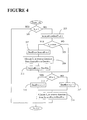
- the reverse direction is determined from the forward direction hop sequence, as shown by step 120, and illustrated in detail by the flowchart of Figure 4. Moreover, the reverse hops are determined taking into the account certain successions of hops in the forward direction.
- the method of the invention uses the following rules:
- the source node for the reverse hop denoted with SourceRvs
- SourceRvs the source node immediately before the destination node in the forward direction, DestFwd, as shown in step 203 . If SourceRvs ⁇ 0, then n is added to Source Rvs. This is done for every subsequent subtraction in the reverse direction allocation.
- the destination node for the reverse direction (DestRvd) is calculated by decreasing the SourceRvs by 1 in step 207 .
- wavelength ⁇ i is allocated in the reverse direction from the SourceRvs to the DestRvs, as shown in step 209.
- a hop of 1 takes place in the reverse direction, and SourceRvs node becomes the DestRev for the next reverse hop, step 211 .
- DestRvs node for the next hop is one node before the forward direction previous source node (hop of 1), and thus j-2 , where j is the current forward direction source node, step 215. If the forward direction previous hop h0 is different than 1, DestRvs is one node before the forward direction source node or j-1, step 217 .
- the allocation table is completed with the respective source and destination nodes for the current hop, step 219.
- Table 4 shows that the reverse direction hops do not collide with the forward direction.
- these rules are based on forward direction sequences that cover every node once and only once. Except for the second and third sequences of Table 4, each time there is a hop in the forward direction, there is the same hop in the reverse direction. The second and third sequences of Table 4 each occur max times, and together have hops of 1, max -1 and max in both directions.
- the reverse direction provides each hop from 1 to max from every node and thus connects every node to every node once and only once.
- 0 indicates wavelength ⁇ 0 in the forward direction
- (0) indicates wavelength ⁇ 0 in the reverse direction
- X indicates no connection.
- Source-destination table for the wavelength allocation with n 11 nodes
- N f the number of wavelengths per fiber, N f .
- the method is similar as for odd n ⁇ 7, but requires some minor modifications to ensure that wavelengths are used on all fibers when required.
- N f is not an integer and one wavelength is not used in one direction.
- the hop list forms a loop: the first and last nodes are neighbours.
- each node must add/drop a wavelength only once, and thus the forward and reverse direction lists of a wavelength must consist of different nodes.
- each node is connected to every other node.
- the initial hop vector is different from the one used for odd number of nodes and again has a different value from that in the case of the odd number of nodes. It is initialized as:
- step 105 These differences are shown in step 105 .
- the corresponding hop h j is incremented by 1, until it reaches max j + 1, in which case, it is set to 1 .
- the first wavelength is allocated starting from node 1, and hops are selected using vector h until the initial node is reached.
- n /2 wavelengths allocated starting from node 1 followed by n/2-2 wavelengths from node 2 and node 3 , n /2-4 wavelength allocations from nodes 4 and 5 , and n/2+1-odd(j) wavelength allocations starting from node j as long as odd(j) ⁇ n/2 where odd(j) is the lowest odd number greater or equal to j .
- steps 115 to 125 are repeated until a certain wavelength effects a complete loop, starting from an initial node j0 and returning to the same node.
- steps 109 to 129 are repeated, according to the above rules, until all loops having a certain source node are exhausted.
- steps 107 to 133 are repeated until all wavelengths are allocated to all nodes.
- step 129 k is compared with n/2+1-odd(j), rather than with max+1-j0 as it is in the corresponding step 128 for an odd n .
- step 129 k is compared with n/2+1-odd(j), rather than with max+1-j0 as it is in the corresponding step 128 for an odd n .
- step 133 the condition for initiating a new loop for a new node which is j0>max for an odd n, becomes odd(j0) > n/2, as shown in step 133.
- the source destination table is completed for both forward and reverse directions, as shown at step 134 on Figure 3, and the nodes are equipped with transmitters and receivers for the respective wavelength that are added and/or dropped at the node, step 135 .
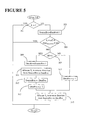
- the reverse direction is determined from the forward direction hop sequence.
- a hop of 1 is always followed by a hop of n /2- 1 , which simplifies the reverse direction sequence compared to the odd number of nodes.
- the rules for reverse direction are:
- the SourceRvs node is determined as by subtracting 1 from the DestFwd node, steps 301 and 303 . If SourceRvs ⁇ 0, then n is added to SourceRvs. This is done for every subsequent subtraction in the reverse direction allocation.
- the DestRvs node is determined by subtracting 1 from the SourceRvs node, step 309 .
- the allocation table is completed with the respective source and destination nodes, step 311 , and the DestRvs node becomes the SourceRvs for the next hop, step 313 .
- the next destination node is one node before the forward direction previous source node, (hop of 1) and thus j -2, where j is the current forward direction source node, step 315.
- the DestRvs node is one node before the forward direction source node, or j-1 , step 317 .
- Source-destination table for the wavelength allocation with n 8 Destination node Source node 1 2 3 4 5 6 7 8 1 X 0 1 2 3 (7) (5) (4) 2 (7) X 4 5 0 (6) (2) (1) 3 (5) (2) X 7 1 4 6 (0) 4 (4) (1) (0) X 2 5 7 (3) 5 3 (7) (5) (4) X 0 1 2 6 0 (6) (2) (1) (7) X 4 5 7 1 4 6 (0) (5) (2) X 7 8 2 5 7 (3) (4) (1) (0) X
- Source-destination table for the wavelength allocation with n 10 Destination Node Source node 1 2 3 4 5 6 7 8 8 10 1 X 0 1 2 3 4 (9) (6) (7) (5) 2 (9) X 5 6 7 0 (8) (11) (10) (1) 3 (6) (11) X 9 10 1 5 8 (3) (2) 4 (7) (10) (3) X 11 2 6 9 (12) (0) 5 (5) (1) (2) (0) X 3 7 10 11 12 6 4 (9) (6) (7) (5) X 0 1 2 3 7 0 (8) (11) (10) (1) (9) X 5 6 7 8 1 5 8 (3) (2) (6) (11) X 9 10 9 2 6 9 (12) (0) (7) (10) (3) X 11 10 3 7 10 11 12 (5) (1) (2) (0) X 11 10 3 7 10 11 12 (5) (1) (2) (0) X
- N 5
- This allocation leads to the source-destination table given in Table 19.
- Hop table for the wavelength allocation with n 5 nodes Added/dropped at node Wavelength 1 2 3 4 5 ⁇ 0 1 2 (3) 2 (2) ⁇ 1 (3) (1) (1) 1 4 ⁇ 2 (2) 3 (2) (1) 2 ⁇ 3 (1) 1 1 3 (4)
- Source-destination table for the wavelength allocation for n 5 nodes. Destination Node Source node 1 2 3 4 5 1 X 0 (1) (2) (3) 2 (1) X 3 0 2 3 (2) (1) X 3 (0) 4 0 3 (2) X 1 5 (3) 2 (0) 1 X
Landscapes
- Engineering & Computer Science (AREA)
- Computer Networks & Wireless Communication (AREA)
- Signal Processing (AREA)
- Optical Communication System (AREA)
- Small-Scale Networks (AREA)
- Data Exchanges In Wide-Area Networks (AREA)
Applications Claiming Priority (2)
| Application Number | Priority Date | Filing Date | Title |
|---|---|---|---|
| US323018 | 1981-11-19 | ||
| US09/323,018 US6476945B1 (en) | 1999-06-01 | 1999-06-01 | Wavelength allocation in a ring |
Publications (2)
| Publication Number | Publication Date |
|---|---|
| EP1058415A2 true EP1058415A2 (de) | 2000-12-06 |
| EP1058415A3 EP1058415A3 (de) | 2002-07-31 |
Family
ID=23257446
Family Applications (1)
| Application Number | Title | Priority Date | Filing Date |
|---|---|---|---|
| EP00304662A Withdrawn EP1058415A3 (de) | 1999-06-01 | 2000-06-01 | Wellenlängenzuweisung in einem Ring |
Country Status (4)
| Country | Link |
|---|---|
| US (1) | US6476945B1 (de) |
| EP (1) | EP1058415A3 (de) |
| JP (1) | JP2001016239A (de) |
| CA (1) | CA2308967A1 (de) |
Families Citing this family (9)
| Publication number | Priority date | Publication date | Assignee | Title |
|---|---|---|---|---|
| US20060210274A1 (en) * | 2001-02-06 | 2006-09-21 | Eyal Lichtman | Apparatus For and Method of MAC Based Transmission in WDM Optical Ring Networks |
| WO2002080428A2 (en) * | 2001-03-29 | 2002-10-10 | Atoga Systems, Inc. | Open ring architectures for optical wdm networks |
| KR100454932B1 (ko) * | 2002-07-27 | 2004-11-06 | 삼성전자주식회사 | 파장분할 다중방식을 이용한 링형 통신망의 파장할당 방법 |
| GB0416110D0 (en) * | 2004-07-19 | 2004-08-18 | British Telecomm | Path establishment |
| GB0416107D0 (en) * | 2004-07-19 | 2004-08-18 | British Telecomm | Wavelength selection |
| WO2006038248A1 (ja) * | 2004-09-30 | 2006-04-13 | Fujitsu Limited | リング伝送システムにおける光伝送装置 |
| EP2797247A1 (de) | 2013-04-24 | 2014-10-29 | British Telecommunications Public Limited Company | Optische Datenübertragung |
| WO2015052468A1 (en) | 2013-10-11 | 2015-04-16 | British Telecommunications Public Limited Company | Optical data transmission method and apparatus |
| EP3811593A1 (de) | 2018-06-21 | 2021-04-28 | British Telecommunications public limited company | Pfadauswahl für inhaltsbereitstellungsnetzwerk |
Family Cites Families (5)
| Publication number | Priority date | Publication date | Assignee | Title |
|---|---|---|---|---|
| US5774244A (en) * | 1994-01-18 | 1998-06-30 | British Telecommunications Public Limited Company | Optical communications networks |
| IT1267645B1 (it) | 1994-12-09 | 1997-02-07 | Cselt Centro Studi Lab Telecom | Struttura di comunicazione ad anello su vettore ottico e relativo nodo riconfigurabile. |
| US5751454A (en) * | 1996-10-10 | 1998-05-12 | Northern Telecom Limited | Wavelength bypassed ring networks |
| US5999288A (en) * | 1998-02-02 | 1999-12-07 | Telcordia Technologies, Inc. | Connection set-up and path assignment in wavelength division multiplexed ring networks |
| CA2242191A1 (en) * | 1998-06-30 | 1999-12-30 | Northern Telecom Limited | A large scale communications network having a fully meshed optical core transport network |
-
1999
- 1999-06-01 US US09/323,018 patent/US6476945B1/en not_active Expired - Lifetime
-
2000
- 2000-05-18 CA CA002308967A patent/CA2308967A1/en not_active Abandoned
- 2000-05-30 JP JP2000159449A patent/JP2001016239A/ja active Pending
- 2000-06-01 EP EP00304662A patent/EP1058415A3/de not_active Withdrawn
Also Published As
| Publication number | Publication date |
|---|---|
| US6476945B1 (en) | 2002-11-05 |
| CA2308967A1 (en) | 2000-12-01 |
| EP1058415A3 (de) | 2002-07-31 |
| JP2001016239A (ja) | 2001-01-19 |
Similar Documents
| Publication | Publication Date | Title |
|---|---|---|
| US5999288A (en) | Connection set-up and path assignment in wavelength division multiplexed ring networks | |
| CA2164778C (en) | Ring network communication structure on an optical carrier and reconfigurable node for said structure | |
| US5751454A (en) | Wavelength bypassed ring networks | |
| EP0762690B1 (de) | Kammverteilungsanordnung für optisches Mehrkanalnetz | |
| US7162632B2 (en) | Efficient optical network design using multi-granular optical cross-connects with wavelength band switching | |
| EP1028331A2 (de) | WDM-Multiplexer | |
| US20090047019A1 (en) | Method and System for Communicating Optical Traffic | |
| US7830789B2 (en) | Method for accommodating signal paths to ring network | |
| US20020054406A1 (en) | Bidirectional WDM optical communication network with optical bridge between bidirectional optical waveguides | |
| EP2339770A1 (de) | Optisches Ringnetzwerk mit Knoten und Verfahren | |
| EP1058415A2 (de) | Wellenlängenzuweisung in einem Ring | |
| US7085447B2 (en) | System for optically demultiplexing wavelength bands | |
| Farahmand et al. | Efficient online traffic grooming algorithms in WDM mesh networks with drop-and-continue node architecture | |
| US6885822B1 (en) | Wavelength and filter arrangement for WDM networks | |
| US6493118B1 (en) | Add/drop capability for ultra-high speed dense wavelength division multiplexed systems using a wavelength bus architecture | |
| US20030156317A1 (en) | Communications network architecture | |
| US6288812B1 (en) | Bidirectional WDM optical communication network with optical bridge between bidirectional optical waveguides | |
| Roh et al. | Design and performance evaluation of traffic grooming algorithms in WDM multi-ring networks | |
| WO2002005439A2 (en) | Bi-directional wavelength switched ring optical protection switching wavelength assignment algorithm | |
| Miyao | λ-ring system: an application in survivable WDM networks of interconnected self-healing ring systems | |
| US7389017B2 (en) | Dense wavelength division multiplexing on coarse wavelength division multiplexing networks | |
| AU2001240347B2 (en) | A communications network architecture | |
| Hsieh | Dynamic WDM network performance: The impact of banding in reconfigurable optical add/drop multiplexers | |
| Ye et al. | Optimal wavelength planning and performance analysis for full meshed WDM ring network | |
| Xu et al. | Quantifying the benefits of traffic grooming in interconnected WDM rings using a two-stage multiplexing scheme |
Legal Events
| Date | Code | Title | Description |
|---|---|---|---|
| PUAI | Public reference made under article 153(3) epc to a published international application that has entered the european phase |
Free format text: ORIGINAL CODE: 0009012 |
|
| AK | Designated contracting states |
Kind code of ref document: A2 Designated state(s): AT BE CH CY DE DK ES FI FR GB GR IE IT LI LU MC NL PT SE |
|
| AX | Request for extension of the european patent |
Free format text: AL;LT;LV;MK;RO;SI |
|
| PUAL | Search report despatched |
Free format text: ORIGINAL CODE: 0009013 |
|
| AK | Designated contracting states |
Kind code of ref document: A3 Designated state(s): AT BE CH CY DE DK ES FI FR GB GR IE IT LI LU MC NL PT SE |
|
| AX | Request for extension of the european patent |
Free format text: AL;LT;LV;MK;RO;SI |
|
| 17P | Request for examination filed |
Effective date: 20030108 |
|
| AKX | Designation fees paid |
Designated state(s): DE FR GB |
|
| 17Q | First examination report despatched |
Effective date: 20030417 |
|
| RAP1 | Party data changed (applicant data changed or rights of an application transferred) |
Owner name: NORTEL NETWORKS LIMITED |
|
| STAA | Information on the status of an ep patent application or granted ep patent |
Free format text: STATUS: THE APPLICATION IS DEEMED TO BE WITHDRAWN |
|
| 18D | Application deemed to be withdrawn |
Effective date: 20050825 |