EP1058295A2 - Magnetically coupled substrate roller - Google Patents
Magnetically coupled substrate roller Download PDFInfo
- Publication number
- EP1058295A2 EP1058295A2 EP00304678A EP00304678A EP1058295A2 EP 1058295 A2 EP1058295 A2 EP 1058295A2 EP 00304678 A EP00304678 A EP 00304678A EP 00304678 A EP00304678 A EP 00304678A EP 1058295 A2 EP1058295 A2 EP 1058295A2
- Authority
- EP
- European Patent Office
- Prior art keywords
- magnet
- shaft
- tank
- roller
- Prior art date
- Legal status (The legal status is an assumption and is not a legal conclusion. Google has not performed a legal analysis and makes no representation as to the accuracy of the status listed.)
- Withdrawn
Links
Images

Classifications
-
- H—ELECTRICITY
- H10—SEMICONDUCTOR DEVICES; ELECTRIC SOLID-STATE DEVICES NOT OTHERWISE PROVIDED FOR
- H10P—GENERIC PROCESSES OR APPARATUS FOR THE MANUFACTURE OR TREATMENT OF DEVICES COVERED BY CLASS H10
- H10P72/00—Handling or holding of wafers, substrates or devices during manufacture or treatment thereof
- H10P72/04—Apparatus for manufacture or treatment
- H10P72/0402—Apparatus for fluid treatment
- H10P72/0406—Apparatus for fluid treatment for cleaning followed by drying, rinsing, stripping, blasting or the like
- H10P72/0411—Apparatus for fluid treatment for cleaning followed by drying, rinsing, stripping, blasting or the like for wet cleaning or washing
- H10P72/0416—Apparatus for fluid treatment for cleaning followed by drying, rinsing, stripping, blasting or the like for wet cleaning or washing with the semiconductor substrates being dipped in baths or vessels
-
- Y—GENERAL TAGGING OF NEW TECHNOLOGICAL DEVELOPMENTS; GENERAL TAGGING OF CROSS-SECTIONAL TECHNOLOGIES SPANNING OVER SEVERAL SECTIONS OF THE IPC; TECHNICAL SUBJECTS COVERED BY FORMER USPC CROSS-REFERENCE ART COLLECTIONS [XRACs] AND DIGESTS
- Y10—TECHNICAL SUBJECTS COVERED BY FORMER USPC
- Y10S—TECHNICAL SUBJECTS COVERED BY FORMER USPC CROSS-REFERENCE ART COLLECTIONS [XRACs] AND DIGESTS
- Y10S134/00—Cleaning and liquid contact with solids
- Y10S134/902—Semiconductor wafer
Definitions
- the present invention relates to the rotation of thin disks. More specifically, the present invention relates to an improved roller for rotating semiconductor substrates within a tank of fluid.
- a conventional method for cleaning particles from semiconductor wafers submerged within a tank of fluid is known as megasonic cleaning.
- a transducer oscillates between compressed and strained states at a rate near 1 MHz.
- the megasonic oscillation output by the transducer is coupled to the fluid contained within the tank, causing pressure oscillation therein.
- pressure in the fluid oscillates between positive and negative, cavitations or bubbles form in the liquid during negative pressure and collapse or shrink during positive pressure. This bubble oscillation gently cleans the surface of the wafer.
- megasonic cleaners experience a number of limitations. For instance, the intensity of the cleaning energy experienced across the wafer's surface often decreases with increased distance from the transducer. This energy gradient necessitates wafer rotation in order to achieve uniform cleaning across the entire wafer surface.
- a wafer is positioned on a pair of rollers each of which are mounted to a shaft that extends through the wall of the megasonic tank. Outside the megasonic tank each shaft is coupled to a motor that when energized causes the shaft, and the roller attached thereto, to rotate. As the rollers rotate, so does the wafer positioned thereon.
- roller assemblies facilitate uniform wafer cleaning across the entire surface of the wafer, they also experience several drawbacks, such as causing cleaning fluid leakage.
- rubber seals are used to seal between the roller shaft and the wall of the tank.
- the heat and chemistry of the tank fluid degrade the seals and leaking inevitably occurs. Fluid leaking undesirably increases the system's operating costs. To reduce this cost, the leaking fluid is sometimes collected, filtered and recirculated to the tank.
- the degrading seals and leaking chemistry present a potential particle source, and, because leaking rates are random, introduce variables to the cleaning process. Eventually the seals have to be replaced causing downtime costs, as well as labor and replacement parts costs.
- the present invention overcomes the problems described above, by providing a roller which magnetically couples a driver for rotating the roller (i.e., an inventive roller/driver assembly). Because the roller and driver are magnetically coupled, no openings are required in the walls of the fluid filled processing tank, and no leakage occurs.
- an outwardly extending pocket is formed in or sealed to a wall of the processing tank, and a shaft of the inventive roller/driver assembly is supported by the pocket. This configuration has been found to provide excellent positional accuracy.
- a magnet positioned on the roller is axially offset from a magnet positioned on the driver, the driver magnet being positioned outside (i.e., in a direction away from the tank) relative to the roller magnet.
- the axial offset causes the roller magnet to be attracted outwardly, away from the tank, and thus continuously pulls the roller shaft into the pocket.
- no rings or locking devices are required to lock either the roller assembly or the driver assembly in place, and no metal parts are exposed to the cleaning fluid chemistry, therefore corrosion may be avoided.
- FIG. 1 is a front elevational view of a megasonic tank system 11.
- the megasonic tank system 11 comprises a tank 13 (e.g., a plastic tank), having a transducer 14 positioned along the bottom thereof (either inside or outside the tank 13).
- the transducer 14 may be equal in length to the diameter of a wafer W to be cleaned thereby.
- a first inventive roller assembly 15a and a second inventive roller assembly 15b are positioned to vertically support a wafer W in line with the transducer 14.
- a stabilizing mechanism 17 is positioned outside of the point along the wafer W's edge which is closest to the transducer 14, and is therefore outside of the transducer 14's highest energy field.
- the stabilizing mechanism 17 may be positioned so as to contact the wafer W at any point that will sufficiently reduce or prevent the wafer W from wobbling.
- inventive roller assemblies 15a, 15b and the stabilizing mechanism 17 each comprise a groove for supporting a wafer W with minimal contact.
- inventive roller assemblies 15a, 15b which support the wafer W are described in detail with reference to FIG. 2.
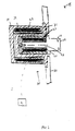
- FIG. 2 is a side elevational view of an embodiment of the inventive roller assembly 15 which may eliminate fluid leakage.
- the inventive roller assembly 15 comprises a wafer support 19 having a groove 21 in which the wafer W (FIG. 1) is positioned. To enhance friction between the wafer support 19 and the wafer W, the groove 21 may be bead blasted, knurled or may have a plurality of small holes drilled therein, along the portion of the wafer support 19 which contacts the wafer W.
- the inventive roller assembly 15 further comprises a shaft 23 having a magnet 25 coupled thereto.
- the shaft magnet 25 may be shaped like a sleeve which extends around the entire circumference of the shaft 23, although the shaft magnet 25 may be any size or shape as long as sufficient coupling exists between the shaft magnet(s) 25 and an external drive magnet 27, to achieve rotation of the shaft 23.
- the shaft magnet 25 is enclosed in a plastic enclosure 29 which is sealed to the shaft 23.
- the shaft 23 of the inventive roller assembly 15 is mounted in an outwardly extending housing or pocket 31.
- the pocket 31 may be integral with a wall 33 of the megasonic tank 13, or may be a separate housing, preferably plastic, which seals around an opening in the wall 33 of the megasonic tank 13, as shown in FIG. 2.
- the pocket 31 and the inventive roller assembly 15 are sized so that the inventive roller assembly 15 is firmly supported by the pocket 31, but is able to rotate therein.
- the pocket 31 also supports a driver assembly 35 which is external to the pocket 31.
- the driver assembly 35 comprises the drive magnet 27 which may comprise a sleeve which extends around the entire circumference of the pocket 31, although the drive magnet(s) 27 may be any size or shape as long as sufficient coupling exists between the drive magnet 27 and the shaft magnet 25.
- the shaft magnet 25 and the drive magnet 27 are of opposite polarity so that an attractive force exists therebetween. The attractive force is strong enough to rotate the roller assembly 15 when the driver assembly 35 rotates.
- the drive magnet 27 may be mounted between an outer metal housing 37 and an inner plastic housing 39, which encircles the pocket 31, and the inner plastic housing 39 may be sized so as to be firmly supported by the pocket 31 but able to rotate therearound.
- the driver assembly 35 is further coupled to a driving mechanism such as a motor 41.
- the motor 41 is energized and begins rotating the driver assembly 35.
- the magnetic coupling between the drive magnet 27 and the shaft magnet 25 causes the inventive roller assembly 15 to rotate as the driver assembly 35 rotates. Friction between the groove 21 and the wafer W positioned therein causes the wafer W to rotate.
- the transducer 14 is energized and begins oscillating at a megasonic rate. Megasonic energy is therefore coupled to the fluid and travels upward therethrough to contact the surface of the wafer W.
- the stabilizing mechanism 17 passively rotates therewith, while reducing and preferably preventing wafer wobble. Energy from the transducer 14 cleans the rotating wafer W as is known in the' art.
- the level of cleaning fluid contained within the megasonic tank 13 varies less than that experienced by megasonic tanks which employ conventional rollers. Accordingly, the inventive roller assembly 15 may add significant value to the megasonic tank 13, and to any automated cleaning/processing system in which the megasonic tank 13 is employed.
Landscapes
- Cleaning Or Drying Semiconductors (AREA)
- Rolls And Other Rotary Bodies (AREA)
- Rollers For Roller Conveyors For Transfer (AREA)
- Spinning Or Twisting Of Yarns (AREA)
Abstract
Description
Claims (11)
- A fluid containing processing tank, comprising:a tank for containing a fluid;a roller adapted to support a substrate, the roller being positioned within the tank so as to be at least partially submerged in the tank fluid;a first magnet coupled to the roller; anda second magnet positioned outside the tank and coupled to the first magnet through a wall of the tank.
- An apparatus as claimed in claim 1, wherein the roller comprises a shaft, having the first magnet coupled thereto, the tank comprises an outwardly extending pocket and the shaft is supported by the outwardly extending pocket.
- An apparatus as claimed in claim 2, wherein the first and second magnets are axially offset so as to pull the roller shaft into the pocket.
- An apparatus as claimed in any of claims 1 to 3, and further comprising a transducer coupled to the tank and a power source coupled to the transducer so that the transducer may impart sonic energy to the fluid contained in the tank.
- A roller assembly comprising:a roller having a groove adapted to support a thin disk shaped substrate;a shaft coupled to the roller such that rotation of the shaft causes rotation of the roller;a shaft magnet coupled to the shaft; andan outwardly extending pocket having an interior diameter larger than a diameter of the shaft, adapted to receive and support the shaft therein.
- An apparatus as claimed in claim 5, further comprising a driver assembly, having a drive magnet coupled to the pocket, and magnetically coupled through the pocket to the shaft magnet.
- An apparatus as claimed in claim 6, wherein the drive magnet comprises a sleeve which extends around an exterior diameter of the pocket.
- An apparatus as claimed in claim 6 or claim 7, wherein the drive magnet the shaft magnet are positioned such that when the shaft is inserted as far as possible into the pocket, the driver magnet is offset from the shaft magnet such that attraction between the drive magnet and the shaft magnet pulls inwardly on the shaft magnet.
- A method of rotating an object contained in the fluid bath, comprising:placing a roller assembly having a first magnet inside a tank containing a fluid bath;magnetically coupling the first magnet through a wall of the tank, to a second magnet; androtating the second magnet to thereby cause rotation of the roller assembly.
- A method as claimed in claim 9, wherein the step of placing the roller assembly having a first magnet inside a tank containing a fluid bath comprises supporting the roller via a pocket formed in a wall of the tank.
- A method as claimed in claim 10, further comprising offsetting the first and second magnets such that the first magnet is attracted outwardly toward the second magnet.
Applications Claiming Priority (2)
| Application Number | Priority Date | Filing Date | Title |
|---|---|---|---|
| US13690999P | 1999-06-01 | 1999-06-01 | |
| US136909P | 1999-06-01 |
Publications (2)
| Publication Number | Publication Date |
|---|---|
| EP1058295A2 true EP1058295A2 (en) | 2000-12-06 |
| EP1058295A3 EP1058295A3 (en) | 2003-11-12 |
Family
ID=22474961
Family Applications (1)
| Application Number | Title | Priority Date | Filing Date |
|---|---|---|---|
| EP00304678A Withdrawn EP1058295A3 (en) | 1999-06-01 | 2000-06-01 | Magnetically coupled substrate roller |
Country Status (4)
| Country | Link |
|---|---|
| US (1) | US6412503B1 (en) |
| EP (1) | EP1058295A3 (en) |
| JP (1) | JP4731659B2 (en) |
| TW (1) | TW531453B (en) |
Cited By (2)
| Publication number | Priority date | Publication date | Assignee | Title |
|---|---|---|---|---|
| CN105088666A (en) * | 2015-09-21 | 2015-11-25 | 核工业理化工程研究院 | Sealed transmission structure of drum-type cleaning device |
| WO2021186038A1 (en) * | 2020-03-20 | 2021-09-23 | Metalizz | Device for cleaning several pieces, by simultaneous immersion in a specific solution subjected to ultrasonic waves |
Families Citing this family (7)
| Publication number | Priority date | Publication date | Assignee | Title |
|---|---|---|---|---|
| US6918864B1 (en) * | 1999-06-01 | 2005-07-19 | Applied Materials, Inc. | Roller that avoids substrate slippage |
| WO2002095809A2 (en) * | 2001-05-18 | 2002-11-28 | Lam Research Corporation | Apparatus and method for substrate preparation implementing a surface tension reducing process |
| US6619304B2 (en) * | 2001-09-13 | 2003-09-16 | Micell Technologies, Inc. | Pressure chamber assembly including non-mechanical drive means |
| US20090159100A1 (en) * | 2007-12-24 | 2009-06-25 | Texas Instruments Incorporated | Two-piece magnetically coupled substrate roller used in megasonic cleaning process |
| US20090320875A1 (en) * | 2008-06-25 | 2009-12-31 | Applied Materials, Inc. | Dual chamber megasonic cleaner |
| US9421617B2 (en) | 2011-06-22 | 2016-08-23 | Tel Nexx, Inc. | Substrate holder |
| US8613474B2 (en) | 2011-07-06 | 2013-12-24 | Tel Nexx, Inc. | Substrate loader and unloader having a Bernoulli support |
Family Cites Families (13)
| Publication number | Priority date | Publication date | Assignee | Title |
|---|---|---|---|---|
| US3964957A (en) * | 1973-12-19 | 1976-06-22 | Monsanto Company | Apparatus for processing semiconductor wafers |
| US4052577A (en) * | 1975-09-02 | 1977-10-04 | I-T-E Imperial Corporation | Magnetically driven ring arc runner for circuit interrupter |
| US5058611A (en) * | 1989-03-27 | 1991-10-22 | Sonicor Instrument Corporation | Process and apparatus for the ultrasonic cleaning of a printing cylinder |
| US5090432A (en) * | 1990-10-16 | 1992-02-25 | Verteq, Inc. | Single wafer megasonic semiconductor wafer processing system |
| JPH06182281A (en) * | 1992-12-21 | 1994-07-05 | Kawasaki Steel Corp | Driver for immersion roll |
| JPH07227583A (en) * | 1994-02-17 | 1995-08-29 | Ebara Corp | Immersion stirring type cleaning device |
| JPH07313946A (en) * | 1994-05-26 | 1995-12-05 | Hitachi Ltd | Magnetic disk substrate cleaning device |
| US5672212A (en) * | 1994-07-01 | 1997-09-30 | Texas Instruments Incorporated | Rotational megasonic cleaner/etcher for wafers |
| JPH10223585A (en) * | 1997-02-04 | 1998-08-21 | Canon Inc | Wafer processing apparatus and method, and method for manufacturing SOI wafer |
| JP3672416B2 (en) * | 1997-06-27 | 2005-07-20 | 株式会社荏原製作所 | Spin processing equipment |
| DE59712899D1 (en) * | 1997-08-25 | 2008-01-10 | Lust Antriebstechnik Gmbh | Magnetic bearing rotation arrangement |
| US6247889B1 (en) * | 1998-07-31 | 2001-06-19 | Bks Lab. Ltd. | Multiple-shaft power transmission apparatus and wafer transport arm link |
| US6119708A (en) * | 1998-11-11 | 2000-09-19 | Applied Materials, Inc. | Method and apparatus for cleaning the edge of a thin disc |
-
2000
- 2000-05-30 US US09/583,145 patent/US6412503B1/en not_active Expired - Fee Related
- 2000-06-01 JP JP2000164942A patent/JP4731659B2/en not_active Expired - Fee Related
- 2000-06-01 EP EP00304678A patent/EP1058295A3/en not_active Withdrawn
- 2000-08-01 TW TW089110636A patent/TW531453B/en not_active IP Right Cessation
Cited By (3)
| Publication number | Priority date | Publication date | Assignee | Title |
|---|---|---|---|---|
| CN105088666A (en) * | 2015-09-21 | 2015-11-25 | 核工业理化工程研究院 | Sealed transmission structure of drum-type cleaning device |
| WO2021186038A1 (en) * | 2020-03-20 | 2021-09-23 | Metalizz | Device for cleaning several pieces, by simultaneous immersion in a specific solution subjected to ultrasonic waves |
| FR3108265A1 (en) * | 2020-03-20 | 2021-09-24 | Metalizz | Device for cleaning several parts, by simultaneous immersion in a specific solution subjected to ultrasonic waves |
Also Published As
| Publication number | Publication date |
|---|---|
| TW531453B (en) | 2003-05-11 |
| EP1058295A3 (en) | 2003-11-12 |
| JP4731659B2 (en) | 2011-07-27 |
| US6412503B1 (en) | 2002-07-02 |
| JP2001110770A (en) | 2001-04-20 |
Similar Documents
| Publication | Publication Date | Title |
|---|---|---|
| US6412503B1 (en) | Magnetically coupled substrate roller | |
| KR100420488B1 (en) | Fluid processing method of an object to be processed and apparatus thereof | |
| US5672212A (en) | Rotational megasonic cleaner/etcher for wafers | |
| US6918864B1 (en) | Roller that avoids substrate slippage | |
| US5927305A (en) | Cleaning apparatus | |
| US9296022B1 (en) | Sonication cleaning system | |
| EP0839586B1 (en) | A cleaning apparatus and a cleaning method | |
| JP2007005710A (en) | Substrate cleaning processing equipment | |
| KR100625307B1 (en) | Semiconductor Substrate Cleaning Device | |
| JPH10244201A (en) | Substrate processing equipment | |
| KR101120617B1 (en) | Apparatus method for wet treatment of wafers | |
| US6497241B1 (en) | Hollow core spindle and spin, rinse, and dry module including the same | |
| JP2005307281A (en) | Barrel plating method and device | |
| CN210115750U (en) | Automatic fluid sweeps ray apparatus | |
| KR20220043675A (en) | cleaning device FOR DIFFUSER | |
| JP4421740B2 (en) | Roller to avoid board slip | |
| JP2003282515A (en) | Substrate processing equipment | |
| KR100711291B1 (en) | Substrate Transfer Shaft Support Device | |
| KR100767038B1 (en) | Substrate Transfer Device | |
| JPH11111822A (en) | Wafer chuck device | |
| JP2012161712A (en) | Wet cleaning device, wet cleaning method, and method for producing substrate for magnetic recording medium | |
| JP3664856B2 (en) | Rotary substrate processing equipment | |
| US6490304B1 (en) | Excimer laser device | |
| JP2007027784A (en) | Versatile cleaner | |
| JP2000223470A (en) | Wet etching equipment |
Legal Events
| Date | Code | Title | Description |
|---|---|---|---|
| PUAI | Public reference made under article 153(3) epc to a published international application that has entered the european phase |
Free format text: ORIGINAL CODE: 0009012 |
|
| AK | Designated contracting states |
Kind code of ref document: A2 Designated state(s): AT BE CH CY DE DK ES FI FR GB GR IE IT LI LU MC NL PT SE |
|
| AX | Request for extension of the european patent |
Free format text: AL;LT;LV;MK;RO;SI |
|
| RIC1 | Information provided on ipc code assigned before grant |
Ipc: 7H 01L 21/306 B Ipc: 7H 01L 21/00 A |
|
| PUAL | Search report despatched |
Free format text: ORIGINAL CODE: 0009013 |
|
| AK | Designated contracting states |
Kind code of ref document: A3 Designated state(s): AT BE CH CY DE DK ES FI FR GB GR IE IT LI LU MC NL PT SE |
|
| AX | Request for extension of the european patent |
Extension state: AL LT LV MK RO SI |
|
| AKX | Designation fees paid | ||
| REG | Reference to a national code |
Ref country code: DE Ref legal event code: 8566 |
|
| STAA | Information on the status of an ep patent application or granted ep patent |
Free format text: STATUS: THE APPLICATION IS DEEMED TO BE WITHDRAWN |
|
| 18D | Application deemed to be withdrawn |
Effective date: 20040513 |