EP1058266A2 - Library apparatus of storage media - Google Patents
Library apparatus of storage media Download PDFInfo
- Publication number
- EP1058266A2 EP1058266A2 EP00250156A EP00250156A EP1058266A2 EP 1058266 A2 EP1058266 A2 EP 1058266A2 EP 00250156 A EP00250156 A EP 00250156A EP 00250156 A EP00250156 A EP 00250156A EP 1058266 A2 EP1058266 A2 EP 1058266A2
- Authority
- EP
- European Patent Office
- Prior art keywords
- magazine
- cartridge
- loading
- library apparatus
- unloading
- Prior art date
- Legal status (The legal status is an assumption and is not a legal conclusion. Google has not performed a legal analysis and makes no representation as to the accuracy of the status listed.)
- Granted
Links
Images














Classifications
-
- G—PHYSICS
- G11—INFORMATION STORAGE
- G11B—INFORMATION STORAGE BASED ON RELATIVE MOVEMENT BETWEEN RECORD CARRIER AND TRANSDUCER
- G11B15/00—Driving, starting or stopping record carriers of filamentary or web form; Driving both such record carriers and heads; Guiding such record carriers or containers therefor; Control thereof; Control of operating function
- G11B15/675—Guiding containers, e.g. loading, ejecting cassettes
- G11B15/68—Automatic cassette changing arrangements; automatic tape changing arrangements
- G11B15/682—Automatic cassette changing arrangements; automatic tape changing arrangements with fixed magazines having fixed cassette storage cells, e.g. in racks
- G11B15/683—Automatic cassette changing arrangements; automatic tape changing arrangements with fixed magazines having fixed cassette storage cells, e.g. in racks wherein the recorder or player is moved according to the location of a selected cassette
-
- G—PHYSICS
- G11—INFORMATION STORAGE
- G11B—INFORMATION STORAGE BASED ON RELATIVE MOVEMENT BETWEEN RECORD CARRIER AND TRANSDUCER
- G11B17/00—Guiding record carriers not specifically of filamentary or web form, or of supports therefor
- G11B17/22—Guiding record carriers not specifically of filamentary or web form, or of supports therefor from random access magazine of disc records
- G11B17/225—Guiding record carriers not specifically of filamentary or web form, or of supports therefor from random access magazine of disc records wherein the disks are transferred from a fixed magazine to a fixed playing unit using a moving carriage
Definitions
- the present invention relates generally to a library apparatus of storage media, in which a magazine housing a plurality of cartridges, each receiving a storage medium, is loaded, and a desired one of the storage media received within the magazine is accessed for reading information from the storage medium, writing information in the storage medium, and performing both of reading and writing information. More particularly, the invention relates to an improvement in a loading mechanism for loading and ejecting the magazine.
- the loading mechanisms for loading and unloading the magazines as disclosed in the above-identified publications are designed for performing loading and unloading utilizing a driving force of a motor in view of that a conventionally employed structure for manually loading and unloading the magazine utilizing a biasing means, such as a spring or the like, can cause instability in loading and unloading operation of the magazine.
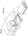
- a magazine 2 to be provided for a library apparatus 1 houses three cartridges 3, each of which receives therein a storage medium.
- a rack 2a is provided on a lower portion of external side surface of a casing of the magazine 2.
- the cartridge transporting mechanism which can be lifted up and down, is arranged on the front side portion of the library apparatus 1.
- a medium driving device 5 for performing reading from and writing in the storage medium housed in the cartridge is arranged in the upper side of the medium driving device 5, a holder device 6 for receiving the loaded magazine 2, is arranged.
- the magazine 2 is inserted into the holder device 6 through an opening formed in the front side.
- a magazine feeding motor 7 is provided on the side of the opening.
- a pinion 8 for meshing with the rack 2a of the magazine is secured.
- the lid body 1a Upon loading the magazine in the library apparatus, by pushing the lid body 1a with the magazine 2, the lid body 1a is opened in response to pushing force exerted through the magazine 2 for permitting insertion of the magazine 2.
- the cartridge transporting mechanism 3 is located at a lowered position.
- the magazine 2 is moved as guided by an upper surface of the cartridge transporting mechanism 3.
- the magazine feeding motor 7 By a detection signal of the sensor, the magazine feeding motor 7 is actuated to drive the pinion for rotation.
- the rack 2a By rotation of the pinion, the rack 2a is driven to move for drawing the magazine 2 into the holder device 6.
- the magazine feeding motor 7 is stopped to place the magazine in a condition loaded in the library device.
- the storage media housed in the cartridges received within the magazine can be loaded on the medium driving device 5.
- the cartridge transporting mechanism 4 Upon loading the storage medium on the medium driving device 5, the cartridge transporting mechanism 4 is elevated up to the position opposing to the desired cartridge 3. Then, by means of a not shown gripping means provided in the cartridge transporting mechanism 4, the cartridge 3 is gripped and is withdrawn from the magazine 2 by inserting and withdrawing a mechanism which is designed to move the gripping means in horizontal direction, Then, the cartridge 3 is held on the cartridge transporting mechanism 4. Thereafter, the cartridge transporting mechanism 4 is lowered to oppose to the medium driving device 5. Then, the held cartridge is pushed out to be inserted into the medium driving device 5.
- the cartridge 3 is withdrawn from the medium driving device 5 by the cartridge transporting mechanism 4 to return into the magazine 2, and then, another cartridge 3 is withdrawn from the magazine and inserted into the medium driving device 5.
- a lifting motor for driving the cartridge transporting mechanism 4 for lifting up and down, an inserting and withdrawing motor for driving the gripping means in horizontal direction for moving the cartridge 3 and so forth are incorporated in addition to the magazine feeding motor 7.
- a lifting motor for driving the cartridge transporting mechanism 4 for lifting up and down, an inserting and withdrawing motor for driving the gripping means in horizontal direction for moving the cartridge 3 and so forth are incorporated in addition to the magazine feeding motor 7.
- at least three motors are employed, a large number of parts are required and construction becomes complicate. Also, since at least three motors are provided, installation spaces therefore are required to increase the size of the library apparatus.
- the pinion 8 since the pinion 8 has to be arranged at the position out of the range of up and down motion of the cartridge transporting mechanism 4, the pinion 9 is arranged in the vicinity of the holder device 6.
- the magazine 2 when the magazine 2 is ejected from the library apparatus 1, the magazine 2 has to be projected from the lid body 1a of the library apparatus 1 in the extent of permitting gripping by human fingers. Furthermore, at this projected position, the tip end of the rack 2a has to be kept in meshing engagement with the pinion 8. Therefore, the length of the magazine in the loading direction has to correspond to the sum of the length of the cartridge transporting mechanism 4 and the length of projection from the library apparatus 1. Therefore, the magazine 2 is required to have approximately double the length of the cartridge 3 to make the magazine bulky.
- a library apparatus of a storage media for reading and/or writing information from and in to a storage medium housed in a cartridge by withdrawing a desired one of a plurality of cartridges housed within a magazine which is loaded in an apparatus body, by cartridge loading and unloading means and loading the withdrawn cartridge in medium drive means comprises:
- the cartridge loading and unloading means performing loading and unloading the cartridge from the magazine, loading and unloading of the magazine is also performed. Therefore, no dedicated motor for loading the magazine is necessary to be provided. Therefore, the number of parts can be reduced and construction can be simplified.
- a magazine holder for receiving the magazine is provided within the apparatus body, and the cartridge loading and unloading means transports the magazine inserted through a magazine insertion opening of the apparatus body to the magazine holder, and then grips and withdraws a desired one of cartridges from the loaded magazine.
- the cartridge loading and unloading means may transport the magazine inserted through the magazine insertion opening by repeating operation for a plurality of times.
- the size of the magazine is greater than the size of the cartridges.
- the stroke of loading and unloading operation by the cartridge loading and unloading means is required to be sufficiently large for loading and unloading the cartridge, which is not sufficient for loading and unloading the magazine in and from the library apparatus.
- the magazine inserted through the magazine insertion opening of the apparatus body can be transported to the magazine holder by repeating operation for a plurality of times.
- the cartridge loading and unloading means may be mounted on cartridge moving means which is moved up and down with mounting the cartridge loading and unloading means.
- the cartridge loading and unloading means may be provided with latching portion and the magazine is provided with a latch receiving portion for releasably engaging with the latching portion, and the latching portion and the latch receiving portion may be engaged and released by up and down motion of the cartridge loading and unloading means by the cartridge moving means.
- One cartridge withdrawn from the magazine by the cartridge loading and unloading means is moved to the media drive means by the cartridge moving means as supported by the cartridge loading and unloading means. Also, when one cartridge is moved to the medium drive means by the cartridge moving means after withdrawing one cartridge from the magazine by the cartridge loading and unloading means, the magazine is separated from the cartridge loading and unloading means.
- the library apparatus may further comprise magazine positioning means for positioning the magazine inserted through the magazine insertion opening at a predetermined position located away from the magazine holder, and the cartridge loading and unloading means may transport the magazine from the predetermined position to the magazine holder.
- the magazine positioning means may be provided on a lid body closing the magazine insertion opening and may be responsive to pushing of the magazine through the magazine insertion opening to be placed at open position, the magazine positioning means may engage with the magazine in the condition where the lid body is opened, to position the magazine at the predetermined position, the magazine positioning means may release engagement with the magazine as shifted by driving means, the cartridge loading and unloading means may transport the magazine into the magazine holder after releasing the magazine positioning means from the magazine.
- Fig. 1 is a schematic perspective view showing a library apparatus 20 and a magazine 10 to be loaded in the library apparatus.
- a housing of the library apparatus 20 is illustrated in see-through manner for explanatorily showing the internal construction.
- a desired number of cartridges 11 are releasably received.
- three cartridges 11 are received in the magazine 10.
- a storage medium for reading and writing information or both is received.
- a latch receiving portion 12 serving as latching receiving means formed by a recessed portion, through opening or the like of an arbitrary shape, is provided.
- the four latch receiving portions are formed in the top plate at four positions.
- the latch receiving portion formed on the rear side of the library apparatus is identified by the reference numeral 12a, and the latch receiving portion formed on the front side of the library apparatus is identified by the reference numeral 12b.
- the library apparatus 20 is constructed with a housing 21 formed in substantially rectangular parallelpiped shape, a cartridge transporting device 30, a medium driving device 50 as medium driving means for performing reading and writing information for the storage medium received in the cartridge 11, a magazine holder 60 holding the magazine within the housing 21, and control portion 70 for controlling operation of the library apparatus 20,
- the cartridge transporting device 30, the medium driving device 50, the magazine holder 60 and the control portion 70 are housed within the housing 21.
- a lid body 22 is swingable about a lower edge. The lid body 22 is installed on the front mask 23.
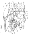
- Fig. 2 is a perspective view showing a general construction of the cartridge transporting device 30.
- the cartridge transporting device 30 is arranged at the front portion of the housing 21.
- the cartridge transporting device 30 is constructed by mounting a hand device 40 which is movable in a direction for loading and unloading the cartridge 11 into and from the medium driving device 50 and thus serve as the cartridge loading and unloading means, and a picker device 32 as cartridge moving means, on which the cartridge transporting device 30 is mounted.
- the picker device 32 is disposed between a bottom base 30a as lower base plate and a top base 30b as an upper base plate.
- vertically extending guide rods 33 are supported at both end portions.
- the other edge portions of the bottom base 30a and the top base 30b are connected by a wall plate 30c.
- a frame is formed by the bottom base 30a, the top base 30b, the guide rod 33 and the wall plate 30c.
- the picker device 32 is arranged within the frame.
- a screw shaft 34 Adjacent the guide rod 33, a screw shaft 34 is arranged. Both ends of the screw shaft 34 are rotatably supported on the bottom base 30a and the top base 30b. A shaft driving motor 35 is supported in the vicinity of the screw shaft 34. Rotation of an output shaft of the shaft driving motor 35 is transmitted to the screw shaft 34 via a power transmission mechanism, such as a not shown gear train.
- a slider 36 is provided at one end portion of a picker base 32a of the picker device 32.
- the guide rod 33 is inserted through a through hole formed in the slider 36. Therefore, the picker device 32 is lifted up and down as guided by the guide rod 33.
- guide means such as a vertically extending guide hole formed as an elongated hole in the wall plate 30c, and providing guide projection loosely inserting into the guide hole on the picker base 32a, for smoothly lifting up and down the picker device 32.
- a guide pin 36a is extended from the slider 36. A tip end portion of the guide pin 36a is loosely inserted into a screw groove 34a of a screw portion of the screw shaft 34.
- the hand device 40 is provided on the picker base 32a of the picker device 32.
- Fig. 3 is a perspective view showing a general construction of the hand device 40 as viewed from the front side.
- the hand device 40 has a hand plate 41.
- a pair of hands 42 are supported for pivoting about vertical axes. By pivoting motion, the hands 42 are opened and closed for gripping the side surfaces of the cartridge 11 at the closed position.
- a hand spring 42a is stretched. By a restoring force of the hand spring 42a, the hands 42 are biased in closing direction.
- a pair of pushers 43 are slidably supported in moving direction of the hand plate 41.
- the pushers 43 are biased by restoring force of the pusher springs 43a to extend toward the hands 42.
- the opening and closing mechanism of the hands 42 may be similar to the known mechanism.
- bracket portions 41b and 41c are formed projecting frontwardly.
- guide rollers 44 are rotatably supported.
- both ends of the front side of the hand plate 41 are bent at the front end portion into a substantially channel shaped configuration after projecting frontwardly, and are bent downwardly at a rear end portion for forming hooking craw portions 45 as latching means.
- the hooking claw portion 45 is formed into a shape releasably engaging with latch receiving portion 12 formed in the magazine 10. It should be noted that the hand device 40 may be similar to the conventionally known mechanism and in the alternative, a construction, in which the hooking claw portion 45 is provided for the known mechanism.
- Fig. 4 is a perspective view showing a general construction of the picker device as viewed from the front side.
- a gear base plate 32b is mounted in the lower portion of the picker base 32a.
- a pair of guide rails 81 are mounted with orienting its longitudinal axis along a moving direction of the hand plate 41.
- a pair of driving pulleys 82a and 82b are rotatably supported between the pair of guide rails 81.
- a drive belt 83 is stretched.
- a hand driving motor 84 is mounted so that rotation of an output shaft thereof is transmitted to the driving pulley 82a with appropriately changing speed by an appropriate gear train 85.
- the hand plate 41 is secured to the driving belt 83.
- the guide rollers 44 are engaged with the guide rail 81. Accordingly, when the driving belt 83 is driven by the driving pulleys 82a and 82b, the guide rollers 44 are guided along the guide rails 81 for moving the hand plate 41 in horizontal direction.
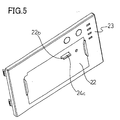
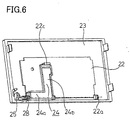
- Figs. 5 and 6 are illustrations of the lid body 22.
- Fig. 5 is a perspective view of the lid body as viewed from outside of the housing 21 and
- Fig. 6 is a perspective view of the lid body as viewed from inside of the housing.
- At lower center portion of the front mask 23 is formed an opening to define a magazine insertion opening.
- the lid body 22 is provided for closing the magazine insertion opening.
- the lid body 22 is supported by a shaft 22a extending along the lower side edge of the front mask 23 for pivotal motion thereabout.
- the lid body 22 is formed with an engaging hole 22b which is a substantially rectangular through opening.
- a hook portion 22c is formed for covering the engaging hole 22b with a given distance from a back surface of the lid body 22 by projecting rearwardly and downwardly bending the tip end.
- a substantially L-shaped lid body engaging plate 24 is arranged on the back surface of the lid body 22 on the back surface of the lid body 22.
- a support arm 24a forming a part of the L-shaped lid body engaging plate 24, extends along the lower edge portion of the lid body 22 to reach the side portion of the lid body 22.
- an action arm 24b forming the other portion of the L-shaped lid body engaging plate 24 extends to the position opposing to the engaging hole 22b.
- the tip end portion of the action arm 24b is bent frontwardly to form an engaging projection 24c.
- the engaging projection 24c extends through the engaging hole 22b to project to the front surface side of the lid body 22 for a predetermined length.
- the support arm 24a of the lid body engaging plate 24 is supported coaxially with the shaft 22a of the lid body 22 so that the lid body engaging plate 24 may pivot about the shaft 22a.
- an engaging hook portion 25 is formed in the tip end portion of the support arm 24a, as shown in Fig. 10.
- the engaging hook portion 25 is formed into arc-shaped configuration with a curvature centered at about an axis parallel to the shaft 22.
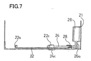
- a solenoid 26 which serves as positioning means driving means is provided as fixed on the bottom plate of the housing 21.
- An actuation rod 26a of the solenoid extends frontwardly.
- An engaging portion 27 formed at the tip end of the actuation rod 26a is engaged with the arc-shaped engaging hook portion 25 at the inside of the arc. Therefore, when the solenoid 26 is actuated to retract the actuation rod 26a, the engaging hook portion 25 is pivoted.
- the lid body engaging plate 24 having the engaging hook 25 is pivoted about the shaft 22 so that the engaging projection 24c is retracted within the engaging hole 22b.
- the lid body engaging plate 24 is biased by the restoring force of a return spring 28 which is formed with a torsion coil spring, toward the back surface of the lid body 22.
- a drive control portion 72 is included for driving the shaft driving motor 35, the hand driving motor 84 and the solenoid 26.
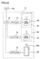
- Fig. 33 is a block diagram showing a general construction of the drive control portion 71.
- the drive control portion 71 includes CPU 72 executing a predetermined sequence according to a command from a host computer 70a as a superior unit, motor drivers 73 and 74 for outputting drive signals according to a command from CPU 72, and a solenoid driver 75.
- the shaft driving motor 35 for lifting the picker device 32 up and down is driven for revolution in the direction commanded by an output signal of the motor driver 74.
- the hand driving motor 84 for shifting the hand plate 41 is driven for revolution in the direction commanded by an output signal of the motor driver 73.
- the solenoid 26 is turned ON and OFF by the output signal of the solenoid driver 75 for shifting the actuation rod 26a in the given direction.
- Fig. 34 is a flowchart showing the case where the magazine 10 is loaded in the library apparatus 10.
- the picker device 32 For waiting insertion of the magazine 10 through the magazine insertion opening, the picker device 32 is elevated at the uppermost position and thus is located at a transportation home position (hereinafter referred to as "transporting HP") as an origin, and the hand device 40 is shifted to the most frontwardly shifted position at an origin which position is referred to as loading and unloading home position (hereinafter referred to as “loading and unloading HP”), respectively (step 3400).
- transporting HP transportation home position
- loading and unloading HP loading and unloading home position
- Fig. 11 is a schematic sectional view showing the library apparatus in the condition before insertion of the magazine, with cutting out the side surface thereof.
- the lid body engaging plate 24 is biased by the restoring force of the return spring 28 to abut against the lid body 22 to place the latter in a condition closing the magazine insertion opening.
- the engaging projection 24c formed at the tip end portion of the action arm 24b of the lid body engaging plate 24 is projected front side of the lid body through the engaging hole 22b formed through the lid body 22.
- the actuation rod 26a of the solenoid 26 is maintained in projected position.
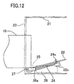
- Fig. 12 is a section of the side surface of the library apparatus showing the initial condition where the magazine 10 is just inserted.
- the magazine 10 is slightly inserted.
- the lid body 20 is depressed to pivot toward inside of the housing 21 about the shaft 22a.
- the lid body 22 is further pivoted to be positioned in substantially horizontally oriented position with directly the front surface upwardly.
- the magazine 10 moves with sliding on the front surface of the lid body 22 to contact with the engaging projection 24c as shown in Fig. 18.
- the latch receiving portion 12a formed in the magazine 10 is positioned below the hooking claw portion 45 of the hand device 40 in the loading and unloading HP.
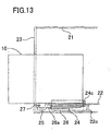
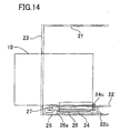
- the magazine 10 When the magazine 10 at the position where the front end is abutted onto the engaging projection 24c, is detected by a not shown position sensor for example, the magazine 10 is situated in the condition where insertion thereof is completed (step 3402/YES). Then, a signal indicative of insertion completion is output to the control portion 70. Then, the host computer 70a transmits the command for drawing the magazine 10 to CPU 72. CPU 72 transmits a drive signal for the solenoid driver 75. Then, the solenoid driver 75 actuates the solenoid 26 (step 3403). By this, the actuation rod 26a is retracted to cause pivotal movement of the engaging hook portion 25 about the shaft 22 which engages with the tip end of the actuation rod 26a, in clockwise direction in Fig. 13. Since the engaging hook portion 25 is formed on the lid body engaging plate 24, the lid body engaging plate 24 is pivoted in the same direction to cause releasing of engagement with the magazine 10 by withdrawing the engaging projection 24c from the engaging hole 22b.
- CPU 72 transmits a drive signal to the motor driver to drive the shaft driving motor 35 (step 3403).
- the screw shaft 34 connected thereto is driven to rotate.
- the guide pin 36a is connected to the screw shaft 34, the guide pin 36a is driven vertically along the screw groove 34a.
- the picker device 32, on which the guide pin 36a is provided is elevated.
- the vertical direction of motion of the picker device 32 is variable depending upon the rotating direction of the screw shaft 34.
- the picker device 32 located at the transportation HP is lowered. Namely, the shaft driving motor 35 is driven for revolution in the direction for lowering the picker device 32. This direction of revolution of the shaft driving motor 35 is hereinafter referred to as forward direction.
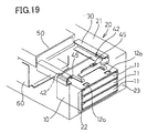
- the hooking claw portion 45 provided in the band plate 41 is inserted into the latch receiving portion 12a formed in the top plate of the magazine, as shown in Fig. 19.
- the position where the magazine is positioned by abutting onto the engaging projection 24c corresponds to the position where the engaging claw portion 45 and latch receiving portion 12a are engaged. Then, at the condition where the engaging claw portion 45 and the latch receiving portion 12a are engaged, the shaft driving motor 35 is stopped.
- CPU 72 feeds a drive signal to the hand drive motor 84 for actuation (step 3404).
- the hand driving motor 84 is actuated to transmit rotational output thereto to the driving pulley 83a through the gear train 85, the driving belt 83 stretched between the driving pulley 83a and the driving pulley 83b is driven to circulate. Since the hand plate 41 is engaged with the drive belt 83, the hand plate 41 is also shifted according to circulation of the drive belt 83. Shifting direction of the hand plate 41 is variable depending upon the direction of revolution of the hand driving motor 84. Upon loading the magazine 10, the hand plate 41 is retracted inside of the library apparatus 20.
- the driving direction of the hand driving motor 84 in this case is hereinafter referred to as forward direction.
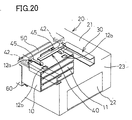
- the magazine, the latching receiving portion thereof being in engagement with the hooking claw portion 45 is then drawn toward the magazine holder 60. This condition is shown in Fig. 20.
- the magazine 10 can be received within the magazine holder 60 at one time of retracting action of the hand plate 41, loading of the magazine 10 can be completed.
- the shifting operation of the hand plate 41 is for transferring the cartridge 11 in the loaded magazine 10 to the media drive device 50, one only requires a stroke sufficient for withdrawing the cartridge 11 front the magazine 10 and inserting the cartridge into the medium drive device 50.
- the magazine 10 is designed to receive the cartridges therein and is greater than the cartridge in certain extent, and also, a part of the magazine 10 is required to project from the magazine insertion opening of the library device upon loading and unloading the magazine 10.
- the shifting distance of the magazine upon loading the magazine 10 within the magazine holder 60 should be greater than the stroke required for withdrawing and inserting the cartridge from and into the magazine. Accordingly, retracting operation of the hand plate at one time should be insufficient for completing loading operation of the magazine 10.
- the hand driving motor 84 is stopped. Then, the shaft drive motor 35 is driven in reverse direction to elevate the picker device 32 to the transportation HP (step 3405). By upward movement of the picker device 32, the hooking claw portion 45 is released from the latch receiving portion 12a of the magazine. Then, the hand driving motor 84 is driven in reverse direction to extract the band plate 41 to the loading and unloading HP (step 3406). Subsequently, the shaft driving portion 35 is driven in forward direction to lower the picker device 32. Then, as shown in Fig. 21, the hooking claw portion 45 is located at front side beyond the front face of the magazine 10 (step 3407).
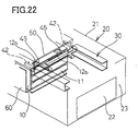
- the shaft driving motor 35 As lowered down to the predetermined position, the shaft driving motor 35 is stopped. Then, the hand driving motor 8s is driven in forward direction. By driving the hand driving motor 84 in forward direction, the hand plate 41 is again retracted to abut the hooking claw portion 45 with the front face of the magazine to push the magazine 10. Therefore, the magazine 10 is fed to the inner side of the library apparatus to be received in the magazine holder 60 as shown in Fig. 22 (step 3408).
- the solenoid 26 is stopped (step 3411).
- the actuation rod 26a becomes free to constraint by the engaging hook portion 25 to make the lid body engaging plate 24 free. Therefore, the lid body engaging plate 24 is biased toward the lid body 22 by the restoring force of the return spring 28 to pivot the lid body into the closed position.
- the picker device 32 is moved to the transportation HP and the hand device 40 is moved to the loading and unloading HP to wait for command from the host computer 70a.
- the picker device 32 is lowered to the position where the cartridge 11 in the magazine 10 loaded in the magazine holder 50 can be withdrawn.
- the hand plate 41 is driven to retract so that the hand may grip the cartridge 11.
- the hand plate 41 is driven to retract so that the hand may grip the cartridge 11.
- the cartridge 11 is withdrawn from the magazine 10 to transfer to the picker device 32.
- the picker device 32 is lowered to place the cartridge 11 held by the picker device 32 at a position to be inserted into the media drive device 50.
- the hand plate 41 is retracted to load the cartridge in the media drive device 50.
- the cartridge 11 is placed in position loaded in the medium drive device 50.
- the medium drive device 50 can read and write information for the storage medium received in the cartridge 11.
- the hand plate 41 In order to exchange the cartridge 11, the hand plate 41 is retracted to grip the cartridge loaded in the medium drive device 50. Then, the hand plate 41 is driven frontwardly to withdraw the cartridge 11 from the medium drive device 50 to return to the space within the magazine. Thereafter, the next cartridge 11 to be loaded in the medium drive device 50 is withdrawn from the magazine 10 for transport to the medium drive device 50. It should be noted that for gripping operation of the cartridge 11 by the hand 42, known loading and unloading mechanism can be employed.
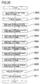
- Fig. 35 is a flowchart showing the case where the magazine 10 is ejected from the library apparatus 20.
- drive signals are fed from CPU 72 to the motor drivers 73 and 74 to actuate the shaft driving motor 35 and the hand driving motor 84.
- the picker device 32 is placed at the transportation HP and the hand device 40 is loading and unloading HP (step 3500).
- the solenoid 26 is actuated to retract the actuation rod 26a to open the lid body 22 (step 3501).
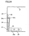
- Fig. 23 shows a condition where the lid body 22 is closed. At this condition, when the actuation rod 26a of the solenoids 26 is retracted to cause pivotal motion of the engaging hook portion 25. Then, the lid body engaging plate 24 is pivoted in clockwise direction in fig. 23. By this pivotal motion, as shown in Fig. 24, the back surface of the action arm 24b of the lid body engaging plate 24 contacts with the hook portion 22c formed on the back surface of the lid body 22. Therefore, as shown in Fig. 25, the lid body is pivoted in the same direction as pivoting direction of the lid body engaging plate 24 to open the lid body 22. Then, when the lid body 22 is pivoted to the position as being oriented in substantially horizontal direction as shown in Fig. 26, it becomes possible to eject the magazine. It should be noted that the engaging projection 24c of the lid body engaging plate 24 is drawn below the lid body 22 so as not to interfere with the ejection of the magazine 10.
- the hand driving motor 84 is driven in forward direction.
- the hand device 40 is retracted up to the rearmost position (step 3502).
- the hooking claw portion 45 is also retracted to be placed above the latch receiving portion 12b of the magazine 10.
- the shaft driving motor 35 is driven in forward direction, the picker device 32 is lowered (step 3503).
- the hooking claw portion 45 is inserted into the latch receiving portion 12b to engage therewith.
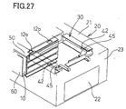
- the magazine 10 can be withdrawn from the magazine holder 60 as shown in Fig. 30. Furthermore, the magazine 10 can only be withdrawn at halfway in the first forward operation of the hand device 40. Therefore, a second withdrawing operation is performed. Namely, by driving the shaft driving motor 35 and the hand driving motor 84 in reverse direction, respectively, the picker device 32 is placed at the transportation HP and the hand device 40 is placed in the loading and unloading HP (step 3505).
- the hand driving motor 84 is driven in forward direction, the hand device 40 is retracted to the rearmost position (step 3506). Also, the shaft driving motor 35 is driven in forward direction, the picker device 32 is lowered (step 3507). By lowering of the picker device 32, the hooking claw portion 45 can engage with the back surface of the magazine 10. By driving the hand driving motor 84 in forward direction, the hand device 40 is driven frontwardly to the loading and unloading HP (step 3508). Then, the back surface of the magazine 10 is pushed by the hooking claw portion 45 to project over the front portion of the magazine 10 from the insertion hole of the library apparatus 20 to complete ejecting operation of the magazine 10 (step 3510).
- the lid body 22 is permitted to be placed at the closed position for closing the insertion opening by the restoring force of the return spring 28.
- the lid body 22 is placed in the closed position.
- the cartridge loading and unloading means for withdrawing desired one cartridge from the magazine can perform loading and unloading of the magazine to the apparatus body. Accordingly, the number of motors to be provided in the library apparatus can be reduced. Thus, the number of parts can be reduced according to reduction of the number of motors. Thus, construction can be simplified.
- the cartridge loading and unloading means transports the magazine inserted through a magazine insertion opening of the apparatus body to the magazine holder, and then grips and withdraws a desired one of cartridges from the loaded magazine. Therefore, loading operation of the magazine and withdrawing of the cartridge can be performed sequentially.
- the cartridge loading and unloading means transports the magazine inserted through the magazine insertion opening by repeating operation for a plurality of times. Therefore, even when the stroke for inserting and withdrawing the cartridge to and from the magazine is too short for loading and unloading operation of the magazine, the magazine can be certainly loaded and unloaded.
- the cartridge loading and unloading means is mounted on cartridge moving means which is moved up and down with mounting the cartridge loading and unloading means.
- the cartridge withdrawn from the magazine by the cartridge loading and unloading means can be stably loaded in the medium drive means.
- the cartridge loading and unloading means is provided with a latching portion and the magazine is provided with a latch receiving portion for releasably engaging with the latching portion, the latching portion and the latch receiving portion are engaged and released by up and down motion of the cartridge loading and unloading means by the cartridge moving means. Therefore, after withdrawing the cartridge from the magazine by the cartridge loading and unloading means, the magazine can be automatically separated from the cartridge loading and unloading means by operation of the cartridge moving means.
- the magazine can be certainly positioned before setting in the magazine holder. Therefore, loading operation of the magazine can be assured.
- the magazine positioning means is provided on a lid body closing the magazine insertion opening, the magazine can certainly be positioned in the predetermined position associated with opening of the lid body. Therefore, loading operation of the magazine can be assured.
- the embodiment has been discussed to perform a loading or unloading operation of the magazine by a loading and unloading operation of the band device twice. However, it is also possible to perform the loading and unloading operation of the hand device one time only or three times.
Landscapes
- Automatic Disk Changers (AREA)
Abstract
Description
Claims (7)
- A library apparatus of storage media for reading and/or writing information from and in (to) a storage medium housed in a cartridge by withdrawing a desired one of a plurality of cartridges housed within a magazine which is loaded in an apparatus body, by cartridge loading and unloading means and loading the withdrawn cartridge in medium drive means, comprising:said cartridge loading and unloading means to perform loading and unloading of said magazine to said apparatus body.
- A library apparatus as set forth in claim 1, wherein a magazine holder for receiving said magazine is provided within said apparatus body, and said cartridge loading and unloading means transports said magazine inserted through a magazine insertion opening of said apparatus body to said magazine holder, and then grips and withdraws a desired one of cartridges from the loaded magazine.
- A library apparatus as set forth in claim 2, wherein said cartridge loading and unloading means transports said magazine inserted through said magazine insertion opening by repeating operation for a plurality of times.
- A library apparatus as set forth in claim 1, wherein said cartridge loading and unloading means is mounted on cartridge moving means which is moved up and down with mounting said cartridge loading and unloading means.
- A library apparatus as set forth in claim 4, wherein said cartridge loading and unloading means is provided with a latching portion and said magazine is provided with a latch receiving portion for releasably engaging with said latching portion, said latching portion and said latch receiving portion being engaged and released by up and down motion of said cartridge loading and unloading means by said cartridge moving means.
- A library apparatus as set forth in claim 2, which further comprises magazine positioning mans for positioning said magazine inserted through said magazine insertion opening at a predetermined position located away from said magazine holder, and said cartridge loading and unloading means transports said magazine from said predetermined position to said magazine holder.
- A library apparatus as set forth in claim 6, wherein said magazine positioning means is provided on a lid body closing said magazine insertion opening and is responsive to pushing of said magazine through said magazine insertion opening to be placed at an open position, said magazine positioning means engages with said magazine in the condition where said lid body is opened, to position said magazine at said predetermined position, said magazine positioning means releases engagement with said magazine as shifted by driving means, and said cartridge loading and unloading means transports said magazine into said magazine bolder after releasing said magazine positioning means from said magazine.
Applications Claiming Priority (2)
| Application Number | Priority Date | Filing Date | Title |
|---|---|---|---|
| JP14129599 | 1999-05-21 | ||
| JP14129599A JP3533633B2 (en) | 1999-05-21 | 1999-05-21 | Library device |
Publications (3)
| Publication Number | Publication Date |
|---|---|
| EP1058266A2 true EP1058266A2 (en) | 2000-12-06 |
| EP1058266A3 EP1058266A3 (en) | 2001-04-11 |
| EP1058266B1 EP1058266B1 (en) | 2006-06-07 |
Family
ID=15288568
Family Applications (1)
| Application Number | Title | Priority Date | Filing Date |
|---|---|---|---|
| EP00250156A Expired - Lifetime EP1058266B1 (en) | 1999-05-21 | 2000-05-20 | Library apparatus of storage media |
Country Status (4)
| Country | Link |
|---|---|
| US (1) | US6424603B1 (en) |
| EP (1) | EP1058266B1 (en) |
| JP (1) | JP3533633B2 (en) |
| DE (1) | DE60028455T2 (en) |
Families Citing this family (8)
| Publication number | Priority date | Publication date | Assignee | Title |
|---|---|---|---|---|
| DE19859493A1 (en) * | 1998-12-22 | 2000-07-06 | Philips Corp Intellectual Pty | Changer device for information plates |
| JP4076771B2 (en) * | 2002-01-07 | 2008-04-16 | シャープ株式会社 | Disk unit |
| JP3683239B2 (en) | 2002-07-26 | 2005-08-17 | 富士通株式会社 | Library device |
| US7359142B2 (en) * | 2003-06-26 | 2008-04-15 | Spectra Logic Corporation | Magazine-based data cartridge library |
| US7433150B2 (en) * | 2003-10-31 | 2008-10-07 | Tandberg Data Asa | Data cartridge magazine and method of operation thereof |
| US20050213491A1 (en) * | 2004-03-09 | 2005-09-29 | Nelson Westin W | Angled motion picker |
| US8295005B2 (en) * | 2009-08-17 | 2012-10-23 | International Business Machines Corporation | Method to handle portable cassettes removeably disposed in a data storage library comprising a pass-through accessor |
| JP6360030B2 (en) * | 2015-12-08 | 2018-07-18 | Necプラットフォームズ株式会社 | Magazine insertion device, library device, magazine insertion method, and magazine insertion program |
Family Cites Families (6)
| Publication number | Priority date | Publication date | Assignee | Title |
|---|---|---|---|---|
| US3526406A (en) * | 1967-11-03 | 1970-09-01 | Newell Ind | Tape roll handling apparatus and roll therefor |
| DE3645040C2 (en) | 1985-03-08 | 1993-04-29 | Pioneer Electronic Corp., Tokio/Tokyo, Jp | |
| US5034935A (en) * | 1988-07-15 | 1991-07-23 | Pioneer Electronic Corporation | Multi-magazine disc player |
| JPH02216661A (en) | 1989-02-16 | 1990-08-29 | Pioneer Electron Corp | Disk player with magazine changer |
| US5255251A (en) * | 1990-10-24 | 1993-10-19 | International Data Engineering, Inc. | Optical disc cartridge handling apparatus with removable magazine |
| JPH10255372A (en) * | 1997-03-17 | 1998-09-25 | Fujitsu Ltd | Library device |
-
1999
- 1999-05-21 JP JP14129599A patent/JP3533633B2/en not_active Expired - Fee Related
-
2000
- 2000-05-19 US US09/575,083 patent/US6424603B1/en not_active Expired - Fee Related
- 2000-05-20 EP EP00250156A patent/EP1058266B1/en not_active Expired - Lifetime
- 2000-05-20 DE DE60028455T patent/DE60028455T2/en not_active Expired - Lifetime
Also Published As
| Publication number | Publication date |
|---|---|
| JP2000331408A (en) | 2000-11-30 |
| EP1058266B1 (en) | 2006-06-07 |
| US6424603B1 (en) | 2002-07-23 |
| DE60028455D1 (en) | 2006-07-20 |
| DE60028455T2 (en) | 2007-01-11 |
| EP1058266A3 (en) | 2001-04-11 |
| JP3533633B2 (en) | 2004-05-31 |
Similar Documents
| Publication | Publication Date | Title |
|---|---|---|
| EP1033709B1 (en) | Automatic splaying picker finger | |
| US6031811A (en) | Arrangement of subtrays in a main tray of an optical disc drive apparatus | |
| EP0427329A2 (en) | Optical disc cartridge loading apparatus | |
| GB2039128A (en) | Automatic casette loading in magnetic tape recording/reproducing apparatus | |
| US6424603B1 (en) | Library apparatus of storage media | |
| US4670802A (en) | System for controlling loading and ejection of recording medium on a disc unit | |
| JP3737062B2 (en) | Disk unit | |
| JPS60191467A (en) | Loading device for disk cassette | |
| US5646926A (en) | Cartridge carrier assembly for loading and ejecting cartridges | |
| US8141108B2 (en) | Disk device for loading of disk | |
| GB2034098A (en) | Tape player | |
| US5126898A (en) | Automatic cassette changer for tape player | |
| EP0293202A2 (en) | Magnetic recording and/or reproducing apparatus | |
| JPH08147851A (en) | Multi-disk player | |
| JPH07111012A (en) | Disk file device | |
| US8015575B2 (en) | Disk device with insertion slot capable of preventing double loading of disks | |
| US5590000A (en) | Pivoting device for a shutter arranged in the area of the insertion opening of the loading mechanism of a magnetic-tape cassette apparatus | |
| EP0506143A2 (en) | Tape cassette loading mechanism in tape player | |
| EP1365407A1 (en) | Disk drive device | |
| US20070028252A1 (en) | Optical recording and playback apparatus | |
| KR950010967B1 (en) | Cd auto-changer player | |
| JP3080846B2 (en) | Disk playing device | |
| JP3423455B2 (en) | Library device | |
| JPH11185357A (en) | Optical disk drive | |
| JPH08102124A (en) | Disc playing device |
Legal Events
| Date | Code | Title | Description |
|---|---|---|---|
| PUAI | Public reference made under article 153(3) epc to a published international application that has entered the european phase |
Free format text: ORIGINAL CODE: 0009012 |
|
| AK | Designated contracting states |
Kind code of ref document: A2 Designated state(s): DE FR GB |
|
| AX | Request for extension of the european patent |
Free format text: AL;LT;LV;MK;RO;SI |
|
| PUAL | Search report despatched |
Free format text: ORIGINAL CODE: 0009013 |
|
| RIC1 | Information provided on ipc code assigned before grant |
Free format text: 7G 11B 33/04 A, 7G 11B 33/00 B, 7G 11B 17/26 B, 7G 11B 17/22 B, 7G 11B 23/03 B, 7G 11B 17/04 B, 7G 11B 17/02 B, 7G 11B 17/032 B, 7G 11B 17/035 B, 7G 11B 17/10 B |
|
| AK | Designated contracting states |
Kind code of ref document: A3 Designated state(s): AT BE CH CY DE DK ES FI FR GB GR IE IT LI LU MC NL PT SE |
|
| AX | Request for extension of the european patent |
Free format text: AL;LT;LV;MK;RO;SI |
|
| 17P | Request for examination filed |
Effective date: 20010426 |
|
| AKX | Designation fees paid |
Free format text: DE FR GB |
|
| 17Q | First examination report despatched |
Effective date: 20050304 |
|
| GRAP | Despatch of communication of intention to grant a patent |
Free format text: ORIGINAL CODE: EPIDOSNIGR1 |
|
| GRAS | Grant fee paid |
Free format text: ORIGINAL CODE: EPIDOSNIGR3 |
|
| GRAA | (expected) grant |
Free format text: ORIGINAL CODE: 0009210 |
|
| AK | Designated contracting states |
Kind code of ref document: B1 Designated state(s): DE FR GB |
|
| REG | Reference to a national code |
Ref country code: GB Ref legal event code: FG4D |
|
| REF | Corresponds to: |
Ref document number: 60028455 Country of ref document: DE Date of ref document: 20060720 Kind code of ref document: P |
|
| ET | Fr: translation filed | ||
| PLBE | No opposition filed within time limit |
Free format text: ORIGINAL CODE: 0009261 |
|
| STAA | Information on the status of an ep patent application or granted ep patent |
Free format text: STATUS: NO OPPOSITION FILED WITHIN TIME LIMIT |
|
| 26N | No opposition filed |
Effective date: 20070308 |
|
| PGFP | Annual fee paid to national office [announced via postgrant information from national office to epo] |
Ref country code: GB Payment date: 20100329 Year of fee payment: 11 |
|
| PGFP | Annual fee paid to national office [announced via postgrant information from national office to epo] |
Ref country code: FR Payment date: 20100525 Year of fee payment: 11 |
|
| PGFP | Annual fee paid to national office [announced via postgrant information from national office to epo] |
Ref country code: DE Payment date: 20100512 Year of fee payment: 11 |
|
| REG | Reference to a national code |
Ref country code: DE Ref legal event code: R119 Ref document number: 60028455 Country of ref document: DE |
|
| REG | Reference to a national code |
Ref country code: DE Ref legal event code: R119 Ref document number: 60028455 Country of ref document: DE |
|
| GBPC | Gb: european patent ceased through non-payment of renewal fee |
Effective date: 20110520 |
|
| REG | Reference to a national code |
Ref country code: FR Ref legal event code: ST Effective date: 20120131 |
|
| PG25 | Lapsed in a contracting state [announced via postgrant information from national office to epo] |
Ref country code: FR Free format text: LAPSE BECAUSE OF NON-PAYMENT OF DUE FEES Effective date: 20110531 |
|
| PG25 | Lapsed in a contracting state [announced via postgrant information from national office to epo] |
Ref country code: GB Free format text: LAPSE BECAUSE OF NON-PAYMENT OF DUE FEES Effective date: 20110520 |
|
| PG25 | Lapsed in a contracting state [announced via postgrant information from national office to epo] |
Ref country code: DE Free format text: LAPSE BECAUSE OF NON-PAYMENT OF DUE FEES Effective date: 20111130 |