EP1058144A2 - Stabilized thermally tunable optical waveguide devices and communication systems employing them - Google Patents
Stabilized thermally tunable optical waveguide devices and communication systems employing them Download PDFInfo
- Publication number
- EP1058144A2 EP1058144A2 EP00304339A EP00304339A EP1058144A2 EP 1058144 A2 EP1058144 A2 EP 1058144A2 EP 00304339 A EP00304339 A EP 00304339A EP 00304339 A EP00304339 A EP 00304339A EP 1058144 A2 EP1058144 A2 EP 1058144A2
- Authority
- EP
- European Patent Office
- Prior art keywords
- optical
- tunable
- temperature
- thermally
- waveguide
- Prior art date
- Legal status (The legal status is an assumption and is not a legal conclusion. Google has not performed a legal analysis and makes no representation as to the accuracy of the status listed.)
- Withdrawn
Links
- 230000003287 optical effect Effects 0.000 title claims abstract description 31
- 230000001419 dependent effect Effects 0.000 claims abstract description 9
- 239000013307 optical fiber Substances 0.000 claims description 11
- 238000010438 heat treatment Methods 0.000 claims description 7
- 238000000576 coating method Methods 0.000 claims description 6
- 239000011248 coating agent Substances 0.000 claims description 5
- 239000000463 material Substances 0.000 claims description 2
- 239000000835 fiber Substances 0.000 description 11
- 230000005540 biological transmission Effects 0.000 description 5
- 239000006185 dispersion Substances 0.000 description 5
- 238000005516 engineering process Methods 0.000 description 3
- 230000035945 sensitivity Effects 0.000 description 3
- 239000010409 thin film Substances 0.000 description 3
- 238000010586 diagram Methods 0.000 description 2
- 239000002184 metal Substances 0.000 description 2
- 230000001902 propagating effect Effects 0.000 description 2
- 238000003491 array Methods 0.000 description 1
- 238000005253 cladding Methods 0.000 description 1
- 230000000694 effects Effects 0.000 description 1
- 239000010408 film Substances 0.000 description 1
- 230000001939 inductive effect Effects 0.000 description 1
- 238000002955 isolation Methods 0.000 description 1
- 230000007774 longterm Effects 0.000 description 1
- 238000005259 measurement Methods 0.000 description 1
- 230000009022 nonlinear effect Effects 0.000 description 1
- 238000004806 packaging method and process Methods 0.000 description 1
- 230000000737 periodic effect Effects 0.000 description 1
- 239000004033 plastic Substances 0.000 description 1
- 239000007787 solid Substances 0.000 description 1
Images


Classifications
-
- G—PHYSICS
- G02—OPTICS
- G02B—OPTICAL ELEMENTS, SYSTEMS OR APPARATUS
- G02B6/00—Light guides; Structural details of arrangements comprising light guides and other optical elements, e.g. couplings
- G02B6/02—Optical fibres with cladding with or without a coating
- G02B6/02057—Optical fibres with cladding with or without a coating comprising gratings
- G02B6/02076—Refractive index modulation gratings, e.g. Bragg gratings
- G02B6/02171—Refractive index modulation gratings, e.g. Bragg gratings characterised by means for compensating environmentally induced changes
- G02B6/02176—Refractive index modulation gratings, e.g. Bragg gratings characterised by means for compensating environmentally induced changes due to temperature fluctuations
- G02B6/0218—Refractive index modulation gratings, e.g. Bragg gratings characterised by means for compensating environmentally induced changes due to temperature fluctuations using mounting means, e.g. by using a combination of materials having different thermal expansion coefficients
-
- G—PHYSICS
- G02—OPTICS
- G02B—OPTICAL ELEMENTS, SYSTEMS OR APPARATUS
- G02B6/00—Light guides; Structural details of arrangements comprising light guides and other optical elements, e.g. couplings
- G02B6/02—Optical fibres with cladding with or without a coating
- G02B6/02057—Optical fibres with cladding with or without a coating comprising gratings
- G02B6/02076—Refractive index modulation gratings, e.g. Bragg gratings
- G02B6/02195—Refractive index modulation gratings, e.g. Bragg gratings characterised by means for tuning the grating
- G02B6/02204—Refractive index modulation gratings, e.g. Bragg gratings characterised by means for tuning the grating using thermal effects, e.g. heating or cooling of a temperature sensitive mounting body
-
- G—PHYSICS
- G02—OPTICS
- G02F—OPTICAL DEVICES OR ARRANGEMENTS FOR THE CONTROL OF LIGHT BY MODIFICATION OF THE OPTICAL PROPERTIES OF THE MEDIA OF THE ELEMENTS INVOLVED THEREIN; NON-LINEAR OPTICS; FREQUENCY-CHANGING OF LIGHT; OPTICAL LOGIC ELEMENTS; OPTICAL ANALOGUE/DIGITAL CONVERTERS
- G02F1/00—Devices or arrangements for the control of the intensity, colour, phase, polarisation or direction of light arriving from an independent light source, e.g. switching, gating or modulating; Non-linear optics
- G02F1/01—Devices or arrangements for the control of the intensity, colour, phase, polarisation or direction of light arriving from an independent light source, e.g. switching, gating or modulating; Non-linear optics for the control of the intensity, phase, polarisation or colour
- G02F1/011—Devices or arrangements for the control of the intensity, colour, phase, polarisation or direction of light arriving from an independent light source, e.g. switching, gating or modulating; Non-linear optics for the control of the intensity, phase, polarisation or colour in optical waveguides, not otherwise provided for in this subclass
- G02F1/0115—Devices or arrangements for the control of the intensity, colour, phase, polarisation or direction of light arriving from an independent light source, e.g. switching, gating or modulating; Non-linear optics for the control of the intensity, phase, polarisation or colour in optical waveguides, not otherwise provided for in this subclass in optical fibres
-
- G—PHYSICS
- G02—OPTICS
- G02B—OPTICAL ELEMENTS, SYSTEMS OR APPARATUS
- G02B6/00—Light guides; Structural details of arrangements comprising light guides and other optical elements, e.g. couplings
- G02B6/10—Light guides; Structural details of arrangements comprising light guides and other optical elements, e.g. couplings of the optical waveguide type
- G02B6/12—Light guides; Structural details of arrangements comprising light guides and other optical elements, e.g. couplings of the optical waveguide type of the integrated circuit kind
- G02B2006/12083—Constructional arrangements
- G02B2006/12107—Grating
-
- G—PHYSICS
- G02—OPTICS
- G02F—OPTICAL DEVICES OR ARRANGEMENTS FOR THE CONTROL OF LIGHT BY MODIFICATION OF THE OPTICAL PROPERTIES OF THE MEDIA OF THE ELEMENTS INVOLVED THEREIN; NON-LINEAR OPTICS; FREQUENCY-CHANGING OF LIGHT; OPTICAL LOGIC ELEMENTS; OPTICAL ANALOGUE/DIGITAL CONVERTERS
- G02F1/00—Devices or arrangements for the control of the intensity, colour, phase, polarisation or direction of light arriving from an independent light source, e.g. switching, gating or modulating; Non-linear optics
- G02F1/01—Devices or arrangements for the control of the intensity, colour, phase, polarisation or direction of light arriving from an independent light source, e.g. switching, gating or modulating; Non-linear optics for the control of the intensity, phase, polarisation or colour
- G02F1/0147—Devices or arrangements for the control of the intensity, colour, phase, polarisation or direction of light arriving from an independent light source, e.g. switching, gating or modulating; Non-linear optics for the control of the intensity, phase, polarisation or colour based on thermo-optic effects
Definitions
- This invention relates to thermally tunable optical waveguide devices of enhanced stability and to optical communication systems employing them.
- an optical fiber system comprises a light source, a modulator for impressing information on the light, an optical fiber transmission line for carrying the optical signals, and fiber amplifiers for amplifying the signals along the transmission path. It also includes a receiver for detecting the signals and for demodulating the information they carry.
- the optical signals are wavelength division multiplexed signals (WDM signals) comprising a plurality of distinct wavelength signal channels.
- Practical systems must also include a variety of tunable or switchable components for compensating the chromatic dispersion of transmitted signals, routing signals among different paths in the network and compensating nonlinear effects such as the wavelength-dependent gain fiber amplifiers.
- Thermally tunable waveguide devices are attractive for active routing, for compensation of dispersion and for flattening amplifier gain.
- the physical dimensions and refractive index of light-transmitting materials can be controllably varied by changing the temperature. This permits fine tuning of devices whose operating characteristics depend critically upon index and dimensions. For example, variation of the temperature can be used to tune the wavelength at which Bragg gratings will reflect, the wavelength of peak loss for long period gratings, and even the degree of chirp in a grating.
- Thermally tunable Bragg gratings essentially comprise lengths of optical waveguide including periodic perturbations in the refractive index which are spaced apart by a distance which is smaller than the transmitted wavelengths.
- a current-controlled thin-film resistive heater along the length of the grating can fine-tune the perturbation spacing, and thereby tune the reflected wavelength or the grating chirp.
- Strasser "Optical Grating Devices With Adjustable Chirp," United States Patent Application, S.N. 09/183,048; K.R. Amundson, B.J. Eggleton, R.J. Jackman, J.A. Rogers and T.A. Strasser, "Thermally Adjustable Optical Fiber Grating Device With Packaging For Enhanced Performance, United States Application S.N. 09/252,708 filed February 2, 1999).
- Thermally tunable long period gratings similar to tunable Bragg gratings except that the perturbations are spaced apart by a distance which is larger than the transmitted wavelengths. They operate by controlling the loss of different modes of transmitted light. Thin film resistive heaters can control the wavelength of greatest loss or the grating chirp.
- Thin film resistive heaters can control the wavelength of greatest loss or the grating chirp.
- thermally tuned components As the desire for increased bandwidth requires additional and more closely spaced signal channels, the demands for stability of thermally tuned components becomes increasingly stringent. Because these components rely on heating, their operation can be affected by changes in ambient conditions such as temperature, humidity and air flow. Their operation can even be affected by the thermal mass of bulky temperature sensors. Even if the components are well isolated from their surroundings, they are sensitive to slight fluctuations in the thermal properties of their surroundings, and the more efficient they are, the greater the sensitivity. This sensitivity can produce undesirable changes in the transmitted signals.
- a thermally tunable optical waveguide device is stabilized against ambient changes.
- a feedback signal derived from a temperature-dependent resistance is used to stabilize the device with respect to ambient changes that could otherwise alter the temperature.
- Specific embodiments include resistance-heated tunable gratings.
- Fig. 1 is a schematic diagram of a thermally tunable optical device 9 stabilized in accordance with the invention.
- the device 9 comprises a length of optical waveguide 10 thermally sensitive optical element 11, an electrical resistance heater 12 for heating element 11, a controllable current source 13 for supplying current to the heater 12 and a control circuit 14 for controlling the current source 13.
- the control circuit 14 advantageously comprises a microprocessor controller 15 and a resistance detector 16 (ohmmeter).
- the resistance detector 16 is coupled to resistance heater 12 to measure its resistance, and the output of detector 16 is supplied to the controller 15.
- the controller 15 also receives a primary control signal indicative of a desired setting for the tunable optical device.
- the waveguide 10 will be an optical fiber or a planar waveguide.
- the thermally sensitive optical element 11 will comprise a grating, an amplifier, a resonance ring or a solid body resonance cavity.
- the heater 12 can be a thin film resistance heater thermally coupled to the optical element 11.
- the temperature of optical element 11 is primarily controlled by the primary control signal applied to the control circuit 14. But ambient variations inducing temperature changes in the heater 12 produce changes in its temperature-dependent resistance.
- a single controller 15 can determine a plurality of feedback signals for a respective plurality of elements 11.
- a single element 11 such as a long grating can use a plurality of heaters 12 and a single controller 15 can determine a respective plurality of feedback signals.
- resistive element for the heater and a separate temperature-dependent resistive element for the temperature sensor, as by placing the heater and sensor in parallel stripes along the waveguide.
- Fig. 2 illustrates a specific embodiment of the Fig. 1 component wherein the thermally tunable element 11 comprises a fiber grating 20 composed of a length of optical fiber 21 including a plurality spaced apart index perturbations 22.
- the heater 12 is a thin resistive film disposed on the outer periphery of the fiber 21 overlying the perturbations.
- the grating 20 can be a Bragg grating or a long period grating depending on the spacing between perturbations.
- a tunable add/drop filter can be constructed using a uniform thin coating of 6000 ⁇ Au/50 ⁇ Ti on the cladding of a fiber that contains a conventional apodized Bragg grating. Passing current through the metal coating causes Joule heating of the fiber. This heating causes, primarily through the thermo-optic effect, a shift of the peak of the Bragg resonance.
- a package that consists of a thin plastic tube with rubber seals on its end provides some degree of isolation of the fiber from air currents, that can cause undesirable fluctuations in the temperature and, in turn, the optical characteristics of the device. Constructing a package that makes the operating temperature of the device completely independent of its surroundings is difficult.
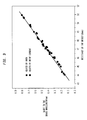
- Figure 3 shows the shift of the Bragg reflection as a function of measured resistance during operation of a device at various currents. It also shows the shift of the Bragg reflection as a function of resistance measured when a non-operating device is heated in a conventional bulk oven. The close agreement of the resistances measured in these two cases establishes the correspondence between the resistance measured during operation and actual temperature of the device.
- the temperature evaluated by measuring the resistance of the heater can be used in a conventional feedback-loop to control the current applied to the heater and, therefore, the temperature of the fiber.
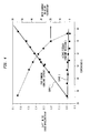
- Figure 4 illustrates in curve 1 the characteristics of a device operated at constant current (i.e. no feedback) and in curve 2 with feedback that controls the applied current to maintain a constant device resistance (i.e. temperature).
- the devices are highly sensitive to the temperature of its surroundings. When operated with feedback, however, the temperature sensitivity is eliminated.
- Figure 5 schematically illustrates a WDM optical fiber communication system 50 comprising a multiwavelength optical transmitter 51, segments of transmission fiber 52, one or more dispersion compensating grating device 53, and one or more optical fiber amplifiers 54. It also includes one or more multiwavelength optical receives 54. Long systems may also include one or more add/drop nodes (not shown) between successive transmission fiber segments 52.
- Typical dispersion compensating grating devices are described in United States Patent No. 4,953,939 issued to R.E. Epworth on September 4, 1990 and United States Patent No. 5,701,188 issued to M. Shigematsu et al. on December 23, 1997, which are incorporated herein by reference.
- the devices comprises linear arrays of chirped Bragg gratings arranged to reflect slower propagating wavelengths first and faster propagating wavelengths last, thereby compensating chromatic dispersion.
- One or more of the Bragg gratings in the array is advantageously stabilized against ambient changes as described in connection with Figures 1 and 2 herein.
- a typical optical fiber amplifier has a wavelength-dependent gain. This wavelength-dependence may be flattened by one or more long-period gratings. See United States Patent No. 5,430,817 issued to A.M. Vengsarkar on July 4, 1995, which is incorporated herein by reference. Each of the long period gratings is advantageously a thermally tunable grating and stabilized against ambient changes as described in connection with Figures 1 and 2 herein.
- add/drop nodes advantageously use thermally tunable Bragg gratings to control and route individual signal channels. See EP application no. 00301018.8.
- Bragg gratings are advantageously stabilized against ambient changes as described in connection with Figures 1 and 2 herein.
Landscapes
- Physics & Mathematics (AREA)
- General Physics & Mathematics (AREA)
- Optics & Photonics (AREA)
- Nonlinear Science (AREA)
- Optical Modulation, Optical Deflection, Nonlinear Optics, Optical Demodulation, Optical Logic Elements (AREA)
Abstract
In accordance with the invention, a thermally tunable optical waveguide device
is stabilized against ambient changes. Specifically, a feedback signal derived from a
temperature-dependent resistance is used to stabilize the device with respect to ambient
changes that could otherwise alter the temperature. Specific embodiments include
resistance-heated tunable gratings.
Description
- This invention relates to thermally tunable optical waveguide devices of enhanced stability and to optical communication systems employing them.
- Optical fiber communication systems are beginning to achieve their great potential for the rapid transmission of vast amounts of information. In essence, an optical fiber system comprises a light source, a modulator for impressing information on the light, an optical fiber transmission line for carrying the optical signals, and fiber amplifiers for amplifying the signals along the transmission path. It also includes a receiver for detecting the signals and for demodulating the information they carry. Increasingly, the optical signals are wavelength division multiplexed signals (WDM signals) comprising a plurality of distinct wavelength signal channels.
- Practical systems must also include a variety of tunable or switchable components for compensating the chromatic dispersion of transmitted signals, routing signals among different paths in the network and compensating nonlinear effects such as the wavelength-dependent gain fiber amplifiers.
- Thermally tunable waveguide devices are attractive for active routing, for compensation of dispersion and for flattening amplifier gain. The physical dimensions and refractive index of light-transmitting materials can be controllably varied by changing the temperature. This permits fine tuning of devices whose operating characteristics depend critically upon index and dimensions. For example, variation of the temperature can be used to tune the wavelength at which Bragg gratings will reflect, the wavelength of peak loss for long period gratings, and even the degree of chirp in a grating.
- Thermally tunable Bragg gratings essentially comprise lengths of optical waveguide including periodic perturbations in the refractive index which are spaced apart by a distance which is smaller than the transmitted wavelengths. A current-controlled thin-film resistive heater along the length of the grating can fine-tune the perturbation spacing, and thereby tune the reflected wavelength or the grating chirp. Such devices are described in greater detail in the following four articles which are incorporated herein by reference. (H.G. Limberger, N.H. Ky, D.M. Costantini, R.P. Salathe, C.A.P. Muller and G.R. Fox "Efficient Miniature Fiber-Optic Tunable Filter Based on Intracore Bragg Grating and Electrically Resistive Coating," IEEE Photonics Technology Letters 10(3), March 1998, p.361-363; G.R. Fox, C.A.P. Muller, N. Setter, D.M. Costantini, N.H. Ky and H.G. Limberger, "Wavelength Tunable Fiber Bragg Grating Devices Based on Sputter Deposited Resistive and Piezoelectric Coatings," Journal of Vacuum Science and Technology Part B, 15(3), May/June 1997, p. 1791-1795; B.J. Eggleton, J.A. Rogers, T.A. Strasser, "Optical Grating Devices With Adjustable Chirp," United States Patent Application, S.N. 09/183,048; K.R. Amundson, B.J. Eggleton, R.J. Jackman, J.A. Rogers and T.A. Strasser, "Thermally Adjustable Optical Fiber Grating Device With Packaging For Enhanced Performance, United States Application S.N. 09/252,708 filed February 2, 1999).
- Thermally tunable long period gratings similar to tunable Bragg gratings except that the perturbations are spaced apart by a distance which is larger than the transmitted wavelengths. They operate by controlling the loss of different modes of transmitted light. Thin film resistive heaters can control the wavelength of greatest loss or the grating chirp. Such devices are described in greater detail in the following two articles which are incorporated herein by reference. (D.M. Costantini, H.G. Limberger, R.P. Salathe, C.A.P. Muller and S.A. Vasiliev, "Tunable Loss Filter Based on Metal Coated Long Period Grating," Optical Fiber Conference Proceedings, 1998 and A.A. Abramov, B.J. Eggleton, J.A. Rogers, R.P. Espindola, A. Hale, R.S. Windeler and T.A. Strasser, "Electrically tunable efficient broadband long-period fiber grating filter," IEEE Photonics Technology Letters, 11(4), 445 (1999).
- As the desire for increased bandwidth requires additional and more closely spaced signal channels, the demands for stability of thermally tuned components becomes increasingly stringent. Because these components rely on heating, their operation can be affected by changes in ambient conditions such as temperature, humidity and air flow. Their operation can even be affected by the thermal mass of bulky temperature sensors. Even if the components are well isolated from their surroundings, they are sensitive to slight fluctuations in the thermal properties of their surroundings, and the more efficient they are, the greater the sensitivity. This sensitivity can produce undesirable changes in the transmitted signals.
- Accordingly there is a need for stabilized thermally tunable optical devices.
- In accordance with the invention, a thermally tunable optical waveguide device is stabilized against ambient changes. Specifically, a feedback signal derived from a temperature-dependent resistance is used to stabilize the device with respect to ambient changes that could otherwise alter the temperature. Specific embodiments include resistance-heated tunable gratings.
- The nature, advantages and various additional features of the invention will appear more fully upon consideration of the illustrative embodiments now to be described in detail in connection with the accompanying drawings. In the drawings:
- Fig. 1 is a schematic diagram of a thermally tunable optical waveguide device stabilized in accordance with the invention;
- Fig. 2 illustrates a specific embodiment of the component of Fig. 1 wherein the tunable device is a grating;
- Figs. 3 and 4 are graphical illustrations useful in understanding the operation of the invention; and
- Fig. 5 illustrates an optical communication system employing one or more devices in accordance with Fig. 1.
-
- It is to be understood that these drawings are for purposes of illustrating the concepts of the invention and, except for the graphs, are not to scale.
- Referring to the drawings, Fig. 1 is a schematic diagram of a thermally tunable
optical device 9 stabilized in accordance with the invention. Thedevice 9 comprises a length ofoptical waveguide 10 thermally sensitiveoptical element 11, anelectrical resistance heater 12 forheating element 11, a controllablecurrent source 13 for supplying current to theheater 12 and acontrol circuit 14 for controlling thecurrent source 13. - The
control circuit 14 advantageously comprises amicroprocessor controller 15 and a resistance detector 16 (ohmmeter). Theresistance detector 16 is coupled toresistance heater 12 to measure its resistance, and the output ofdetector 16 is supplied to thecontroller 15. Thecontroller 15 also receives a primary control signal indicative of a desired setting for the tunable optical device. - In typical embodiments, the
waveguide 10 will be an optical fiber or a planar waveguide. The thermally sensitiveoptical element 11 will comprise a grating, an amplifier, a resonance ring or a solid body resonance cavity. Theheater 12 can be a thin film resistance heater thermally coupled to theoptical element 11. - In operation, the temperature of
optical element 11 is primarily controlled by the primary control signal applied to thecontrol circuit 14. But ambient variations inducing temperature changes in theheater 12 produce changes in its temperature-dependent resistance. Thecontroller 15, supplied with these resistance changes, generates a negative feedback signal to the current source to stabilize the temperature against the ambient-induced variations. - In more complex components using a plurality of
elements 11, such as a serial array of Bragg gratings, asingle controller 15 can determine a plurality of feedback signals for a respective plurality ofelements 11. Similarly, asingle element 11 such as a long grating can use a plurality ofheaters 12 and asingle controller 15 can determine a respective plurality of feedback signals. - It is also possible to use one resistive element for the heater and a separate temperature-dependent resistive element for the temperature sensor, as by placing the heater and sensor in parallel stripes along the waveguide.
- Fig. 2 illustrates a specific embodiment of the Fig. 1 component wherein the thermally
tunable element 11 comprises a fiber grating 20 composed of a length ofoptical fiber 21 including a plurality spaced apart index perturbations 22. Theheater 12 is a thin resistive film disposed on the outer periphery of thefiber 21 overlying the perturbations. The grating 20 can be a Bragg grating or a long period grating depending on the spacing between perturbations. - The invention may now be understood by consideration of the following specific example.
- A tunable add/drop filter can be constructed using a uniform thin coating of 6000 Å Au/50 Å Ti on the cladding of a fiber that contains a conventional apodized Bragg grating. Passing current through the metal coating causes Joule heating of the fiber. This heating causes, primarily through the thermo-optic effect, a shift of the peak of the Bragg resonance. A package that consists of a thin plastic tube with rubber seals on its end provides some degree of isolation of the fiber from air currents, that can cause undesirable fluctuations in the temperature and, in turn, the optical characteristics of the device. Constructing a package that makes the operating temperature of the device completely independent of its surroundings is difficult.
- In order to allow long-term, stable operation and fast switching, we use the measured resistance of the coating to provide an accurate measurement of the temperature of the device. That is, the heater itself is used as a sensitive sensor of temperature. Figure 3 shows the shift of the Bragg reflection as a function of measured resistance during operation of a device at various currents. It also shows the shift of the Bragg reflection as a function of resistance measured when a non-operating device is heated in a conventional bulk oven. The close agreement of the resistances measured in these two cases establishes the correspondence between the resistance measured during operation and actual temperature of the device.
- The temperature evaluated by measuring the resistance of the heater can be used in a conventional feedback-loop to control the current applied to the heater and, therefore, the temperature of the fiber. Figure 4 illustrates in
curve 1 the characteristics of a device operated at constant current (i.e. no feedback) and incurve 2 with feedback that controls the applied current to maintain a constant device resistance (i.e. temperature). As the data indicate, without feedback, the devices are highly sensitive to the temperature of its surroundings. When operated with feedback, however, the temperature sensitivity is eliminated. - Figure 5 schematically illustrates a WDM optical
fiber communication system 50 comprising a multiwavelengthoptical transmitter 51, segments oftransmission fiber 52, one or more dispersion compensatinggrating device 53, and one or moreoptical fiber amplifiers 54. It also includes one or more multiwavelength optical receives 54. Long systems may also include one or more add/drop nodes (not shown) between successivetransmission fiber segments 52. - Typical dispersion compensating grating devices are described in United States Patent No. 4,953,939 issued to R.E. Epworth on September 4, 1990 and United States Patent No. 5,701,188 issued to M. Shigematsu et al. on December 23, 1997, which are incorporated herein by reference. The devices comprises linear arrays of chirped Bragg gratings arranged to reflect slower propagating wavelengths first and faster propagating wavelengths last, thereby compensating chromatic dispersion. One or more of the Bragg gratings in the array is advantageously stabilized against ambient changes as described in connection with Figures 1 and 2 herein.
- A typical optical fiber amplifier has a wavelength-dependent gain. This wavelength-dependence may be flattened by one or more long-period gratings. See United States Patent No. 5,430,817 issued to A.M. Vengsarkar on July 4, 1995, which is incorporated herein by reference. Each of the long period gratings is advantageously a thermally tunable grating and stabilized against ambient changes as described in connection with Figures 1 and 2 herein.
- In addition add/drop nodes advantageously use thermally tunable Bragg gratings to control and route individual signal channels. See EP application no. 00301018.8.
- Each of these Bragg gratings are advantageously stabilized against ambient changes as described in connection with Figures 1 and 2 herein.
- It is to be understood that the above-described embodiments are illustrative of only a few of the many possible specific embodiments which can represent applications of the principles of the invention. Numerous and varied other arrangements can be readily devised by those skilled in the art without departing from the scope of the invention.
Claims (7)
- A thermally tunable optical waveguide device comprising:a length of optical waveguide including a thermally sensitive optical element;a controllable heater for heating the thermally sensitive element;a temperature-dependent resistive element thermally coupled to the thermally sensitive element;a resistive detector coupled to the temperature-dependent resistive element; anda feedback circuit responsive to the output of the detector for providing a feedback signal to the controllable heater.
- A tunable device according to claim 1 wherein the controllable heater comprises an electrical resistance heating element and the temperature-dependent resistive element comprises the resistance heating element of the controllable heater.
- A tunable device according to claim 1 wherein the length of optical waveguide comprises a length of optical fiber.
- A tunable device according to claim 1 wherein the thermally sensitive optical element comprises an optical grating, optical ring resonator, waveguide amplifier or optical cavity.
- A tunable device according to claim 1 wherein the controllable heater comprises a coating of resistive material on the waveguide.
- A tunable device according to claim 1 wherein the feedback circuit provides a feedback signal for maintaining constant temperature.
- An optical communication system comprising a thermally tunable waveguide device according to claim 1.
Applications Claiming Priority (2)
| Application Number | Priority Date | Filing Date | Title |
|---|---|---|---|
| US325448 | 1989-03-17 | ||
| US09/325,448 US6438277B1 (en) | 1999-06-03 | 1999-06-03 | Stabilized thermally tunable optical waveguide devices and communication systems employing them |
Publications (1)
| Publication Number | Publication Date |
|---|---|
| EP1058144A2 true EP1058144A2 (en) | 2000-12-06 |
Family
ID=23267921
Family Applications (1)
| Application Number | Title | Priority Date | Filing Date |
|---|---|---|---|
| EP00304339A Withdrawn EP1058144A2 (en) | 1999-06-03 | 2000-05-23 | Stabilized thermally tunable optical waveguide devices and communication systems employing them |
Country Status (2)
| Country | Link |
|---|---|
| US (1) | US6438277B1 (en) |
| EP (1) | EP1058144A2 (en) |
Families Citing this family (21)
| Publication number | Priority date | Publication date | Assignee | Title |
|---|---|---|---|---|
| US6698769B2 (en) * | 1999-04-01 | 2004-03-02 | Heeling Sports Limited | Multi-wheel heeling apparatus |
| US6853671B2 (en) * | 2001-06-13 | 2005-02-08 | Intel Corporation | Method and apparatus for tuning a laser with a Bragg grating in a semiconductor substrate |
| US7088877B2 (en) * | 2001-06-13 | 2006-08-08 | Intel Corporation | Method and apparatus for tuning a bragg grating in a semiconductor substrate |
| US6856732B2 (en) * | 2001-06-13 | 2005-02-15 | Intel Corporation | Method and apparatus for adding/droping optical signals in a semiconductor substrate |
| US6879755B2 (en) * | 2001-07-25 | 2005-04-12 | Teraxion Inc. | Optical structure for the compensation of chromatic dispersion and dispersion slope in a light signal |
| US6941044B2 (en) * | 2001-07-25 | 2005-09-06 | Teraxion Inc. | Tunable optical structure for the compensation of chromatic dispersion in a light signal |
| US20030068130A1 (en) * | 2001-10-09 | 2003-04-10 | Photon-X, Inc. | Dynamic gain-equalizing filter based on polymer optical waveguide gratings |
| US6973231B2 (en) * | 2001-10-22 | 2005-12-06 | International Optics Communications Corporation | Waveguide grating-based wavelength selective switch actuated by thermal mechanism |
| US6707957B1 (en) * | 2001-12-18 | 2004-03-16 | Nortel Networks Limited | Compensating for polarisation mode dispersion in optical transmission fibers |
| US7062123B2 (en) * | 2001-12-31 | 2006-06-13 | 3M Innovative Properties Company | System for higher-order dispersion compensation |
| US6788727B2 (en) * | 2002-06-13 | 2004-09-07 | Intel Corporation | Method and apparatus for tunable wavelength conversion using a bragg grating and a laser in a semiconductor substrate |
| US6950577B2 (en) * | 2002-07-01 | 2005-09-27 | Intel Corporation | Waveguide-based Bragg gratings with spectral sidelobe suppression and method thereof |
| US7245792B2 (en) * | 2002-08-16 | 2007-07-17 | Intel Corporation | Silicon-based tunable single passband optical filter |
| US20040264834A1 (en) * | 2003-06-26 | 2004-12-30 | Mcintyre Thomas J. | Feedback controlled photonic frequency selection circuit |
| US11464451B1 (en) | 2020-03-11 | 2022-10-11 | Huxley Medical, Inc. | Patch for improved biometric data capture and related processes |
| US11660005B1 (en) | 2021-06-04 | 2023-05-30 | Huxley Medical, Inc. | Processing and analyzing biometric data |
| US12575741B1 (en) | 2024-04-15 | 2026-03-17 | Huxley Medical, Inc. | Systems and processes for detecting oxygen saturation and compensating for skin tone variation |
| US12178552B1 (en) | 2021-06-04 | 2024-12-31 | Huxley Medical, Inc. | Systems and processes for detecting oxygen saturation and compensating for skin tone variation |
| US12279853B1 (en) | 2021-08-24 | 2025-04-22 | Huxley Medical, Inc. | Photoplethysmography sensors and processes |
| US12114980B1 (en) | 2021-08-24 | 2024-10-15 | Huxley Medical, Inc. | Photoplethysmography sensors and processes |
| USD1123167S1 (en) | 2024-09-09 | 2026-04-21 | Huxley Medical, Inc. | Wearable medical device |
Family Cites Families (6)
| Publication number | Priority date | Publication date | Assignee | Title |
|---|---|---|---|---|
| US5159601A (en) * | 1991-07-17 | 1992-10-27 | General Instrument Corporation | Method for producing a tunable erbium fiber laser |
| US5579143A (en) * | 1993-06-04 | 1996-11-26 | Ciena Corporation | Optical system with tunable in-fiber gratings |
| US5502782A (en) * | 1995-01-09 | 1996-03-26 | Optelecom, Inc. | Focused acoustic wave fiber optic reflection modulator |
| US6078418A (en) * | 1997-08-12 | 2000-06-20 | Lucent Technologies Inc. | Wavelength locking of variable dispersive elements |
| JPH1184324A (en) * | 1997-09-05 | 1999-03-26 | Fujitsu Ltd | Method, apparatus and system for optical modulation in wavelength division multiplexing |
| US5987200A (en) * | 1997-10-27 | 1999-11-16 | Lucent Technologies Inc. | Device for tuning wavelength response of an optical fiber grating |
-
1999
- 1999-06-03 US US09/325,448 patent/US6438277B1/en not_active Expired - Lifetime
-
2000
- 2000-05-23 EP EP00304339A patent/EP1058144A2/en not_active Withdrawn
Also Published As
| Publication number | Publication date |
|---|---|
| US6438277B1 (en) | 2002-08-20 |
Similar Documents
| Publication | Publication Date | Title |
|---|---|---|
| US6438277B1 (en) | Stabilized thermally tunable optical waveguide devices and communication systems employing them | |
| US5987200A (en) | Device for tuning wavelength response of an optical fiber grating | |
| US6728445B2 (en) | Closed-loop control of tunable optical wavelength filters | |
| US6411746B1 (en) | Thermally tunable optical devices | |
| US6256428B1 (en) | Cascading of tunable optical filter elements | |
| EP1455218B1 (en) | Thermally tunable fiber devices with microcapillary heaters | |
| EP1055143B1 (en) | Cascading of tunable optical filter elements | |
| EP0989422B1 (en) | Tapered optical fiber devices with variable index coatings for modifying guide properties of the fundamental mode | |
| CN100419477C (en) | Optical waveguide device, variable optical attenuator and its array, optical switch and its array | |
| US6738543B1 (en) | Hitless tunable wavelength filters | |
| US20030161580A1 (en) | Optical structure for the compensation of chromatic dispersion and dispersion slope in a light signal | |
| Dabarsyah et al. | Adjustable dispersion-compensation devices with wavelength tunability based on enhanced thermal chirping of fiber Bragg gratings | |
| US6856731B2 (en) | Heat tunable optical devices with linearity compensation | |
| EP1994434A2 (en) | Dynamically tunable waveguide chip for optical transforms | |
| Lyons et al. | An electrically tunable all-fiber polarization controller based on deposited thin-film microheaters | |
| US7711222B2 (en) | Tunable dispersion compensation apparatus | |
| Rogers et al. | Temperature stabilised operation of tunable fibre grating devices that use distributed on-fibre thin film heaters | |
| Eggleton et al. | Temperature stabilized tunable fiber grating devices with integrated on-fiber thin film heaters | |
| US7231150B2 (en) | Method and apparatus for sensing a temperature along an optical path in semiconductor material | |
| KR20070056562A (en) | Optical time delay interferometer with phase variable function | |
| JP2004117966A (en) | Waveguide optical element having optical output control function and its optical output control method | |
| Eggleton et al. | Tunable fiber grating devices utilizing integrated thin film heaters | |
| US6970635B2 (en) | Method of and apparatus for setting apparent length of optical fiber | |
| EP1158341A2 (en) | Optical switch | |
| JP2003195192A (en) | Dispersion compensator |
Legal Events
| Date | Code | Title | Description |
|---|---|---|---|
| PUAI | Public reference made under article 153(3) epc to a published international application that has entered the european phase |
Free format text: ORIGINAL CODE: 0009012 |
|
| AK | Designated contracting states |
Kind code of ref document: A2 Designated state(s): AT BE CH CY DE DK ES FI FR GB GR IE IT LI LU MC NL PT SE |
|
| AX | Request for extension of the european patent |
Free format text: AL;LT;LV;MK;RO;SI |
|
| STAA | Information on the status of an ep patent application or granted ep patent |
Free format text: STATUS: THE APPLICATION HAS BEEN WITHDRAWN |
|
| 18W | Application withdrawn |
Effective date: 20030319 |