EP1058137A2 - Method of manufacturing polarization-maintaining optical fiber coupler - Google Patents
Method of manufacturing polarization-maintaining optical fiber coupler Download PDFInfo
- Publication number
- EP1058137A2 EP1058137A2 EP00304564A EP00304564A EP1058137A2 EP 1058137 A2 EP1058137 A2 EP 1058137A2 EP 00304564 A EP00304564 A EP 00304564A EP 00304564 A EP00304564 A EP 00304564A EP 1058137 A2 EP1058137 A2 EP 1058137A2
- Authority
- EP
- European Patent Office
- Prior art keywords
- polarization
- maintaining optical
- polarized wave
- optical fiber
- optical fibers
- Prior art date
- Legal status (The legal status is an assumption and is not a legal conclusion. Google has not performed a legal analysis and makes no representation as to the accuracy of the status listed.)
- Granted
Links
Images



Classifications
-
- G—PHYSICS
- G02—OPTICS
- G02B—OPTICAL ELEMENTS, SYSTEMS OR APPARATUS
- G02B6/00—Light guides; Structural details of arrangements comprising light guides and other optical elements, e.g. couplings
- G02B6/24—Coupling light guides
- G02B6/26—Optical coupling means
-
- G—PHYSICS
- G02—OPTICS
- G02B—OPTICAL ELEMENTS, SYSTEMS OR APPARATUS
- G02B6/00—Light guides; Structural details of arrangements comprising light guides and other optical elements, e.g. couplings
- G02B6/24—Coupling light guides
- G02B6/26—Optical coupling means
- G02B6/28—Optical coupling means having data bus means, i.e. plural waveguides interconnected and providing an inherently bidirectional system by mixing and splitting signals
- G02B6/2804—Optical coupling means having data bus means, i.e. plural waveguides interconnected and providing an inherently bidirectional system by mixing and splitting signals forming multipart couplers without wavelength selective elements, e.g. "T" couplers, star couplers
- G02B6/2821—Optical coupling means having data bus means, i.e. plural waveguides interconnected and providing an inherently bidirectional system by mixing and splitting signals forming multipart couplers without wavelength selective elements, e.g. "T" couplers, star couplers using lateral coupling between contiguous fibres to split or combine optical signals
- G02B6/2835—Optical coupling means having data bus means, i.e. plural waveguides interconnected and providing an inherently bidirectional system by mixing and splitting signals forming multipart couplers without wavelength selective elements, e.g. "T" couplers, star couplers using lateral coupling between contiguous fibres to split or combine optical signals formed or shaped by thermal treatment, e.g. couplers
-
- G—PHYSICS
- G02—OPTICS
- G02B—OPTICAL ELEMENTS, SYSTEMS OR APPARATUS
- G02B6/00—Light guides; Structural details of arrangements comprising light guides and other optical elements, e.g. couplings
- G02B6/24—Coupling light guides
- G02B6/26—Optical coupling means
- G02B6/28—Optical coupling means having data bus means, i.e. plural waveguides interconnected and providing an inherently bidirectional system by mixing and splitting signals
- G02B6/2804—Optical coupling means having data bus means, i.e. plural waveguides interconnected and providing an inherently bidirectional system by mixing and splitting signals forming multipart couplers without wavelength selective elements, e.g. "T" couplers, star couplers
- G02B6/2821—Optical coupling means having data bus means, i.e. plural waveguides interconnected and providing an inherently bidirectional system by mixing and splitting signals forming multipart couplers without wavelength selective elements, e.g. "T" couplers, star couplers using lateral coupling between contiguous fibres to split or combine optical signals
- G02B6/2843—Optical coupling means having data bus means, i.e. plural waveguides interconnected and providing an inherently bidirectional system by mixing and splitting signals forming multipart couplers without wavelength selective elements, e.g. "T" couplers, star couplers using lateral coupling between contiguous fibres to split or combine optical signals the couplers having polarisation maintaining or holding properties
Definitions
- the present invention provides a novel polarization-maintaining optical fiber coupler which is useful in the optical fiber communication field, the field of sensors using optical fibers and the like, and which couples and branches lights while maintaining the polarization of light in optical fibers.
- the mode of light is comprised of an X polarized wave and Y polarized wave.
- a device which can couple and branch those polarized waves is called a polarization beam splitter (hereinafter abbreviated to "PBS").
- PBS polarization beam splitter
- a PBS is useful, for example, in a fiber optic gyro which measures the angular velocity using, for example, the interference of light or in coupling and branching lights from a light source which has linear polarization.
- the X polarized wave and Y polarized wave should have different coupling characteristics.
- a polarization-maintaining optical fiber coupler which uses polarization-maintaining optical fibers.
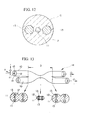
- FIG. 12 exemplifies a PANDA fiber.
- This PANDA fiber 10 comprises a core 11 provided at the center, a cladding 12 provided concentrical to the core 11 and having a lower refractive index than that of the core 11, and two stress applying sections 13 arranged in the cladding 12 symmetrically to each other around the core 11 and having a circular cross section and a lower refractive index than the cladding 12.
- the core 11 is formed of germanium-doped quartz glass
- the cladding 12 is formed of pure quartz glass
- each stress applying section 13 is formed of quartz glass in which a relatively large amount of boron is doped.
- the outside diameter of the core 11, the outside diameter of the stress applying section 13, the relative refractive-index difference between the core 11 and the cladding 12, and the relative refractive-index difference between the cladding 12 and the stress applying section 13 are adequately set in accordance with the desired characteristics.
- the outside diameter of the cladding 12 is normally set to approximately 125 ⁇ m.
- the stress applying section 13 has a larger coefficient of thermal expansion than the cladding 12. In the process where the optical fiber drawn at the time of production is cooled, strain originated at the stress applying section 13 is applied to the fiber's cross section.
- This strain produces anisotropic strain with respect to the core 11, clearing the degeneracy of polarized waves so that the propagation constant of the X polarized wave differs from that of the Y polarized wave. Naturally, the distributions of the electromagnetic fields of those polarized waves differ from each other. This provides the characteristic such that the X polarized wave and Y polarized wave are maintained while propagating.
- FIG. 13 exemplifies a polarization-maintaining optical fiber coupler.
- This polarization-maintaining optical fiber coupler 14 has two PANDA fibers 10 arranged side by side in such a way that their axes of polarization become parallel to each other.
- the PANDA fibers 10 are heated and melted with claddings 12 midways of the PANDA fibers 10 and are elongated in the lengthwise direction, thus forming a fused-elongated section (optical coupling section) 3.
- the axis of polarization is the line in each PANDA fiber 10 that passes the center between the stress applying sections 13.
- the X polarized wave propagates while maintaining the electric field vector in the direction of the polarization axes of the PANDA fibers 10, while the Y polarized wave propagates in the PANDA fibers 10 while maintaining the electric field vector in the direction perpendicular to the direction of the former electric field vector.
- the X polarized wave and Y polarized wave are coupled or branched at the fused-elongated section 3 at a midway.
- the difference between the coupling ratio of the X polarized wave and that of the Y polarized wave can be provided by making long the elongation length, namely the length by which the optical fiber (PANDA fiber 10) is to be elongated at the time the fused-elongated section 3 is formed.
- This difference can provide the conventional polarization-maintaining optical fiber coupler with the characteristics of a PBS.
- FIG. 14A is a graph showing the relationship between the elongation length and the coupling ratio of light having a wavelength in use.
- the broken line represents the coupling characteristic of the X polarized wave, and the solid line the coupling characteristic of the Y polarized wave.
- Forming the fused-elongated section of the conventional polarization-maintaining optical fiber coupler involves the repetition of an operation of coupling both the X polarized wave and Y polarized wave from one polarization-maintaining optical fiber (first optical fiber) to the other polarization-maintaining optical fiber (second optical fiber), further proceeding elongation to thereby transfer (couple) both polarized waves to the first optical fiber, and then transferring the polarized waves to the second optical fiber.
- the coupling of the Y polarized wave is slightly larger than the coupling of the X polarized wave, thus providing a slight difference between the cyclic changes (transfer cyclic changes) in the coupling ratios of the Y polarized wave and the X polarized wave.
- one cycle is taken as a change in the coupling ratio which starts increasing from 0%, reaches 100%, then decreases to 0%, and two cycles are simply the repetition of one cycle twice.
- the difference between the coupling ratios of the X polarized wave and the Y polarized wave becomes larger. If the fused-elongated section 3 is formed, elongated to the vicinity of the point where the difference in the coupling ratio indicated by the thick arrow in the graph becomes large, it is possible to acquire the characteristics of a PBS such that when the X polarized wave and Y polarized wave of the wavelength in use are input from the input-side port which is comprised of the same fiber as an output-side port A, the X polarized wave is output from the output-side port A and the Y polarized wave is output from the other port B.
- the conventional polarization-maintaining optical fiber coupler however suffers the problem of the long device length needed to couple and branch the X polarized wave and the Y polarized wave.
- the elongation length would become more than 60 mm and would become as long as about 100 mm in some cases.
- the wavelength band that permits coupling and branching of the X polarized wave and Y polarized wave is extremely narrow, for example, as narrow as about 10 nm.
- a method of manufacturing a polarization-maintaining optical fiber coupler which comprises the steps of heating lengthwise portions of two polarization-maintaining optical fibers extending side by side; and elongating the heated portions to thereby form a fused-elongated section, wherein elongation is terminated when the cyclic changes in a coupling ratio of two polarized waves according to an elongation length at a wavelength in use are both within first two cycles, so that the coupling ratio of one of the polarized waves is equal to or less than 10% and the coupling ratio of the other one of the polarized waves is equal to or greater than 90%.
- This invention has the following advantages.
- This invention can provide a polarization-maintaining optical fiber coupler whose coupling ratio has a large dependency on polarization with a short elongation length. It is therefore effective to use this polarization-maintaining optical fiber to prepare a PBS.
- the short elongation length can permit the polarization-maintaining optical fiber coupler to have a large mechanical strength. Further, it is possible to reduce the number of times the X polarized wave or Y polarized wave is coupled from one polarization-maintaining optical fiber to the other one (the number of transfer times), thus resulting in a low loss.
- this invention can provide a polarization-maintaining optical fiber coupler whose coupling ratio has a large polarization dependency over a wide wavelength band. It is therefore possible to provide a PBS effective in preparing an optical circuit which, for example, simultaneously separates light of multiple wavelengths to different polarized waves or couple polarized waves.
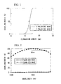
- FIG. 1 is a graph showing the relationship between the elongation length at the time of forming a fused-elongated section and the coupling ratio of light with a wavelength of 1550 nm (used wavelength) according to the first embodiment.
- the polarization-maintaining optical fibers used in this embodiment are PANDA fibers that have the following characteristics.
- (Characteristics of PANDA Fibers) Core diameter (core radius) 6.5 ⁇ m (3.25 ⁇ m) Cladding diameter 125 ⁇ m Core-cladding relative refractive-index difference 0.35% Outside diameter of stress applying section 35 ⁇ m Distance between centers of stress applying sections 55 ⁇ m Diameter A 20 ⁇ m Used wavelength 1550 nm Mode birefringent index at used wavelength 4 x 10 -4
- the minimum diameter of the fused-elongated section of the obtained polarization-maintaining optical fiber coupler is 61 ⁇ m, the aspect ratio is 1.89 and the elongation length is 17.8 mm.
- the aspect ratio is the ratio of the maximum outside diameter of the center portion of the fused-elongated section to the minimum outside diameter thereof (maximum outside diameter/minimum outside diameter).
- the fused-elongated section is formed by heating and melting two polarization-maintaining optical fibers in such a way that the cores of the two polarization-maintaining optical fibers do not come close to each other to the greatest extent possible (in such a way that the distance between the centers of the cores does not becomes too small).
- This can provide a large difference between the coupling ratios of the X polarized wave and Y polarized wave from the point at which the coupling ratios start increasing.
- Adjusting the degree of closeness of two cores at the fused-elongated section this way can provide a sufficient difference between the coupling ratios of the X polarized wave and Y polarized wave over a wide wavelength range as shown in FIG. 2.
- the wavelength range over which the coupling ratio of the Y polarized wave is equal to or greater than 90% and the coupling ratio of the X polarized wave is equal to or smaller than 10% is 58 nm which is very wide. Because the coupling ratio of the X polarized wave rises slightly on the long wavelength side, the dependency of the X polarized wave on the wavelength is smaller on the short wavelength side.
- heating conditions it is preferable to set such heating conditions as to permit easy maintenance of the outward form of two polarization-maintaining optical fibers so that the centers of the cores of those two optical fibers do not come too close to each other.
- One feasible way is to set the temperature of the heating source, such as a burner, lower than the conventional temperature.
- Another way is to increase the distance from the heating source. Further, elongation may be carried out quickly so as to reduce the amount of heat per unit time.
- light of the used wavelength is input from the input-side port and heating and elongation are carried out while monitoring the lights that emitted from two ports on the output side, and the work is terminated when the desired coupling ratio is acquired.
- FIG. 3 presents a graph showing the relationship between the elongation length at the time of forming a fused-elongated section and the coupling ratio of light with a wavelength of 1550 nm (used wavelength) according to the second embodiment.
- the fused-elongated section is formed by heating and melting two polarization-maintaining optical fibers in such a way that the cores of the two polarization-maintaining optical fibers do not come close to each other to the greatest extent possible. This permits the distance between the centers of the two cores to be kept at the fused-elongated section and provides a large difference between the coupling ratios of the X polarized wave and Y polarized wave from the point at which the coupling ratios start increasing.
- elongation is stopped for the Y polarized wave at the point of time (1 cycle) where the coupling ratio increased and has reached 100% once and then decreased and has reached 0%.
- elongation is stopped at the point of time (1/2 cycle) when the coupling ratio has reached 100% for the first time.
- the second embodiment can also provide a difference between the coupling ratios of the X polarized wave and the Y polarized wave over a wide wavelength band as shown in FIG. 4.
- the minimum diameter of the fused-elongated section of this polarization-maintaining optical fiber coupler is 41 ⁇ m, the aspect ratio is 1.98 and the elongation length is 24.2 mm.
- the wavelength range over which the coupling ratio of the X polarized wave is equal to or greater than 90% and the coupling ratio of the Y polarized wave is equal to or smaller than 10% is 35 nm which is more than triple the conventional range of about 10 nm.
- Polarization-maintaining optical fibers suitable for this invention will now be discussed.
- FIG. 5 is a cross-sectional view exemplifying a polarization-maintaining optical fiber suitable for this invention.
- the polarization-maintaining optical fiber of this example is a PANDA fiber.
- This PANDA fiber is characterized in that the distance between the stress applying sections 13 is large. This distance is determined based on the diameter A of the largest circle 15 which is concentric to the core 11 or the cladding 12, does not reach the stress applying sections 13 and does not include the stress applying sections 13.
- the diameter A is equal to or greater than 20 ⁇ m, preferably 25 to 30 ⁇ m.
- the excess loss tends to become larger.
- the diameter A exceeds 30 ⁇ m, the difference between the propagation constant of the X polarized wave and that of the Y polarized wave becomes small. This deteriorates the crosstalk between the X polarized wave and Y polarized wave (polarization crosstalk), which may degrade the retained states of the X polarized wave and Y polarized wave.
- the diameter A of polarization-maintaining optical fibers for ordinary communications or the like is about 12 to 17 ⁇ m.
- the stress applying sections 13 are set apart as mentioned above, by way of contrast, the stress that is applied to the core 11 by the stress applying sections 13 decreases and the birefringent index becomes lower as compared with that of the ordinary polarization-maintaining optical fibers.
- the crosstalk between the fast axis (Y polarization axis) and the slow axis (X polarization axis), i.e., the X-Y polarization crosstalk tends to be degraded.
- the loss may become slightly greater.
- the birefringent index of polarization-maintaining optical fibers suitable for this invention is in a range of 5 x 10 -5 to 5 x 10 -4
- the birefringent index of ordinary polarization-maintaining optical fibers for communications or the like is about 5 x 10 -4 .
- the crosstalk per unit length is equal to or greater than -20 dB/km, and is substantially in a range of -20 dB/km to -10 dB/km.
- the crosstalk of ordinary polarization-maintaining optical fibers is approximately -25 dB/km.
- the loss per unit length is equal to or greater than 1 dB/km.
- the loss is substantially in a range of 1 to 10 dB/km.
- the loss of ordinary polarization-maintaining optical fibers is approximately 0.2 to 0.3 dB/km.
- the length of the lead fibers of the polarization-maintaining optical fiber using the instant polarization-maintaining optical fibers be set to 10 m or shorter.
- the length of the lead fibers is substantially set to 0.5 to 10 m.
- the "lead fibers" are two polarization-maintaining optical fibers (PANDA fibers) 10 which extend out from both ends of the fused-elongated section 3 to constitute the input/output ports as shown in FIG. 13.
- PANDA fibers polarization-maintaining optical fibers
- the core 11, cladding 12 and stress applying sections 13 are formed of, for example, the same materials as those of the conventional polarization-maintaining optical fiber coupler.
- the outside diameter of the stress applying section 13, the relative refractive-index difference between the core 11 and the cladding 12 and the relative refractive-index difference between the cladding 12 and the stress applying section 13 are adequately designed according to the desired characteristics.
- the mode field diameter of the core 11 is set to about 4 to 10 ⁇ m though it varies depending on the diameter of the core and the used wavelength.
- the outside diameter of the cladding 12 is set to about 125 ⁇ m.
- FIG. 6 presents a graph showing the relationship between the elongation length at the time of forming a fused-elongated section and the coupling ratio of light with a wavelength of 980 nm (used wavelength) according to the third embodiment.
- elongation is stopped for the Y polarized wave at the point in time (1/2 cycle) when the coupling ratio has reached 100% for the first time after the coupling ratio begins to increase, and elongation is stopped for the X polarized wave at the point in time when the coupling ratio increases very little.
- FIG. 7 shows changes in the excess losses of the X polarized wave and the Y polarized wave in accordance with an increase in the elongation length. It is apparent that the excess loss of the X polarized wave hardly changes while the excess loss of the Y polarized wave increases once, then decreases to near zero.
- the point at which the coupling ratio of the Y polarized wave is sufficiently increased coincides with the point at which the excess loss of the Y polarized wave comes close to zero.
- This third embodiment can also realize the difference between the coupling ratios of the X polarized wave and the Y polarized wave over a wide wavelength range as shown in FIG. 8.
- the minimum diameter of the fused-elongated section is 58 ⁇ m, the aspect ratio is 1.92 and the elongation length is 22 mm.
- FIG. 9 is a graph showing the relationship between the elongation length at the time a polarization-maintaining optical fiber coupler is manufactured as in the third embodiment using ordinary PANDA fibers with a small diameter A as presented below and the coupling ratio of light with a wavelength of 980 nm (used wavelength).
- FIG. 10 is a graph showing the relationship between the elongation length and the excess losses of the X polarized wave and Y polarized wave in this example.
- the excess loss of the X polarized wave hardly changes while the excess loss of the Y polarized wave greatly increases, then decreases but increases again before it reaches near zero in FIG. 10.
- the coupling ratio is influenced by a variation in this excess loss and repeatedly increments and decrements.
- the excess loss of the Y polarized wave cannot be made to come close to zero, it is therefore inevitable that the characteristics of the polarization-maintaining optical fiber coupler of this example are inferior to those of the polarization-maintaining optical fiber couplers of the first to third embodiments regardless of under what conditions the elongation is stopped.
- the coupling ratio for one of the polarized waves be equal to or lower than 10%
- the coupling ratio for the other polarized wave be equal to or greater than at least 90%
- the wavelength band over which those coupling ratios are maintained be equal to or greater than at least 30 nm.
- polarization-maintaining optical fibers whose diameter A is equal to or greater than 20 ⁇ m can provide a polarization-maintaining optical fiber coupler which has a small excess loss.
- Those coupling ratio ranges can be set by inputting light of the used wavelength to one of the polarization-maintaining optical fibers at the time of forming the fused-elongated section, monitoring the coupling ratios of the two polarized waves and stopping the work when the desired characteristics are attained, as mentioned above.
- the wavelength band if narrower than 30 nm, increases the wavelength dependency of the coupling ratios of the polarization, thus limiting the used wavelength.
- the used wavelength should preferably lie in a range of 0.6 to 1.7 ⁇ m which is the wavelength band where a polarization-maintaining optical fiber coupler is normally used. It is also preferable that the wavelength band should lie within this range.
- this invention is not limited to the use of such a type, but can use other polarization-maintaining optical fibers such as a bow tie fiber, an elliptic jacket fiber as well.
- the loss due to the absorption by the stress applying sections 13 becomes preferably small if the portions other than the cladding 12 such as the stress applying sections 13 are not positioned between the cores 11 as much as possible, as indicated by the cross section in FIG 13. It is most desirable that the two polarization axes be parallel to each other as shown in the cross-sectional view.
- this invention can provide a polarization-maintaining optical fiber coupler which has a large polarization dependency of the coupling ratio at a short elongation length. It is therefore effective to prepare a PBS. Further, the short elongation length can improve the mechanical strength.
- the loss is small because the number of times the X polarized wave or Y polarized wave is coupled from one polarization-maintaining optical fiber to the other (the number of transfers) can be reduced.
- P A (Z) and P B (Z) of the propagated light, at a positive Z in the lengthwise direction of the two optical fibers in an optical fiber coupler are expressed by the following Equation 1.
- P A (Z) 1 - Fsin 2 (qz)
- P B (Z) Fsin 2 (qz)
- Equation 1 is simplified to Equation 2 below.
- P A (Z) 1 - sin 2 ( ⁇ z)
- P B (Z) sin 2 ( ⁇ z)
- Equation 2 For polarization-maintaining optical fibers, Equation 2 is satisfied for both the X polarized wave and Y polarized wave. At this time, if the coupling coefficient ⁇ does not depend on polarization for the polarization direction, the coupling characteristic that depends on polarization cannot be obtained at a predetermined wavelength.
- FIG. 11A presents a graph indicating that ⁇ depends on the structure of optical fibers (reference document: "Fundamental of Optical Waveguide” by Katsunari Okamoto, p 151, in Photonics Series by CORONA Publishing Co., Ltd.).
- V in the graph is the normalized frequency of the core of an optical fiber, which is given by the following Equation 3.
- V (2 ⁇ / ⁇ )an 1 (2 ⁇ ) 1 ⁇ 2
- a the radius of the core
- this graph is for the case where the normal frequencies V of two optical fibers are equal to each other. It is apparent from FIG. 11A that the coupling coefficient K varies greatly according to the normalized frequency V.
- the normalized frequency V should take a value that guarantees single-mode propagation for the optical fibers that constitute an optical fiber coupler.
- the single-mode condition is considered for each polarized wave.
- the normalized frequency V X of the X polarized wave is 1.6
- the normalized frequency V Y of the Y polarized wave is 1.4
- the coupling coefficient of the X polarized wave takes a value about 10 times larger than that of the Y polarized wave.
- the Y polarized wave is coupled 100% to the port B.
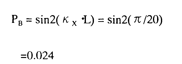
- the following shows the value of the ratio of the power of the X polarized wave that is output from the port B when the power of the input X polarized wave is taken as 1.
Landscapes
- Physics & Mathematics (AREA)
- General Physics & Mathematics (AREA)
- Optics & Photonics (AREA)
- Optical Fibers, Optical Fiber Cores, And Optical Fiber Bundles (AREA)
- Mechanical Coupling Of Light Guides (AREA)
Abstract
Description
| (Characteristics of PANDA Fibers) | |
| Core diameter (core radius) | 6.5 µm (3.25 µm) |
| Cladding diameter | 125 µm |
| Core-cladding relative refractive-index difference | 0.35% |
| Outside diameter of stress applying section | 35 µm |
| Distance between centers of stress applying sections | 55 µm |
| Diameter A | 20 µm |
| Used wavelength | 1550 nm |
| Mode birefringent index at used wavelength | 4 x 10⁻⁴ |
| Excess loss (1550 nm) | X polarized wave | 0.12 dB |
| Y polarized wave | 0.33 dB | |
| Coupling ratio (1550 nm) | X polarized wave | 0.9% |
| Y polarized wave | 99.2% | |
| 90% band of Y polarized wave | 58 nm | |
| 15% band of X polarized wave | 1600 nm or lower |
| Excess loss (1550 nm) | X polarized wave | 0.14 dB |
| Y polarized wave | 0.45 dB | |
| Coupling ratio (1550 nm) | X polarized wave | 99.1% |
| Y polarized wave | 1.1% | |
| 90% band of X polarized wave | 35 nm | |
| 15% band of Y polarized wave | 43 nm |
| Excess loss (980 nm) | X polarized wave | 0.10 dB |
| Y polarized wave | 0.38 dB | |
| Coupling ratio (980 nm) | X polarized wave | 0.1% |
| Y polarized wave | 99.6% | |
| 90% band of Y polarized wave | 36 nm | |
| 15% band of X polarized wave | 1200 nm or lower |
| (Characteristics of PANDA Fibers) | |
| Core diameter (core radius) | 6.5 µm (3.25 µm) |
| Cladding diameter | 125 µm |
| Relative refractive-index difference between core claddings | 0.35% |
| Outside diameter of stress applying section | 35 µm |
| Distance between centers of stress applying sections | 51 µm |
| Diameter A | 16 µm |
| Used wavelength | 980 nm |
| Mode birefringent index at used wavelength | 5 x 10⁻⁴ |
Claims (13)
- A method of manufacturing a polarization-maintaining optical fiber coupler, comprising the steps of:heating lengthwise portions of two polarization-maintaining optical fibers extending side by side; andelongating said heated portions to thereby form a fused-elongated section, wherein elongation is terminated when the cyclic changes in a coupling ratio of two polarized waves according to an elongation length at a wavelength in use are both within first two cycles, so that said coupling ratio of one of said polarized waves is equal to or less than 10% and said coupling ratio of the other one of said polarized waves is equal to or greater than 90%.
- The method according to claim 1, wherein said fused-elongated section is formed by holding cores of said two polarization-maintaining optical fibers as far apart from each other as possible, thereby increasing a difference between said coupling ratios of said two polarized waves from a point at which optical coupling occurs.
- The method according to claim 1, wherein a wavelength band that permits said coupling ratio of one of said polarized waves to be kept equal to or less than 10% and said coupling ratio of the other one of said polarized waves to be kept equal to or greater than 90% is equal to or greater than 30 nm.
- The method according to claim 1, wherein each of said polarization-maintaining optical fibers has stress applying sections arranged symmetrically to each other with respect to a core in a cladding surrounding said core; and
the largest one of those concentric circles of said core which do not reach said stress applying sections and do not include said stress applying sections within has a diameter of 20 µm or greater. - The method according to claim 4, wherein said diameter is in a range of 25 to 30 µm.
- The method according to claim 4, wherein said polarization-maintaining optical fibers have a birefringent index of 5 x 10⁻⁵ to 5 x 10⁻⁴.
- The method according to claim 4, wherein a crosstalk of said polarization-maintaining optical fibers is equal to or greater than -20 dB/km.
- The method according to claim 7, wherein said crosstalk of said polarization-maintaining optical fibers is in a range of -20 to -10 dB/km.
- The method according to claim 4, wherein a loss of said polarization-maintaining optical fibers is equal to or greater than 1 dB/km.
- The method according to claim 9, wherein said loss of said polarization-maintaining optical fibers is in a range of 1 to 10 dB/km.
- The method according to claim 4, wherein a lead fiber of said polarization-maintaining optical fiber coupler has a length of 10 m or shorter.
- The method according to claim 11, wherein said length of said lead fiber of said polarization-maintaining optical fiber coupler is in a range of 0.5 to 10 m.
- The method according to claim 1, wherein said polarization-maintaining optical fibers are PANDA type polarization-maintaining optical fibers.
Applications Claiming Priority (2)
| Application Number | Priority Date | Filing Date | Title |
|---|---|---|---|
| JP15308099 | 1999-05-31 | ||
| JP15308099 | 1999-05-31 |
Publications (3)
| Publication Number | Publication Date |
|---|---|
| EP1058137A2 true EP1058137A2 (en) | 2000-12-06 |
| EP1058137A3 EP1058137A3 (en) | 2003-03-12 |
| EP1058137B1 EP1058137B1 (en) | 2007-03-07 |
Family
ID=15554551
Family Applications (1)
| Application Number | Title | Priority Date | Filing Date |
|---|---|---|---|
| EP00304564A Expired - Lifetime EP1058137B1 (en) | 1999-05-31 | 2000-05-30 | Method of manufacturing polarization-maintaining optical fiber coupler |
Country Status (8)
| Country | Link |
|---|---|
| US (1) | US6463195B1 (en) |
| EP (1) | EP1058137B1 (en) |
| KR (1) | KR100786617B1 (en) |
| CN (1) | CN1149414C (en) |
| AU (1) | AU774103B2 (en) |
| CA (1) | CA2309564C (en) |
| DE (1) | DE60033732T2 (en) |
| TW (1) | TW440723B (en) |
Families Citing this family (15)
| Publication number | Priority date | Publication date | Assignee | Title |
|---|---|---|---|---|
| JP2001056416A (en) * | 1999-08-20 | 2001-02-27 | Fujikura Ltd | Polarization maintaining optical fiber and polarization maintaining optical fiber component |
| JP2002296438A (en) * | 2001-03-29 | 2002-10-09 | Fujikura Ltd | Polarization-maintaining optical fiber and method of manufacturing base material thereof |
| US7085461B2 (en) * | 2001-04-30 | 2006-08-01 | Verrillon, Inc. | Optical fiber with visualization features |
| JP2003029072A (en) * | 2001-07-11 | 2003-01-29 | Fujikura Ltd | Polarization-maintaining optical fiber |
| JP3833621B2 (en) * | 2002-03-15 | 2006-10-18 | 株式会社フジクラ | Polarization maintaining optical fiber |
| JP2004133389A (en) * | 2002-08-12 | 2004-04-30 | Fujikura Ltd | Polarization-maintaining optical fiber coupler and method of manufacturing the same |
| CN100514101C (en) * | 2006-10-13 | 2009-07-15 | 深圳朗光科技有限公司 | Method of making polarization retaining fiber |
| CN101922935B (en) * | 2010-07-16 | 2012-07-18 | 北京大学 | Interference type all-optic fiber gyroscope with minimum reciprocal structure |
| CN102944917B (en) * | 2012-11-22 | 2014-01-22 | 珠海保税区光联通讯技术有限公司 | Erbium-doped optical fiber amplifier |
| US9281915B2 (en) | 2013-01-17 | 2016-03-08 | Alcatel Lucent | Optical polarization demultiplexing for a coherent-detection scheme |
| US9154231B2 (en) | 2013-01-17 | 2015-10-06 | Alcatel Lucent | Generation of an optical local-oscillator signal for a coherent-detection scheme |
| US9395184B2 (en) * | 2014-08-18 | 2016-07-19 | Honeywell International Inc. | Resonant fiber optic gyroscope with polarizing crystal waveguide coupler |
| JP6692128B2 (en) * | 2015-07-02 | 2020-05-13 | 株式会社フジクラ | Multi-core polarization maintaining fiber |
| CN105182469B (en) * | 2015-09-25 | 2018-05-04 | 北京航空航天大学 | A kind of polarization-preserving fiber axis fixing method based on side view light intensity curve relevant peaks acuity |
| JP6696936B2 (en) * | 2017-05-30 | 2020-05-20 | 古河電気工業株式会社 | Optical fiber terminal structure, optical element connection structure, and method for manufacturing optical fiber terminal structure |
Family Cites Families (13)
| Publication number | Priority date | Publication date | Assignee | Title |
|---|---|---|---|---|
| JPH0721568B2 (en) * | 1985-04-01 | 1995-03-08 | 株式会社日立製作所 | Optical fiber coupler |
| JPS6230602A (en) | 1985-07-31 | 1987-02-09 | Jgc Corp | Steam modifying furnace |
| US4906068A (en) * | 1988-09-01 | 1990-03-06 | Minnesota Mining And Manufacturing Company | Polarization-maintaining optical fibers for coupler fabrication |
| JP2649271B2 (en) | 1989-04-12 | 1997-09-03 | 株式会社フジクラ | Manufacturing method of constant polarization optical fiber coupler |
| US5024501A (en) * | 1989-04-12 | 1991-06-18 | Fujikura Ltd. | Manufacturing method for polarization maintaining optical fiber couplers |
| US4932740A (en) * | 1989-06-05 | 1990-06-12 | Corning Incorporated | Method of making polarization retaining optical fiber coupler |
| JPH04107511A (en) * | 1990-08-28 | 1992-04-09 | Sumitomo Electric Ind Ltd | Production of polarization maintaining optical fiber coupler |
| JPH0659154A (en) * | 1992-08-11 | 1994-03-04 | Fujitsu Ltd | Polarization coupler manufacturing method and polarization coupler |
| US5689578A (en) * | 1993-02-25 | 1997-11-18 | Fujikura Ltd. | Polarized wave holding optical fiber, production method therefor, connection method therefor, optical amplifier, laser oscillator and polarized wave holding optical fiber coupler |
| JPH06250040A (en) * | 1993-02-25 | 1994-09-09 | Fujikura Ltd | Optical fiber coupler manufacturing method |
| JPH08160246A (en) * | 1994-12-07 | 1996-06-21 | Japan Aviation Electron Ind Ltd | Fiber fusion stretched polarization beam splitter |
| JPH08220369A (en) * | 1995-02-14 | 1996-08-30 | Fujikura Ltd | Optical fiber coupler and manufacturing method thereof |
| JPH08262261A (en) * | 1995-03-23 | 1996-10-11 | Fujikura Ltd | Optical fiber coupler |
-
2000
- 2000-05-25 US US09/578,271 patent/US6463195B1/en not_active Expired - Lifetime
- 2000-05-26 CA CA002309564A patent/CA2309564C/en not_active Expired - Lifetime
- 2000-05-30 DE DE60033732T patent/DE60033732T2/en not_active Expired - Fee Related
- 2000-05-30 CN CNB001179209A patent/CN1149414C/en not_active Expired - Lifetime
- 2000-05-30 TW TW089110536A patent/TW440723B/en not_active IP Right Cessation
- 2000-05-30 AU AU37792/00A patent/AU774103B2/en not_active Expired
- 2000-05-30 EP EP00304564A patent/EP1058137B1/en not_active Expired - Lifetime
- 2000-05-31 KR KR1020000029705A patent/KR100786617B1/en not_active Expired - Fee Related
Also Published As
| Publication number | Publication date |
|---|---|
| KR100786617B1 (en) | 2007-12-21 |
| CA2309564C (en) | 2009-03-03 |
| CN1149414C (en) | 2004-05-12 |
| CA2309564A1 (en) | 2000-11-30 |
| DE60033732D1 (en) | 2007-04-19 |
| TW440723B (en) | 2001-06-16 |
| EP1058137A3 (en) | 2003-03-12 |
| CN1275720A (en) | 2000-12-06 |
| AU774103B2 (en) | 2004-06-17 |
| EP1058137B1 (en) | 2007-03-07 |
| US6463195B1 (en) | 2002-10-08 |
| DE60033732T2 (en) | 2007-12-06 |
| KR20010020930A (en) | 2001-03-15 |
| AU3779200A (en) | 2000-12-07 |
Similar Documents
| Publication | Publication Date | Title |
|---|---|---|
| US4763977A (en) | Optical fiber coupler with tunable coupling ratio and method of making | |
| EP0162303B1 (en) | Polarization locked optical fiber and method | |
| US4515436A (en) | Single-mode single-polarization optical fiber | |
| US4877300A (en) | Non-adiabatically-tapered connector | |
| US5703975A (en) | Interferometric switch | |
| US6463195B1 (en) | Method of manufacturing polarization-maintaining optical fiber coupler | |
| EP0319319B1 (en) | Single-polarization optical fiber | |
| US4668264A (en) | Method for making self-aligning optical fiber with accessible guiding region | |
| AU774273B2 (en) | Polarization-maintaining optical fiber and polarization- maintaining optical fiber component | |
| US5121453A (en) | Polarization independent narrow channel wavelength division multiplexing fiber coupler and method for producing same | |
| EP0610973B1 (en) | Optical fiber coupler | |
| CA2024225C (en) | Optical fiber coupler | |
| CA2087165C (en) | Optical fibre coupler | |
| US5559913A (en) | Broadband integrated optical proximity coupler | |
| US7450802B2 (en) | Optical fiber coupler and optical fiber therefor | |
| JPH11507741A (en) | Mach-Zehnder switch | |
| EP0295039A2 (en) | Optical waveguide coupler | |
| Goure et al. | Linear and nonlinear optical fibre devices | |
| EP1217400A1 (en) | Method for making splices between two optical fibres which are different from each other | |
| JP2001051150A (en) | Manufacturing method of polarization maintaining optical fiber coupler | |
| JP2828251B2 (en) | Optical fiber coupler | |
| JP2805533B2 (en) | Fiber fusion type optical branch coupler | |
| JP4130313B2 (en) | Manufacturing method of polarization maintaining optical fiber coupler | |
| Nishimura et al. | Fabrication of dispersive fibers and their application to long wavelength‐pass filters | |
| JP2002228871A (en) | Polarization maintaining optical fiber coupler |
Legal Events
| Date | Code | Title | Description |
|---|---|---|---|
| PUAI | Public reference made under article 153(3) epc to a published international application that has entered the european phase |
Free format text: ORIGINAL CODE: 0009012 |
|
| AK | Designated contracting states |
Kind code of ref document: A2 Designated state(s): AT BE CH CY DE DK ES FI FR GB GR IE IT LI LU MC NL PT SE |
|
| AX | Request for extension of the european patent |
Free format text: AL;LT;LV;MK;RO;SI |
|
| PUAL | Search report despatched |
Free format text: ORIGINAL CODE: 0009013 |
|
| AK | Designated contracting states |
Kind code of ref document: A3 Designated state(s): AT BE CH CY DE DK ES FI FR GB GR IE IT LI LU MC NL PT SE |
|
| AX | Request for extension of the european patent |
Extension state: AL LT LV MK RO SI |
|
| 17P | Request for examination filed |
Effective date: 20030509 |
|
| AKX | Designation fees paid |
Designated state(s): DE FR GB |
|
| GRAP | Despatch of communication of intention to grant a patent |
Free format text: ORIGINAL CODE: EPIDOSNIGR1 |
|
| GRAS | Grant fee paid |
Free format text: ORIGINAL CODE: EPIDOSNIGR3 |
|
| GRAA | (expected) grant |
Free format text: ORIGINAL CODE: 0009210 |
|
| AK | Designated contracting states |
Kind code of ref document: B1 Designated state(s): DE FR GB |
|
| REG | Reference to a national code |
Ref country code: GB Ref legal event code: FG4D |
|
| REF | Corresponds to: |
Ref document number: 60033732 Country of ref document: DE Date of ref document: 20070419 Kind code of ref document: P |
|
| ET | Fr: translation filed | ||
| PLBE | No opposition filed within time limit |
Free format text: ORIGINAL CODE: 0009261 |
|
| STAA | Information on the status of an ep patent application or granted ep patent |
Free format text: STATUS: NO OPPOSITION FILED WITHIN TIME LIMIT |
|
| 26N | No opposition filed |
Effective date: 20071210 |
|
| PGFP | Annual fee paid to national office [announced via postgrant information from national office to epo] |
Ref country code: DE Payment date: 20090529 Year of fee payment: 10 |
|
| PG25 | Lapsed in a contracting state [announced via postgrant information from national office to epo] |
Ref country code: DE Free format text: LAPSE BECAUSE OF NON-PAYMENT OF DUE FEES Effective date: 20101201 |
|
| PGFP | Annual fee paid to national office [announced via postgrant information from national office to epo] |
Ref country code: FR Payment date: 20120608 Year of fee payment: 13 |
|
| REG | Reference to a national code |
Ref country code: FR Ref legal event code: ST Effective date: 20140131 |
|
| PG25 | Lapsed in a contracting state [announced via postgrant information from national office to epo] |
Ref country code: FR Free format text: LAPSE BECAUSE OF NON-PAYMENT OF DUE FEES Effective date: 20130531 |
|
| PGFP | Annual fee paid to national office [announced via postgrant information from national office to epo] |
Ref country code: GB Payment date: 20190529 Year of fee payment: 20 |
|
| REG | Reference to a national code |
Ref country code: GB Ref legal event code: PE20 Expiry date: 20200529 |
|
| PG25 | Lapsed in a contracting state [announced via postgrant information from national office to epo] |
Ref country code: GB Free format text: LAPSE BECAUSE OF EXPIRATION OF PROTECTION Effective date: 20200529 |