EP1058123A1 - Fast spin echo phase correction for MRI system - Google Patents
Fast spin echo phase correction for MRI system Download PDFInfo
- Publication number
- EP1058123A1 EP1058123A1 EP00304618A EP00304618A EP1058123A1 EP 1058123 A1 EP1058123 A1 EP 1058123A1 EP 00304618 A EP00304618 A EP 00304618A EP 00304618 A EP00304618 A EP 00304618A EP 1058123 A1 EP1058123 A1 EP 1058123A1
- Authority
- EP
- European Patent Office
- Prior art keywords
- pulse sequence
- phase
- fse
- gradient
- pulse
- Prior art date
- Legal status (The legal status is an assumption and is not a legal conclusion. Google has not performed a legal analysis and makes no representation as to the accuracy of the status listed.)
- Ceased
Links
Images


Classifications
-
- G—PHYSICS
- G01—MEASURING; TESTING
- G01R—MEASURING ELECTRIC VARIABLES; MEASURING MAGNETIC VARIABLES
- G01R33/00—Arrangements or instruments for measuring magnetic variables
- G01R33/20—Arrangements or instruments for measuring magnetic variables involving magnetic resonance
- G01R33/44—Arrangements or instruments for measuring magnetic variables involving magnetic resonance using nuclear magnetic resonance [NMR]
- G01R33/48—NMR imaging systems
- G01R33/54—Signal processing systems, e.g. using pulse sequences ; Generation or control of pulse sequences; Operator console
- G01R33/56—Image enhancement or correction, e.g. subtraction or averaging techniques, e.g. improvement of signal-to-noise ratio and resolution
- G01R33/565—Correction of image distortions, e.g. due to magnetic field inhomogeneities
- G01R33/56554—Correction of image distortions, e.g. due to magnetic field inhomogeneities caused by acquiring plural, differently encoded echo signals after one RF excitation, e.g. correction for readout gradients of alternating polarity in EPI
-
- G—PHYSICS
- G01—MEASURING; TESTING
- G01R—MEASURING ELECTRIC VARIABLES; MEASURING MAGNETIC VARIABLES
- G01R33/00—Arrangements or instruments for measuring magnetic variables
- G01R33/20—Arrangements or instruments for measuring magnetic variables involving magnetic resonance
- G01R33/44—Arrangements or instruments for measuring magnetic variables involving magnetic resonance using nuclear magnetic resonance [NMR]
- G01R33/48—NMR imaging systems
- G01R33/54—Signal processing systems, e.g. using pulse sequences ; Generation or control of pulse sequences; Operator console
- G01R33/56—Image enhancement or correction, e.g. subtraction or averaging techniques, e.g. improvement of signal-to-noise ratio and resolution
- G01R33/561—Image enhancement or correction, e.g. subtraction or averaging techniques, e.g. improvement of signal-to-noise ratio and resolution by reduction of the scanning time, i.e. fast acquiring systems, e.g. using echo-planar pulse sequences
- G01R33/5615—Echo train techniques involving acquiring plural, differently encoded, echo signals after one RF excitation, e.g. using gradient refocusing in echo planar imaging [EPI], RF refocusing in rapid acquisition with relaxation enhancement [RARE] or using both RF and gradient refocusing in gradient and spin echo imaging [GRASE]
- G01R33/5617—Echo train techniques involving acquiring plural, differently encoded, echo signals after one RF excitation, e.g. using gradient refocusing in echo planar imaging [EPI], RF refocusing in rapid acquisition with relaxation enhancement [RARE] or using both RF and gradient refocusing in gradient and spin echo imaging [GRASE] using RF refocusing, e.g. RARE
Landscapes
- Physics & Mathematics (AREA)
- Health & Medical Sciences (AREA)
- General Health & Medical Sciences (AREA)
- Nuclear Medicine, Radiotherapy & Molecular Imaging (AREA)
- Radiology & Medical Imaging (AREA)
- Engineering & Computer Science (AREA)
- Signal Processing (AREA)
- High Energy & Nuclear Physics (AREA)
- Condensed Matter Physics & Semiconductors (AREA)
- General Physics & Mathematics (AREA)
- Magnetic Resonance Imaging Apparatus (AREA)
Abstract
Description
- The field of the invention is nuclear magnetic resonance imaging (MRI) methods and systems. More particularly, the invention relates to the compensation of fast spin echo pulse sequences to reduce image artifacts.
- When a substance such as human tissue is subjected to a uniform magnetic field (polarizing field B0), the individual magnetic moments of the spins in the tissue attempt to align with this polarizing field, but precess about it in random order at their characteristic Larmor frequency. If the substance, or tissue, is subjected to a magnetic field (excitation field B1) which is in the x-y plane and which is near the Larmor frequency, the net aligned moment, Mz, may be rotated, or "tipped", into the x-y plane to produce a net transverse magnetic moment Mt. A signal is emitted by the excited spins after the excitation signal B1 is terminated and this "MR" signal may be received and processed to form an image.
- When utilizing these signals to produce images, magnetic field gradients (Gx Gy and Gz) are employed. Typically, the region to be imaged is scanned by a sequence of measurement cycles in which these gradients vary according to the particular localization method being used. The resulting set of received MR signals are digitized and processed to reconstruct the image using one of many well known reconstruction techniques. Most MR scans currently used to produce medical images require many minutes to acquire the necessary data. The reduction of this scan time is an important consideration, since reduced scan time increases patient throughput, improves patient comfort, and improves image quality by reducing motion artifacts.
- There are pulse sequences which enable scans to be completed in seconds rather than minutes. One of these is the Rapid Acquisition Relaxation Enhanced (RARE) sequence which is described by J. Hennig et al in an article in Magnetic Resonance in Medicine 3,823-833 (1986) entitled "RARE Imaging: A Fast Imaging Method for Clinical MR." The RARE sequence is a fast spin echo sequence which utilizes RF refocused echoes generated from a Carr-Purcell-Meiboom-Gill sequence. Such fast spin echo ("FSE") scans are very susceptible to image artifacts caused by such things as eddy currents, B0 instability, gradient amplifier infidelity, magnetic hysteresis and high order Maxwell terms. In U.S. Pat. No. 5,378,985 issued to R.S. Hinks on January 3, 1995 and entitled "Fast Spin Echo Prescan For MRI Systems", a method is disclosed for measuring some of the phase errors prior to each patient scan and altering the fast spin echo pulse sequence to compensate for these errors. While this method provides a substantial reduction in ghost image artifacts, in certain situations where multiple root causes of phase error coexist and interact with each other, artifact free FSE images are difficult to produce.
- According to a first aspect of the invention, there is provided a prescan for a magnetic resonance imaging system which performs a scan to acquire MR data using a fast spin echo (FSE) pulse sequence in which an RF magnetic field is produced by an RF excitation pulse followed by a series of RF refocusing pulses and readout, phase-encoding and slice-select magnetic field gradients are applied to spatially encode echo signals that are acquired during the pulse sequence, the prescan, in which the FSE pulse sequence is adjusted prior to conducting the scan, comprising:
- a) acquiring MR data using a first modified FSE pulse sequence;
- b) calculating first order phase error that corresponds to readout gradient corrections from the MR data acquired in step a);
- c) acquiring MR data using a second modified FSE pulse sequence;
- d) calculating first order phase error that corresponds to phase-encoding gradient corrections from the MR data acquired in step c)
- e) calculating zeroth order phase error that corresponds to spatially invariant magnetic field corrections from the MR data acquired in step a) or step c);
- f) acquiring MR data using a third modified FSE pulse sequence;
- g) calculating a first order phase error that corresponds to slice-select gradient correction from the MR data acquired in step f); and
- h) adjusting the FSE pulse sequence with the phase shift corrections calculated in steps b), d), e) and g).
-
- The second modified FSE pulse sequence used in step c) may include phase shift corrections calculated in step b) and the third modified FSE pulse sequence used in step f) may include phase shift corrections calculated in step d).
- The adjustment made to the FSE pulse sequence in step h) may include adding a readout gradient compensation pulse after the RF excitation pulse and prior to the series of RF refocusing pulses, may include adding a phase-encoding gradient compensation pulse after the RF excitation pulse and prior to the series of RF refocusing pulses and may include adding a slice-select gradient compensation pulse after the RF excitation pulse and prior to the series of RF refocusing pulses.
- The adjustment made to the FSE pulse sequence in step g) may include changing the relative phase between the RF excitation pulse and the RF refocusing pulses.
- The phase shift corrections calculated in step b) may be made to the first modified FSE pulse sequence, and steps a) and b) may be repeated.
- The phase shift corrections calculated in step d) may be made to the second modified FSE pulse sequence, and steps c) and d) may be repeated.
- The phase shift corrections calculated in step g) may be made to the third modified FSE pulse sequence, and steps f) and g) may be repeated.
- The calculations in steps b) and d) may include:
- calculating a phase profile for each of two echo signals in the acquired MR data; and
- calculating the phase difference from the two phase profiles.
-
- The two echo signals may both sample near the center of k-space.
- The first modified FSE pulse sequence may be substantially the same as the FSE pulse sequence to be adjusted except that no phase-encoding gradient is applied when two of the echo signals therein are acquired. The second modified FSE pulse sequence may be substantially the same as the FSE pulse sequence to be adjusted except that no readout gradient is applied when two of the echo signals therein are acquired and phase-encoding gradients are applied as the two echo signals are acquired.
- The third modified FSE pulse sequence may be substantially the same as the FSE pulse sequence to be adjusted except that no phase-encoding gradient is applied when one of the echo signals therein is acquired.
- The calculation in step g) may be performed with said one echo signal and may include:
- Fourier transforming the acquired echo signal; and
- integrating the transformed echo signal.
-
- Accoording to a second aspect of the invention, there is provided an MR system which comprises
- a first means for performing a first modified FSE pulse sequence to measure first order phase errors along a readout gradient axis;
- second means for performing a second modified FSE pulse sequence to measure first order phase errors along a phase-encoding gradient axis;
- third means for performing a third modified FSE pulse sequence to measure first order phase errors along a slice-select gradient axis; and
- fourth means for compensating an FSE pulse sequence used to perform an imaging scan using the first order phase errors measured by the first, second and third means.
-
- The fourth means may include:
- means for altering the relative phase of RF pulses produced by the MR system when performing said FSE pulse sequence; and
- means for adding compensation gradient pulses that are produced by the MR system when performing said FSE pulse sequence.
-
- The first, second and third means may include:
- means for producing an RF excitation pulse and a series of RF refocusing pulses;
- means for producing phase-encoding gradient pulses;
- means for producing slice-select gradient pulses when said RF excitation pulse and each of the RF refocusing pulses are produced;
- means for producing a readout gradient pulse; and
- means for acquiring NMR signals produced after each RF refocusing pulse.
-
- The first, second and third means may each include means for acquiring NMR signals that sample a central region of k-space.
- Thus the present invention is a process that is performed prior to an FSE scan to adjust the FSE pulse sequence and to thereby reduce phase errors produced by the MRI scanner. More specifically, the process includes: performing the FSE pulse sequence to acquire echo signals from the center of k-space, calculating from the acquired echoes a phase shift and a readout gradient compensation pulse to compensate the FSE pulse sequence for first order phase shifts along the readout gradient axis, performing the FSE pulse sequence to acquire additional echo signals from the center of k-space, calculating from the additional echoes a phase shift and a phase-encoding gradient compensation pulse to compensate the FSE pulse-sequence for zeroth and first order phase shifts along the phase-encoding gradient axis, performing the FSE pulse sequence to acquire another echo signal from the center of k-space, and calculating from the another echo signal a slice-select gradient compensation pulse to compensate the FSE pulse sequence for phase shifts along the slice-select gradient axis. As each gradient axis is compensated, the FSE pulse sequence used to acquire additional central k-space echoes is modified to compensate phase errors.
- The invention will now be described in greater detail, by way of example, with reference to the drawings, in which:-
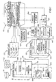
- Fig. 1 is a block diagram of an MRI system which employs the present invention;
- Fig. 2 is a graphic representation of a prior art FSE pulse sequence;
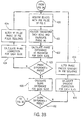
- Fig. 3 is a flow chart of the preferred embodiment of the prescan process of the present invention;
- Fig. 4 is a graphic representation of a modified FSE pulse sequence employed to compensate phase errors along the readout gradient axis;
- Fig. 5 is a graphic representation of another modified FSE pulse sequence employed to compensate phase errors along the phase-encoding gradient axis;
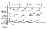
- Fig. 6 is a graphic representation of yet another modified FSE pulse sequence employed to compensate phase errors along the slice-selection gradient axis; and
- Fig. 7 is a graphic representation of the phase error measurements made with the pulse sequences of Figs. 4-6.
-
- Referring first to Fig. 1, there is shown the major components of a preferred MRI system which incorporates the present invention. The operation of the system is controlled from an
operator console 100 which includes a keyboard andcontrol panel 102 and adisplay 104. Theconsole 100 communicates through alink 116 with aseparate computer system 107 that enables an operator to control the production and display of images on thescreen 104. Thecomputer system 107 includes animage processor module 106, aCPU module 108 and amemory module 113. Thecomputer system 107 is linked to a disk storage 111 and atape drive 112 for storage of image data and programs, and it communicates with aseparate system control 122 through a high speedserial link 115. - The
system control 122 includes aCPU module 119 and apulse generator module 121 which connects to theoperator console 100 through aserial link 125. It is through thislink 125 that thesystem control 122 receives commands from the operator which indicate the scan sequence that is to be performed. In response to these commands thepulse generator module 121 produces data which indicate the timing, strength and shape of the RF excitation pulses, the timing and length of the data acquisition window, and it connects to a set ofgradient amplifiers 127, to control the timing and shape of the gradient pulses to be produced during the scan. Thepulse generator module 121 also receives patient data from aphysiological acquisition controller 129 that receives signals from a number of different sensors connected to the patient and it connects to a scan room interface circuit 133 which receives signals from various sensors associated with the condition of the patient and the magnet system. It is also through the scan room interface circuit 133 that apatient positioning system 134 receives commands to move the patient to the desired position for the scan. - The gradient waveforms produced by the
pulse generator module 121 are applied to agradient amplifier system 127 comprised of Gx, Gy and Gz amplifiers. Each gradient amplifier excites a corresponding gradient coil in an assembly generally designated 139 to produce the magnetic field gradients used for spatially encoding the acquired MR signals. Thegradient coil assembly 139 forms part of amagnet assembly 141 which also includes a polarizing magnet 140 and a whole-body RF coil 152. - A
transceiver module 150 in thesystem control 122 produces pulses which are amplified by anRF amplifier 151 and coupled to the RF coil 152 by a transmit/receiveswitch 154 to produce the RF excitation field B1. The MR signals radiated by the excited nuclei in the patient may be sensed by the same RF coil 152 and coupled through the transmit/receiveswitch 154 to apreamplifier 153. The transmit/receiveswitch 154 is controlled by a signal from thepulse generator module 121 to electrically connect theRF amplifier 151 to the coil 152 during the transmit mode and to connect thepreamplifier 153 during the receive mode. - The MR signals picked up by the RF coil 152 are filtered, demodulated using a reference signal, and digitized by the
transceiver module 150 and transferred to amemory module 160 throughbackplane 118 in thesystem control 122. When the scan is completed and an entire array of data has been acquired in thememory module 160, anarray processor 161 Fourier transforms the data into an array of image data. This image data is conveyed through theserial link 115 to thecomputer system 107 where it is stored in the disk memory 111. - Referring particularly to Fig. 2, the fast spin echo MR pulse sequence to be compensated is a 2DFT RARE sequence in which sixteen MR echo signals are acquired. For clarity, only four echo signals 301-304 are shown in Fig. 2, but it can be appreciated that twelve more are produced and acquired. These MR echo signals are produced by a 90

RF excitation pulse 305 which is generated in the presence of a Gz slice-select gradient pulse 306 to provide transverse magnetization in a slice through the patient. This transverse magnetization is refocused by each of sixteen selective 180RF refocusing pulses 307 and concurrent slice-select gradient pulses 300 to produce the MR spin echo signals 301-304 that are acquired in the presence of Gxreadout gradient pulses 308. Each MR spin echo signal 301-304 is separately phase encoded by respective Gy phase-encoding pulses 309-313. The magnitude of each phase-encoding pulse is different, and it is stepped through 256 values to acquire 256 separate views during a complete scan. Each MR spin echo signal is acquired by digitizing 256 samples of each signal and as a result, at the completion of a scan for one image, a 256 by 256 pixel image is produced by performing a 2D Fourier transformation on the acquired data. - The FSE pulse sequence of Fig. 2 uses a CPMG (Carr-Purcell-Meiboom-Gill) echo train to encode multiple views within a single echo train (or "shot"). These echo signals must be in phase if they are to correctly encode spatial information. Undesired phase shifts in the echo signals result in ghosting, blurring and signal loss in the reconstructed image. Such phase shifts may be spatially independent (i.e. zeroth order) or they may vary as a function of position (i.e. spatially first and higher order) from the system isocenter. One aspect of the present invention is that the zero order and first order phase errors along each of the three gradient axes can be measured during a prescan process, and the FSE pulse sequence may be modified, or compensated, to substantially eliminate image artifacts caused by these undesired phase shifts.
- The FSE scan of the preferred embodiment of the invention is performed under the direction of a program executed by the MR system of Fig. 1. As will be now described, in the preferred embodiment, a prescan is performed just prior to the FSE scan and includes the execution of a series of FSE pulse sequences which have been modified to collect the required corrective information. This corrective information is then used to alter the FSE pulse sequence employed during the scan to acquire MR data from which accurate images can be reconstructed. This procedure can also be used as an MRI system calibration process, in which case a separate prescan for each patient may not be required, or it may be greatly simplified.
- Referring particularly to Figs. 3A and 4, the first step in the prescan process is to execute the FSE pulse sequence of Fig. 4 as indicated at
process block 401. Thereadout gradients 308 and slice-select gradients echoes process block 402. The resulting "projection" at each slice location is an array of I and Q magnitude values at locations along the readout axis (x), and these are employed to calculate the phase of the echo signal at each location as follows:first echo signal 320 is illustrated, for example, by dashedline 403 in Fig. 7, and the phase values for thesecond echo signal 322 is illustrated bydotted line 404. Similar "phase profiles" are calculated for each slice of the scan. - Referring particularly to Figs. 3A and 7, the next step indicated by
process block 405 is to calculate the difference in phase (Δ0) between the twoecho signals 321 and 302 at the readout isocenter. If this phase difference Δ0 is less than a preset value (for example, 0.5decision block 406 and a phase correction calculation is made atprocess block 407. To correct the zeroth order phase error a correction equal to approximately one half the measured phase difference Δ0 is calculated, and this angle is added to the phase of each of the 180RF refocusing pulses 307 to alter their phase with respect to the 90RF excitation pulse 305. This alteration of the FSE pulse sequence is performed at process block 408 for each slice of the scan. - The procedure is then performed again with the altered FSE pulse sequence for each slice. The process repeats until the phase difference of each slice is within the preset value tested at
decision block 406. - Referring particularly to Figs. 3A and 7, the process continues at process block 410 to correct the FSE pulse sequence for each slice for first order phase shifts along the readout axis. More specifically, the slope (d1/dx) of the
phase profile 403 of thefirst echo signal 320 and the slope (d2/dx) of thephase profile 404 of thesecond echo signal 322 are calculated and the difference between these slopes (Δd/dx) is measured. As indicated atdecision block 411, if this difference exceeds a preset limit, the prescan loops back to further compensate the FSE pulse sequence for the slice. At process block 412 a correction to the readout gradient area is calculated by dividing the slope difference Δd/dx by the gyromagnetic constant γ (i.e. 4257 Hz/gauss). As indicated atprocess block 413, this calculated gradient area adjustment is added to the readout gradient dephaser pulse 414 (Fig. 2) in the FSE pulse sequence of Fig. 4 to form a readoutgradient compensation pulse 324. The prescan is then repeated and thereadout gradient pulse 324 adjusted until the slope difference Δd/dx for each slice is reduced below the preset level tested atdecision block 411. - In the next part of the prescan procedure, the phase error along the phase-encoding axis in the FSE pulse sequence is measured and compensated. Referring particularly to Fig. 3B, this is accomplished using the FSE pulse sequence of Fig. 5 as indicated at
process block 420. This pulse sequence is the same as that in Fig. 2 in many respects such as theRF pulses select gradient pulses readout gradient pulses 308 anddephaser pulse 324 are turned off. This is indicated in Fig. 5 by the acquisition of the two central-most k-space echo signals 320 and 322 withoutreadout gradient pulses 308. In the phase-encoding direction, the regular phase-encoding gradient pulses (e.g. 309 and 310) are played out in the usual manner throughout the FSE shot, except during the acquisition of the twoecho signals gradient pulses like gradient pulses gradient pulses - Referring particularly to Figs. 3B and 7, as was done above, both acquired echo signals 320 and 322 are Fourier transformed along the phase-encoding axis at
process block 421 and the phase profiles 403 and 404 are calculated. The phase difference (Δ0) at the y-axis isocenter is again determined from the twophase profiles process block 422, and corrections are made if it exceeds a preset amount as determined atdecision block 423. If adjustment is needed, a phase correction is calculated at 424 which is substantially one-half the measured phase difference (Δ0/2) and it is applied at process block 425 to shift the phase of the 90RF excitation pulse 305 relative to theRF refocusing pulses 307. This phase adjustment is made to each of the sixteen shots for each slice of the scan until all the corresponding FSE pulse sequences produce a phase difference within the preset limit tested atdecision block 423. - Referring still to Figs. 3B and 7, the next step is to compensate the FSE pulse sequence for each slice for first order phase shifts along the phase-encoding gradient axis (y in the preferred embodiment). As indicated at
process block 430, the slope (d1/dy) of thephase profile 403 of thefirst echo signal 320 and the slope (d2/dy) of thephase profile 404 of thesecond echo signal 322 are calculated and the difference between these slopes (Δd/dy) is measured. As indicated atdecision block 432, if this difference exceeds a preset limit, the process loops back to further compensate the FSE pulse sequence for the slice. At process block 434 a correction to the phase-encoding gradient is calculated by dividing the slope difference Δd/dy by the gyromagnetic constant γ to produce a phase-encoding gradient area correction value. As indicated atprocess block 436, this calculated gradient area adjustment is added to the FSE pulse sequence phase-encoding gradient pulse 340 which is applied after theRF excitation pulse 305 and prior to the firstRF refocusing pulse 307. The compensation process is repeated and the phase-encoding compensation pulse 340 adjusted until the slope difference Δd/dy for each slice is reduced below the preset level tested atdecision block 432. - In the third phase of the procedure the phase error along the slice-selection axis due to gradients along all three gradient axes is compensated. Referring particularly to Fig. 3C, this is accomplished as indicated by
process block 440 using the pulse sequence in Fig. 6. This pulse sequence employs thesame rf pulses readout gradient pulses 308 are the same as in the FSE pulse sequence, but the dephasing gradient pulse 414 is replaced with the readoutgradient compensation pulse 324. The normal phase-encoding pulses (e.g. 309 and 310) are applied prior to each echo signal acquisition in the shot, but the phase-encoding is set to zero during acquisition of the twoecho signals compensation gradient pulse 340 calculated in previous steps is applied to minimize phase errors along the phase-encoding axis and the usual slice-select gradient pulses - The acquired echo signals 320 and 322 are Fourier transformed as indicated at
process block 422 and the integral of either transformed signal is calculated at process block 444 to measure its area. A test is made atdecision block 446 to determine if this integral has reached its maximum possible value, and if not, a slice-select compensation pulse 350 is incremented in value as indicated atprocess block 448. The modified pulse sequence of Fig. 6 is then used to reacquire the twoecho signals compensation gradient pulse 350 is optimal, and then the integral will begin to drop in value. When the maximum integral value is detected atdecision block 446, the calibration is complete and the system exits at 450. By maximizing the integral of the central k-space echo in this manner, the first order phase errors along the slice-select gradient axis are compensated. - This completes the FSE compensation process. The phase shifts and the
compensation gradient pulses - One logical variation in the preferred method described above is to carry out the phase correction along the phase encode and slice-select axes first and do the phase correction along the readout axis as the last step. This variation has the advantage in that the zeroth order phase error is determined using a pulse sequence closely resembling the actual imaging sequence.
- Also, in the preferred embodiment the zeroth order phase errors are measured twice, once when measuring phase errors along the phase-encoding gradient axis and once when measuring phase errors along the readout gradient axis. The zeroth order phase shift corrections can be calculated from both measurements or from only one of the measurements. Since the choice does not change total scan time, using both measurements is preferred.
- It should be noted that many variations exist in calculating the zeroth and first order phase differences between the two echoes in the central k-space. Although we have described one simple approach to calculate the phase difference (i.e., obtaining the zeroth and first order phases for individual echoes first then take the difference), an alternative way is to first take the phase difference from the complex echo signals then obtain the zeroth and first order phases from the phase difference. This latter approach is more immune to the phase-wrap problems. Of course, the phase difference can also be obtained using the algorithm proposed by Ahn and Cho, "A New Phase Correction Method in NMR Imaging Based on Autocorrection and Histogram Analysis", IEEE Transactions on Medical Imaging. Vol. MI-6, No. I, March 1987.
Claims (10)
- A prescan for a magnetic resonance imaging system which performs a scan to acquire MR data using a fast spin echo (FSE) pulse sequence in which an RF magnetic field is produced by an RF excitation pulse followed by a series of RF refocusing pulses and readout, phase-encoding and slice-select magnetic field gradients are applied to spatially encode echo signals that are acquired during the pulse sequence, the prescan, in which the FSE pulse sequence is adjusted prior to conducting the scan, comprising:a) acquiring MR data using a first modified FSE pulse sequence;b) calculating first order phase error that corresponds to readout gradient corrections from the MR data acquired in step a);c) acquiring MR data using a second modified FSE pulse sequence;d) calculating first order phase error that corresponds to phase-encoding gradient corrections from the MR data acquired in step c)e) calculating zeroth order phase error that corresponds to spatially invariant magnetic field corrections from the MR data acquired in step a) or step c);f) acquiring MR data using a third modified FSE pulse sequence;g) calculating a first order phase error that corresponds to slice-select gradient correction from the MR data acquired in step f); andh) adjusting the FSE pulse sequence with the phase shift corrections calculated in steps b), d), e) and g).
- The prescan method as recited in claim 1 in which the second modified FSE pulse sequence used in step c) includes phase shift corrections calculated in step b).
- The prescan sequence as recited in claim 1 or 2 in which the third modified FSE pulse sequence used in step f) includes phase shift corrections calculated in step d).
- The prescan method as recited in claim 1, 2 or 3 in which the adjustment made to the FSE pulse sequence in step h) includes adding a readout gradient compensation pulse after the RF excitation pulse and prior to the series of RF refocusing pulses.
- The prescan method as recited in any preceding claim in which the adjustment made to the FSE pulse sequence in step h) includes adding a phase-encoding gradient compensation pulse after the RF excitation pulse and prior to the series of RF refocusing pulses.
- The prescan method as recited in any preceding claim in which the adjustment made to the FSE pulse sequence in step h) includes adding a slice-select gradient compensation pulse after the RF excitation pulse and prior to the series of RF refocusing pulses.
- An MR system which comprisesa first means for performing a first modified FSE pulse sequence to measure first order phase errors along a readout gradient axis;second means for performing a second modified FSE pulse sequence to measure first order phase errors along a phase-encoding gradient axis;third means for performing a third modified FSE pulse sequence to measure first order phase errors along a slice-select gradient axis; andfourth means for compensating an FSE pulse sequence used to perform an imaging scan using the first order phase errors measured by the first, second and third means.
- The MR system as recited in claim 7 in which the fourth means includes:means for altering the relative phase of RF pulses produced by the MR system when performing said FSE pulse sequence; andmeans for adding compensation gradient pulses that are produced by the MR system when performing said FSE pulse sequence.
- The MR system as recited in claim 7 or 8 in which the first, second and third means include:means for producing an RF excitation pulse and a series of RF refocusing pulses;means for producing phase-encoding gradient pulses;means for producing slice-select gradient pulses when said RF excitation pulse and each of the RF refocusing pulses are produced;means for producing a readout gradient pulse; andmeans for acquiring NMR signals produced after each RF refocusing pulse.
- The MR system as recited in claim 7, 8 or 9 in which the first, second and third means each include means for acquiring NMR signals that sample a central region of k-space.
Applications Claiming Priority (2)
| Application Number | Priority Date | Filing Date | Title |
|---|---|---|---|
| US325081 | 1999-06-03 | ||
| US09/325,081 US6369568B1 (en) | 1999-06-03 | 1999-06-03 | Fast spin echo phase correction for MRI system |
Publications (1)
| Publication Number | Publication Date |
|---|---|
| EP1058123A1 true EP1058123A1 (en) | 2000-12-06 |
Family
ID=23266354
Family Applications (1)
| Application Number | Title | Priority Date | Filing Date |
|---|---|---|---|
| EP00304618A Ceased EP1058123A1 (en) | 1999-06-03 | 2000-05-31 | Fast spin echo phase correction for MRI system |
Country Status (3)
| Country | Link |
|---|---|
| US (1) | US6369568B1 (en) |
| EP (1) | EP1058123A1 (en) |
| JP (1) | JP4693209B2 (en) |
Cited By (4)
| Publication number | Priority date | Publication date | Assignee | Title |
|---|---|---|---|---|
| DE10063676A1 (en) * | 2000-12-20 | 2002-07-04 | Siemens Ag | Nuclear magnetic resonance imaging method for medical purposes uses compensation phase coding gradient pulse to reduce image artifacts without increasing measurement time |
| WO2003098548A2 (en) * | 2002-05-15 | 2003-11-27 | Case Western Reserve University | Method to correct magnetic field/phase variations in proton resonance frequency shift thermometry in magnetic resonance imaging |
| CN102258370A (en) * | 2010-05-31 | 2011-11-30 | 株式会社东芝 | Magnetic resonance imaging apparatus |
| CN115685032A (en) * | 2022-11-02 | 2023-02-03 | 佛山瑞加图医疗科技有限公司 | Method and system for correcting fast spin echo under spoke k space |
Families Citing this family (35)
| Publication number | Priority date | Publication date | Assignee | Title |
|---|---|---|---|---|
| JPS6359135A (en) * | 1986-08-29 | 1988-03-15 | Canon Inc | Communication equipment |
| JP2577395B2 (en) * | 1987-08-12 | 1997-01-29 | 日本電信電話株式会社 | Cordless telephone equipment |
| US6853188B2 (en) * | 1999-12-31 | 2005-02-08 | Advanced Mri Technologies, Llc | Method and apparatus for removing specific stimulated echoes in simultaneous image refocusing |
| DE10038669C1 (en) * | 2000-08-08 | 2002-01-31 | Siemens Ag | Operating magnetic resonance device involves using movement model describing translation movements of at least defined points of image area with time dependency during acquisition |
| JP3875479B2 (en) * | 2000-10-20 | 2007-01-31 | ジーイー・メディカル・システムズ・グローバル・テクノロジー・カンパニー・エルエルシー | Magnetic resonance imaging device |
| US6803763B2 (en) * | 2003-01-13 | 2004-10-12 | Ge Medicalsystems Technology Company, Llc | Method and system for retrospective phase correction for fast spin echo magnetic resonance imaging |
| US7141972B2 (en) * | 2003-11-17 | 2006-11-28 | Toshiba America Mri, Inc. | Water-fat separation for fast spin echo imaging in an inhomogeneous field with progressive encoding |
| JP4619674B2 (en) * | 2004-03-24 | 2011-01-26 | 株式会社東芝 | Magnetic resonance imaging system |
| US7187171B2 (en) * | 2005-02-10 | 2007-03-06 | Kaburhiki Kaisha Toshiba | Magnetic resonance imaging apparatus and its control method |
| US7689263B1 (en) * | 2005-09-15 | 2010-03-30 | General Electric Company | Method and apparatus for acquiring free-breathing MR images using navigator echo with saturation RF pulse |
| US7239137B2 (en) * | 2005-09-20 | 2007-07-03 | General Electric Company | Method and apparatus for fast spin echo (FSE) prescan phase correction |
| DE102006006274B3 (en) * | 2006-02-10 | 2007-09-27 | Siemens Ag | Picture artifacts correcting method, involves determining phase error condition corresponding to correction field pulse, which generates phase correction, per gradient coil, and determining constant phase for phase correction |
| US8115485B1 (en) * | 2006-03-10 | 2012-02-14 | General Electric Company | Method and apparatus for interactively setting parameters of an MR imaging sequence through inspection of frequency spectrum |
| US7298146B1 (en) * | 2006-06-23 | 2007-11-20 | General Electric Compnay | Method and apparatus of manual pre-scan spatial and spectral data acquisition |
| JP4249215B2 (en) * | 2006-10-06 | 2009-04-02 | ジーイー・メディカル・システムズ・グローバル・テクノロジー・カンパニー・エルエルシー | Magnetic resonance imaging system |
| JP5570713B2 (en) | 2007-09-27 | 2014-08-13 | 株式会社東芝 | Magnetic resonance imaging system |
| JP2009254583A (en) * | 2008-04-16 | 2009-11-05 | Toshiba Corp | Magnetic resonance imaging apparatus and controlling method therefor |
| JP5422194B2 (en) * | 2008-12-18 | 2014-02-19 | 株式会社東芝 | Magnetic resonance imaging system |
| US8653816B2 (en) * | 2009-11-04 | 2014-02-18 | International Business Machines Corporation | Physical motion information capturing of a subject during magnetic resonce imaging automatically motion corrected by the magnetic resonance system |
| JP5686660B2 (en) * | 2010-05-27 | 2015-03-18 | 株式会社東芝 | Magnetic resonance imaging apparatus and method |
| JP5925529B2 (en) * | 2011-03-31 | 2016-05-25 | 株式会社東芝 | Magnetic resonance imaging system |
| JP6194032B2 (en) * | 2011-03-31 | 2017-09-06 | 東芝メディカルシステムズ株式会社 | Magnetic resonance imaging system |
| JP6084392B2 (en) | 2011-09-22 | 2017-02-22 | 東芝メディカルシステムズ株式会社 | Magnetic resonance imaging system |
| DE102011083395B4 (en) * | 2011-09-26 | 2013-06-13 | Siemens Aktiengesellschaft | Correction of distortions in MR images due to inhomogeneities of the basic magnetic field |
| JP6139119B2 (en) | 2012-01-13 | 2017-05-31 | 東芝メディカルシステムズ株式会社 | Magnetic resonance imaging system |
| WO2014030621A1 (en) * | 2012-08-22 | 2014-02-27 | 株式会社 日立メディコ | Magnetic resonance imaging apparatus and method |
| WO2014164963A1 (en) * | 2013-03-12 | 2014-10-09 | Levin Pavel | Method and apparatus for magnetic resonance imaging |
| US10274569B2 (en) * | 2013-03-29 | 2019-04-30 | Koninklijke Philips N.V. | Magnetic resonance imaging system with ghost artifact reduction and method operation thereof |
| DE102014206929B4 (en) * | 2014-04-10 | 2015-10-29 | Siemens Aktiengesellschaft | Suppression of unwanted coherence paths in MR imaging |
| JP6495057B2 (en) | 2015-03-16 | 2019-04-03 | キヤノンメディカルシステムズ株式会社 | MRI apparatus and imaging time reduction method |
| US10712420B2 (en) * | 2015-05-29 | 2020-07-14 | Mayo Foundation For Medical Education And Research | Systems and methods for concomitant field correction in magnetic resonance imaging with asymmetric gradients |
| JP6591208B2 (en) * | 2015-06-09 | 2019-10-16 | キヤノンメディカルシステムズ株式会社 | Magnetic resonance imaging system |
| WO2017012436A1 (en) | 2015-07-23 | 2017-01-26 | Shanghai United Imaging Healthcare Co., Ltd. | System and method for magnetic resonance imaging |
| EP3693752B1 (en) | 2019-02-05 | 2023-03-29 | Siemens Healthcare GmbH | Method for operating an mri device, corresponding mri device, computer program product, and computer-readable storage medium |
| US11085988B2 (en) | 2019-03-20 | 2021-08-10 | The Board Of Trustees Of The Leland Stanford Junior University | Method for estimating systematic imperfections in medical imaging systems with deep learning |
Citations (4)
| Publication number | Priority date | Publication date | Assignee | Title |
|---|---|---|---|---|
| US5378985A (en) * | 1993-07-15 | 1995-01-03 | General Electric Company | Fast spin echo prescan for MRI system |
| EP0818689A1 (en) * | 1996-07-11 | 1998-01-14 | Ge Yokogawa Medical Systems, Ltd. | MRI method of phase shift measurement, MRI method of phase shift correction, and MRI apparatus carrying out these methods |
| EP0845684A1 (en) * | 1996-11-27 | 1998-06-03 | Picker International, Inc. | Phase Correction in Multiple-Echo Magnetic Resonance Imaging |
| US5818229A (en) * | 1995-10-31 | 1998-10-06 | Kabushiki Kaisha Toshiba | Correction of MR imaging pulse sequence using prescan having application phase adjusted RF refocusing pulses |
Family Cites Families (3)
| Publication number | Priority date | Publication date | Assignee | Title |
|---|---|---|---|---|
| US4698591A (en) | 1986-01-03 | 1987-10-06 | General Electric Company | Method for magnetic field gradient eddy current compensation |
| US6160397A (en) * | 1998-12-30 | 2000-12-12 | General Electric Company | Fast spin echo prescan for magnetic resonance imaging systems |
| JP3585899B2 (en) * | 2002-05-13 | 2004-11-04 | 株式会社東芝 | Magnetic resonance imaging |
-
1999
- 1999-06-03 US US09/325,081 patent/US6369568B1/en not_active Expired - Fee Related
-
2000
- 2000-05-31 EP EP00304618A patent/EP1058123A1/en not_active Ceased
- 2000-06-01 JP JP2000163930A patent/JP4693209B2/en not_active Expired - Fee Related
Patent Citations (4)
| Publication number | Priority date | Publication date | Assignee | Title |
|---|---|---|---|---|
| US5378985A (en) * | 1993-07-15 | 1995-01-03 | General Electric Company | Fast spin echo prescan for MRI system |
| US5818229A (en) * | 1995-10-31 | 1998-10-06 | Kabushiki Kaisha Toshiba | Correction of MR imaging pulse sequence using prescan having application phase adjusted RF refocusing pulses |
| EP0818689A1 (en) * | 1996-07-11 | 1998-01-14 | Ge Yokogawa Medical Systems, Ltd. | MRI method of phase shift measurement, MRI method of phase shift correction, and MRI apparatus carrying out these methods |
| EP0845684A1 (en) * | 1996-11-27 | 1998-06-03 | Picker International, Inc. | Phase Correction in Multiple-Echo Magnetic Resonance Imaging |
Non-Patent Citations (2)
| Title |
|---|
| JUWHAN LIU ET AL: "AN AUTOMATIC PHASE CORRECTION METHOD IN NUCLEAR MAGNETIC RESONANCE IMAGING", JOURNAL OF MAGNETIC RESONANCE,US,ACADEMIC PRESS, ORLANDO, FL, vol. 86, no. 3, 15 February 1990 (1990-02-15), pages 593 - 604, XP000132485, ISSN: 1090-7807 * |
| XIAOHONG ZHOU ET AL: "ON PHASE ARTIFACTS OF HIGH-FIELD FAST SPIN-ECHO IMAGES", MEETING AND EXHIBITION OF THE SOCIETY OF MAGNETIC RESONANCE IN MEDICINE,US,BERKELEY, SMRM, vol. MEETING 12, 14 August 1993 (1993-08-14), pages 1248, XP002024481, ISSN: 1065-9889 * |
Cited By (10)
| Publication number | Priority date | Publication date | Assignee | Title |
|---|---|---|---|---|
| DE10063676A1 (en) * | 2000-12-20 | 2002-07-04 | Siemens Ag | Nuclear magnetic resonance imaging method for medical purposes uses compensation phase coding gradient pulse to reduce image artifacts without increasing measurement time |
| US6667617B2 (en) | 2000-12-20 | 2003-12-23 | Siemens Aktiengesellschaft | Multi-echo magnetic resonance imaging method with reduction of artifacts caused by remanence magnetization |
| DE10063676B4 (en) * | 2000-12-20 | 2006-08-17 | Siemens Ag | Multi-echo imaging method |
| WO2003098548A2 (en) * | 2002-05-15 | 2003-11-27 | Case Western Reserve University | Method to correct magnetic field/phase variations in proton resonance frequency shift thermometry in magnetic resonance imaging |
| WO2003098548A3 (en) * | 2002-05-15 | 2004-10-28 | Univ Case Western Reserve | Method to correct magnetic field/phase variations in proton resonance frequency shift thermometry in magnetic resonance imaging |
| US7359745B2 (en) | 2002-05-15 | 2008-04-15 | Case Western Reserve University | Method to correct magnetic field/phase variations in proton resonance frequency shift thermometry in magnetic resonance imaging |
| CN102258370A (en) * | 2010-05-31 | 2011-11-30 | 株式会社东芝 | Magnetic resonance imaging apparatus |
| CN102258370B (en) * | 2010-05-31 | 2013-08-07 | 株式会社东芝 | Magnetic resonance imaging apparatus |
| US9041394B2 (en) | 2010-05-31 | 2015-05-26 | Kabushiki Kaisha Toshiba | Magnetic resonance imaging apparatus executing phase-corrected imaging pulse sequence based on data obtained from multiple pulse sub-sequences executed without readout direction gradients but instead using phase or slice encoding direction gradients during readout |
| CN115685032A (en) * | 2022-11-02 | 2023-02-03 | 佛山瑞加图医疗科技有限公司 | Method and system for correcting fast spin echo under spoke k space |
Also Published As
| Publication number | Publication date |
|---|---|
| JP2001025463A (en) | 2001-01-30 |
| US6369568B1 (en) | 2002-04-09 |
| JP4693209B2 (en) | 2011-06-01 |
Similar Documents
| Publication | Publication Date | Title |
|---|---|---|
| US6369568B1 (en) | Fast spin echo phase correction for MRI system | |
| US5378985A (en) | Fast spin echo prescan for MRI system | |
| US7495439B2 (en) | MRI method for reducing artifacts using RF pulse at offset frequency | |
| US6078176A (en) | Fast spin echo pulse sequence for diffusion weighted imaging | |
| US5770943A (en) | Method for measuring and compensating for spatially and temporally varying magnetic fields induced by eddy currents | |
| US5151656A (en) | Correction of nmr data acquired by an echo-planar technique | |
| US6064205A (en) | Correction of artifacts caused by maxwell terms in slice offset echo planar imaging | |
| US6559642B2 (en) | Calibration method for use with sensitivity encoding MRI acquisition | |
| US5001428A (en) | Method for mapping the RF transmit and receive field in an NMR system | |
| US8482279B2 (en) | System and method of parallel imaging for magnetic resonance imaging near metallic implants | |
| EP1636604B1 (en) | Isotropic imaging of vessels with fat suppression | |
| EP1037067A1 (en) | Non-CPMG fast spin echo MRI method | |
| EP1139114A2 (en) | Slice ordering method for breath-hold abdominal MR imaging | |
| US7197353B2 (en) | Sensitivity encoding MRI acquisition method | |
| US6111411A (en) | RF power calibration for an MRI system using multiple axis projections | |
| US6469505B1 (en) | Method and apparatus to reduce perturbation field effects in MR images by restricting the region of interest | |
| US4968935A (en) | Selective rephasing of NMR signals to suppress motion artifacts | |
| EP1372110B1 (en) | Method and system for image reconstruction | |
| US5917323A (en) | Correction of axial image signal fall off caused by Maxwell terms | |
| EP1102082A2 (en) | Method and apparatus for reducing image artifacts caused by magnet vibration in an MR imaging system | |
| US6157192A (en) | Recovery of signal void arising from field inhomogeneities in echo planar imaging | |
| US6025718A (en) | RF power calibration for an MRI system using local coils | |
| US6239597B1 (en) | Method and apparatus for rapid T2 weighted MR image acquisition | |
| US20220057467A1 (en) | Epi mr imaging with distortion correction | |
| WO2018001759A1 (en) | Diffusion weighted mr imaging using multi-shot epi with motion detection and modified sense reconstruction |
Legal Events
| Date | Code | Title | Description |
|---|---|---|---|
| PUAI | Public reference made under article 153(3) epc to a published international application that has entered the european phase |
Free format text: ORIGINAL CODE: 0009012 |
|
| AK | Designated contracting states |
Kind code of ref document: A1 Designated state(s): DE NL |
|
| AX | Request for extension of the european patent |
Free format text: AL;LT;LV;MK;RO;SI |
|
| 17P | Request for examination filed |
Effective date: 20010606 |
|
| AKX | Designation fees paid |
Free format text: DE NL |
|
| 17Q | First examination report despatched |
Effective date: 20031223 |
|
| APBN | Date of receipt of notice of appeal recorded |
Free format text: ORIGINAL CODE: EPIDOSNNOA2E |
|
| APBR | Date of receipt of statement of grounds of appeal recorded |
Free format text: ORIGINAL CODE: EPIDOSNNOA3E |
|
| APAF | Appeal reference modified |
Free format text: ORIGINAL CODE: EPIDOSCREFNE |
|
| APBT | Appeal procedure closed |
Free format text: ORIGINAL CODE: EPIDOSNNOA9E |
|
| 18R | Application refused |
Effective date: 20070714 |
|
| R18R | Application refused (corrected) |
Effective date: 20070523 |
|
| STAA | Information on the status of an ep patent application or granted ep patent |
Free format text: STATUS: THE APPLICATION HAS BEEN REFUSED |
|
| R18R | Application refused (corrected) |
Effective date: 20070714 |