EP1058087B1 - Position recording of an edge with distributed sensors by determining the turning point - Google Patents
Position recording of an edge with distributed sensors by determining the turning point Download PDFInfo
- Publication number
- EP1058087B1 EP1058087B1 EP00110943A EP00110943A EP1058087B1 EP 1058087 B1 EP1058087 B1 EP 1058087B1 EP 00110943 A EP00110943 A EP 00110943A EP 00110943 A EP00110943 A EP 00110943A EP 1058087 B1 EP1058087 B1 EP 1058087B1
- Authority
- EP
- European Patent Office
- Prior art keywords
- sensors
- web
- sensor
- point
- inflection
- Prior art date
- Legal status (The legal status is an assumption and is not a legal conclusion. Google has not performed a legal analysis and makes no representation as to the accuracy of the status listed.)
- Expired - Lifetime
Links
Images

Classifications
-
- G—PHYSICS
- G01—MEASURING; TESTING
- G01B—MEASURING LENGTH, THICKNESS OR SIMILAR LINEAR DIMENSIONS; MEASURING ANGLES; MEASURING AREAS; MEASURING IRREGULARITIES OF SURFACES OR CONTOURS
- G01B11/00—Measuring arrangements characterised by the use of optical techniques
- G01B11/02—Measuring arrangements characterised by the use of optical techniques for measuring length, width or thickness
- G01B11/028—Measuring arrangements characterised by the use of optical techniques for measuring length, width or thickness by measuring lateral position of a boundary of the object
-
- B—PERFORMING OPERATIONS; TRANSPORTING
- B65—CONVEYING; PACKING; STORING; HANDLING THIN OR FILAMENTARY MATERIAL
- B65H—HANDLING THIN OR FILAMENTARY MATERIAL, e.g. SHEETS, WEBS, CABLES
- B65H23/00—Registering, tensioning, smoothing or guiding webs
- B65H23/02—Registering, tensioning, smoothing or guiding webs transversely
- B65H23/0204—Sensing transverse register of web
-
- B—PERFORMING OPERATIONS; TRANSPORTING
- B65—CONVEYING; PACKING; STORING; HANDLING THIN OR FILAMENTARY MATERIAL
- B65H—HANDLING THIN OR FILAMENTARY MATERIAL, e.g. SHEETS, WEBS, CABLES
- B65H2553/00—Sensing or detecting means
- B65H2553/10—Sensing or detecting means using fluids, e.g. pneumatics
-
- B—PERFORMING OPERATIONS; TRANSPORTING
- B65—CONVEYING; PACKING; STORING; HANDLING THIN OR FILAMENTARY MATERIAL
- B65H—HANDLING THIN OR FILAMENTARY MATERIAL, e.g. SHEETS, WEBS, CABLES
- B65H2553/00—Sensing or detecting means
- B65H2553/30—Sensing or detecting means using acoustic or ultrasonic elements
-
- B—PERFORMING OPERATIONS; TRANSPORTING
- B65—CONVEYING; PACKING; STORING; HANDLING THIN OR FILAMENTARY MATERIAL
- B65H—HANDLING THIN OR FILAMENTARY MATERIAL, e.g. SHEETS, WEBS, CABLES
- B65H2553/00—Sensing or detecting means
- B65H2553/40—Sensing or detecting means using optical, e.g. photographic, elements
Definitions
- the invention relates to a method for detecting the position a running web according to the preamble of Claim 1 and a device for performing this method according to the preamble of the claim 9.
- DE 34 23 308 C2 describes a photoelectronic sensing device known, in which one light source several, opposite to each other acting receiver parts.
- the receiver parts are made of semiconductor photo elements formed optically on light-collecting Plastic surfaces are coupled.
- Each of these receiver parts covers a specific area of the web, wherein the photo element is a for covering by the web proportional signal.
- the web edge position is by comparing that of the photo elements emitted signals determined with a threshold.
- this Sensing device achievable resolution essentially of Corresponds to the width of the plastic plates. To achieve a high resolution with a large measuring range therefore a very large number of photo elements is required. In addition, in this case there is a very large number of photo elements to be queried in every measuring cycle.
- DE 42 09 546 C2 describes a device for determining the position of the edge of a running material web is known, with the multiple, separately controllable light sources one receiver part is opposite each other.
- This Receiver parts give a proportional to the coverage of the web Signal from that compared to a threshold becomes.
- the comparison result is a microcomputer fed, depending on the comparison result the light sources and receiver parts according to one successive approximation and in this way the position of the web edge is determined.
- To carry out the successive approximation must be a number of Comparison values of the receiver parts with the threshold value stored in a memory unit of the microcomputer become.
- the invention has for its object a method of the type mentioned at the outset to create a high Resolution achieved with a short measuring time.
- a inexpensive device for performing this method be created.
- Each sensor generates a signal that depending on the coverage of the sensor by the web is.
- the signal generated by the sensor is preferably proportional to the coverage by the web.
- each sensor delivers a position of the web edge dependent signal, with the individual sensors in different Areas are arranged in the measuring direction.
- the web is preferably scanned without contact, not even sensitive webs damaged by the sensors. It will also be on this prevents the sensors themselves from edge detection disturb, like this for example with a mechanical edge sensor is the case with spring force presses against the web edge.
- the web edge are those viewed from the center of the web inner sensors completely through the web covered, so that these sensors have a constant idle signal submit.
- the outer sensors are opposite not covered by the web in any way, making it a generate maximum signal.
- the sensors in the area around the Web edge provide signals between the idle signal and the maximum signal.
- the function of signals generated by the sensors from the sensor locations therefore two constant areas with approximately medium edge position different signal levels between which one continuous transition area is provided.
- At extreme Position of the web edge in the area of the innermost or outermost Sensor can be one of the constant ranges too are missing, so that edge determination via threshold values in this case becomes very inaccurate.
- the individual are preferred Sensors equidistant across the web direction distributed so that the sensor location is particularly easy can be determined by numbering the sensors.
- the sensor signals are determined by the sensor number, being the result of the turning point search in this Multiply the case by the mutual distance of the sensors is.
- the turning point can also be from a Function of the sensor signals of values belonging to the Sensor locations are proportional, can be determined. To one to get correctly scaled web edge position, the determined inflection point with the proportionality factor be multiplied. In those cases where only a signal proportional to the edge position is needed, for example in web guiding devices the case may be on a corresponding one Correction of the determined turning point also waived become.
- the sensor is integrated his signal from a given area, so that small area Deposits on the sensor surface are only minimal Have an influence on the signal generated by the sensor. This is particularly the case with heavily linting webs important, because lint originating directly from the web of goods can deposit on the sensor surface. If they had Sensors an effective width below about 1 mm, so every single lint could have full coverage of a sensor cause what is mistakenly called the web edge would be interpreted. Thanks to the extensive training The effective sensor surface can only be deposited lint for an even attenuation of the signals of all Sensors lead, however, to the location of the turning point has no influence. With this measure increased sensitivity to dirt of the edge sensing device reached. Because the turning point is much more accurate can be determined as the distance of the individual sensors, this measure does not affect accuracy the edge determination.
- the detection methods proposed in claim 3 the web cover work without contact and disturb therefore in no way the web run. You can also click on this way, especially sensitive webs are safe be detected without the risk of damage the web or a measurement falsification.
- An optical detection of the web cover takes place either in the reflection process or in the light barrier principle.
- the web of at least illuminated by a light source being light sensitive Receiver either on the opposite of the web Side or next to the light source are provided.
- the web cover could also be on pneumatic Paths can be scanned using air jets, whereby in this case, provide pressure-sensitive sensors are. With an acoustic scanning of the web Sound waves directed against the web by Microphones can be detected.
- a particularly simple and therefore interference-free detection of the inflection point follows from claim 4 the function of the signals from the sensor location twice numerically differentiated and one from the second derivative function Zero determined.
- the one corresponding to the edge position Zero of the second derivative is in the range the greatest slope, i.e. at a maximum value the first derivative. From these conditions, the Edge position determined with little computing effort become.
- the turning point according to claim 5 can also by simple numerical differentiation and numerical Find the maximum of the first derivative function be determined. In this way there is a second differentiation saved, however, the search of the maximum the first derivative function is numerically more complex is.
- this method has the advantage that the condition to search for the absolute maximum without any additional constraint the position of the web edge provides.
- the The turning point is calculated directly from the fit parameters becomes.
- the approximation of the fit function to the signals of the Sensors are preferably made using the minimization method the squares of the deviations of the signals from the corresponding function values of the fit function.
- the turning point can generally be done analytically by two Differentiate and zero the fit function be, so that depending on the fit function a more or less simple formula for calculating the turning point from the Fit parameters can be specified.
- a fit function according to claim 7 Polynomial used, whose coefficients are the fit parameters are. From this polynomial the second one can be very easily Calculate the derivative analytically, so that from the polynomial coefficients the turning point can be determined directly can.
- the signals of the individual are proposed Sensors by the signal of a reference sensor to divide.
- This measure can measuring errors for example, from a changing illuminance originate from the transmitter, be eliminated. Will the Signals from the sensor and the reference sensor are recorded promptly, this can also cause short-term fluctuations in the transmitter be balanced.
- a sensor is preferably used in each case alternately queried with the reference sensor to determine transmitter fluctuations balance as optimally as possible.
- the device according to claim 9 has been implemented of the method according to the invention particularly proven.
- This device has several sensors, each generate a signal dependent on the coverage of the web. These sensors are preferably transverse to the web running direction placed in a row next to each other. Alternatively, you could they also zigzag staggered his. It is important that the individual sensors from one fixed imaginary web edge different distances exhibit. This ensures that each sensor in one certain width range on changes in web edge responds. However, if the sensor is completely removed from the Path covered, it only generates a rest signal. If the sensor is not covered by the web at all, so it generates a maximum active signal.
- the single ones Sensors are via switching means with an analog-to-digital converter connected.
- This switching means that the signals from each sensor are sequential queried and converted into a digital value can.
- These switching means are available with storage means in Active connection in which the digitized values are stored become.
- a turning point detector can be placed on these storage means access that from the function of digitized Values from the sensor locations a turning point determined.
- the digital value calculated by the inflection point detector is output at a digital output and stands thus other devices such as web edge regulators or Display instruments available.
- the senor as a photodetector with assigned plate made of light-collecting plastic to train.
- a fluorescent in the plastic plate Contain substance that is from the light source converts incoming light into longer wave light that spreads preferentially in the plate plane.
- the photo detector is coupled to the front of the plate, so that he is a very strong and therefore insensitive to interference Light signal receives. Due to the occurrence of total reflections the light is distributed on the plate surfaces Light evenly over the entire plate so that the Sensor is exactly proportional to the coverage by the web Signal delivers. It doesn't matter whether the light is evenly distributed or only on a certain one Spot penetrates the plastic plate.
- this element is a body with a Variety of perpendicular to the web Surfaces.
- the element of pipe pieces, parallel walls or a honeycomb structure be educated.
- the item could be from a Row of lenses or a bundle of glass or plastic fibers be educated. It is only important that the Light rays, seen in the direction of detection of the device, are aligned parallel to each other. In the direction of the web seen, however, play different Beam directions of light only a subordinate Role.
- a particularly simple implementation of the switching means for time-delayed query of the sensors results from Claim 12 in the form of an analog multiplexer.
- An analog multiplexer is available as an integrated circuit and thus insensitive to chemicals and elevated Temperatures, such as when processing textiles Material webs occur. So that the generated by the sensors Signals through the non-negligible on-resistance of the analog multiplexer are not falsified, the signals are not considered as voltage but as Transfer current values.
- a subsequent analog-to-digital conversion is to be made possible by the analog multiplexer a current-voltage converter downstream of the one generated voltage proportional to the sensor current.
- the sensitive circuit boards are required to which the sensor electronics are attached to a certain extent To be made dimensionally stretchable. It is therefore according to claim 13 proposed the boards that the sensors wear, at least partially flexible training. It is conceivable, the entire sensors at least one to build flexible board over its entire length. Alternatively, the sensors can also be modular hard boards are housed, with between the individual modules each have a flexible connection, for example in the form of cables.
- the turning point detector provides a circuitry complex device, so that it according to claim 14 it is favorable to train this as a controller.
- a circuitry complex device so that it according to claim 14 it is favorable to train this as a controller.
- the one required is also preferred Analog-digital converter designed as part of the controller, which increases the circuit complexity reduced even further.
- FIG. 15 Turning point detector at least one digital-to-analog converter which may also be part of the Controller can be formed.
- the digital-to-analog converter creates the inflection point and thus the edge position proportional analog signal that directly one Web edge controller can be fed.
- FIG. 1 shows a sectional illustration of a device 1 for detecting the position of an edge 2 of a web 3.
- the device 1 has a light source 4 in the form of a Fluorescent tube on, the light rays 5, 5 'against the Goods web 3 sends out.
- the edge 2 of the web 3 becomes a smaller or larger proportion of the Light rays 5, 5 'absorbed by the web 3 or reflected while the other part of the light rays 5, 5 'is in no way influenced by the web 3.
- the light beams 5, 5 'then pass an optical one Element 6, made by several perpendicular to the web 3 aligned walls 7 is formed.
- Light rays 5 ', which run at an angle to the walls 7 are from the Walls 7 absorbed so that only those light rays 5 the optical element 6 can pass that approximately run perpendicular to the web 3. That way a sharp edge image through the light rays 5 reached.
- Each sensor 11 consists of a photosensitive element in the form of a photodiode 12, with a photosensitive surface 13 of the photodiode 12 in a bore 14 of a plastic plate 15 is provided.
- the thickness D of the plastic plate 15 is the height of the photosensitive surface 13 Adapted photodiode 12.
- a fluorescent dye is installed in the plastic plate 15, which converts the incident light rays 5 into longer-wave light rays 16.
- These long-wave light rays 16 preferably propagate approximately in the plane of the plastic plate 15 and are therefore totally reflected at the upper and lower boundary surfaces 17 of the plastic plate 15.
- the long-wave light rays 16 therefore emerge primarily from the plastic plate 15 on the end faces 18 and on the wall of the bore 14. This ensures that a relatively large proportion of the light 5 incident in the plastic plate 15 reaches the photosensitive surface 13 of the photodiode 12, so that it emits a correspondingly high photo current.
- the sensors are therefore insensitive to selective contamination.
- the plastic plates 15 are on a common carrier 11 held, preferably opposite the web 3 is sealed. This is especially so in those Important cases in which the device 1 in the wet area is used where the web 3 partly with caustic Chemicals is treated.
- the tight seal of the wearer 20 compared to the web 3 ensures sufficient Protection of the sensor unit 10 against the chemicals.
- the photodiodes 12 are soldered onto boards 21, which are in the Contrary to the carrier 20 composed of several individual parts are.
- this has the advantage of one easier manufacture of the boards 21, in particular for large sensor lengths.
- the boards can 21 expand to a certain extent with respect to the carrier 20, without the sensitive conductor layer on the boards 21 damage. This is especially so in those cases important in which the device 1 of an elevated temperature, for example up to 105 ° C.
- the Connection between the individual boards 21 takes place in the simplest case by a flexible section 22 in Form of a multi-core cable.
- the Entire board 21 made of flexible material, such as a copper-clad Film.
- Figure 2 shows a schematic circuit diagram of the device 1.
- the light 5 emitted by the light source 4 passes the web 3, as well as the optical element 6 and is detected by photodiodes 12.
- the photodiodes 12 are on the cathode side at a reference voltage source 30 connected to the photodiodes 12 a sufficient Apply reverse voltage.
- the photodiodes could 12 can also be switched as photo elements, wherein then resistors to suppress capacitive current peaks are connected in parallel to these.
- the photodiodes 12 are on the anode side with an analog multiplexer 31 connected, which corresponds to the logical levels at its address inputs 32 a selected input 33 connects to an output 34.
- the exit 34 of the analog multiplexer 31 is with a current-voltage converter 35 connected to the output 34 of the analog multiplexer 31 pulls to ground.
- An output 36 of the current-voltage converter 35 is with an analog-to-digital converter 37 connected to the one Digital current generated corresponding digital value.
- These digital values pass into a microcontroller via a signal path 42 39, which initially contains the individual digital values stores a storage unit 40.
- An operating program is stored in the microcontroller 39, that generates addresses for the analog multiplexer 31 and applies this to an address output 41. Also cares this operating program for the control of the analog-digital converter 37 via signal path 42 and reception of the digitized values via signal path 38 Operating program of the microcontroller also causes the storage of the digitized values in the storage unit 40 and the calculation of a turning point from the stored Data. Finally, the operating program ensures for outputting the determined turning point at one Output 43 and for the control of a digital-to-analog converter 44, which converts the digital value at output 43 into a Analog voltage converts and outputs at an analog output 45.
- the one at digital output 43 and at analog output 45 pending value corresponds to the position of edge 2 of the Web 3 and can of other devices, such as Edge controls or display units used become.
- Figure 3 shows a schematic representation of the Sensors 11 determine signals S as a function of the respective Sensor location.
- the signals S of the individual sensors are shown as bars.
- the signals S result together a function 51 from the respective sensor location, which is shown in the form of a curve.
- This function 51 has a turning point W, this results in with sufficient accuracy the location of the edge 2 of the Material web 3, the turning point W regardless of the maximum Signal 53 and from the idle signal 54.
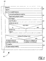
- FIG. 4 shows a first variant of an algorithm 60 for the operating program of the microcontroller 39. Since the Device 1 periodically determine the edge 2 of the web 3 is the operating program in the form of an endless loop 61 trained. At the beginning of the endless loop 61, the MaxS variable is initialized 62 and MaxI.
- a counting loop 63 follows. which run through once for each individual sensor 11 becomes. First, a measurement is made in the counting loop 63 64 performed in which the count variable i to the analog multiplexer 31 output as address and that on the analog-to-digital converter 37 applied voltage value S converted becomes.
- the measured voltage value S is then saved 65, being neighboring by calculating the differences Evaluate the first A and second derivative A2 of the Voltage values S is calculated. It is assumed that the individual sensors 11 to each other in the same Distance are arranged. So the distance is the Sensors 11 from each other only for the formation of the first A and second derivative A2 constant factor, see above that this distance can be disregarded.
- a Maximum search 66 of the first derivative A For this, the determined value of the first derivative A [i] with the variable MaxS compared and in the event that this value is greater than MaxS, as the new maximum of the first derivative A noted.
- the variable then contains MaxI at the end the counting loop 63 the number of that sensor 11 at which the first derivative A [MaxI] is maximum.
- the counting loop 63 is followed by a query 67 in which it determines becomes where the second derivative function A2 one Has a change of sign. Then there is a turning point W from the second derivatives A2 on both sides of the change of sign by linear interpolation between them calculated in step 68. Finally becomes the calculated turning point W in the final output step 69 issued in digital form and into one Analog value changed.
- the inflection point W could also be by interpolation a non-linear function, for example one Higher degree polynomial, which is calculated the accuracy of the inflection point calculation 68 accordingly improved. It is also conceivable instead of interpolation also an approximation of a fit function the method of minimizing the square distances the fit function from the stored values S, A or A2 to make. In this way, errors in the signals S a correspondingly smaller influence on the determination of the turning point W.
- FIG. 5 shows an alternative algorithm 60 which, in steps 62 to 66, corresponds to the proviso that the second derivative A2 is not calculated.
- a query 70 is carried out in which that side of the maximum of the derivation function A found on which the derivation function A is greatest.
- the Coefficients c and d are the inflection point W of the interpolation polynomial calculated.
- the output step 69 is again identical to the algorithm 60 according to FIG. 4.
Landscapes
- Physics & Mathematics (AREA)
- General Physics & Mathematics (AREA)
- Length Measuring Devices By Optical Means (AREA)
Description
Die Erfindung betrifft ein Verfahren zum Erfassen der Lage
einer laufenden Warenbahn gemäß dem Oberbegriff des
Patentanspruchs 1 sowie eine Vorrichtung zur Durchführung
dieses Verfahrens gemäß dem Oberbegriff des Patentanspruchs
9.The invention relates to a method for detecting the position
a running web according to the preamble of
Aus der DE 34 23 308 C2 ist eine fotoelektronische Fühleinrichtung bekannt, bei der eine Lichtquelle mehreren, unabhängig voneinander wirkenden Empfängerteilen gegenüberliegt. Die Empfängerteile werden von Halbleiter-Fotoelementen gebildet, die optisch an lichtsammelnden Kunststoffflächen angekoppelt sind. Jedes dieser Empfängerteile erfaßt einen bestimmten Bereich der Warenbahn, wobei das Fotoelement ein zur Bedeckung durch die Warenbahn proportionales Signal abgibt. Die Warenbahn-Kantenposition wird durch Vergleich der von den Fotoelementen abgegebenen Signale mit einem Schwellwert ermittelt. Dies hat jedoch den Nachteil, daß die mit dieser Fühleinrichtung erzielbare Auflösung im wesentlichen der Breite der Kunststoffplatten entspricht. Zur Erzielung einer hohen Auflösung bei gleichzeitig großem Meßbereich ist daher eine sehr große Anzahl an Fotoelementen erforderlich. Außerdem ist in diesem Fall eine sehr große Anzahl an Fotoelementen in jedem Meßzyklus abzufragen.DE 34 23 308 C2 describes a photoelectronic sensing device known, in which one light source several, opposite to each other acting receiver parts. The receiver parts are made of semiconductor photo elements formed optically on light-collecting Plastic surfaces are coupled. Each of these receiver parts covers a specific area of the web, wherein the photo element is a for covering by the web proportional signal. The web edge position is by comparing that of the photo elements emitted signals determined with a threshold. However, this has the disadvantage that the with this Sensing device achievable resolution essentially of Corresponds to the width of the plastic plates. To achieve a high resolution with a large measuring range therefore a very large number of photo elements is required. In addition, in this case there is a very large number of photo elements to be queried in every measuring cycle.
Aus der DE 42 09 546 C2 ist eine Vorrichtung zum Ermitteln der Lage der Kante einer laufenden Materialbahn bekannt, bei der mehreren, getrennt ansteuerbaren Lichtquellen jeweils ein Empfängerteil gegenüberliegt. Diese Empfängerteile geben ein zur Bedeckung der Warenbahn proportionales Signal ab, das mit einem Schwellwert verglichen wird. Das Vergleichsergebnis wird einem Mikrocomputer zugeführt, der in Abhängigkeit vom Vergleichsergebnis die Lichtquellen und Empfängerteile entsprechend einer sukzessiven Approximation ansteuert und auf diese Weise die Position der Warenbahnkante ermittelt. Zur Durchführung der sukzessiven Approximation muß eine Anzahl von Vergleichswerten der Empfängerteile mit dem Schwellwert in einer Speichereinheit des Mikrocomputers gespeichert werden.DE 42 09 546 C2 describes a device for determining the position of the edge of a running material web is known, with the multiple, separately controllable light sources one receiver part is opposite each other. This Receiver parts give a proportional to the coverage of the web Signal from that compared to a threshold becomes. The comparison result is a microcomputer fed, depending on the comparison result the light sources and receiver parts according to one successive approximation and in this way the position of the web edge is determined. To carry out the successive approximation must be a number of Comparison values of the receiver parts with the threshold value stored in a memory unit of the microcomputer become.
Der Erfindung liegt die Aufgabe zugrunde, ein Verfahren der eingangs genannten Art zu schaffen, das eine hohe Auflösung bei kurzer Meßzeit erzielt. Außerdem soll eine kostengünstige Vorrichtung zur Durchführung dieses Verfahrens geschaffen werden.The invention has for its object a method of the type mentioned at the outset to create a high Resolution achieved with a short measuring time. In addition, a inexpensive device for performing this method be created.
Diese Aufgabe wird mit den Verfahrensschritten des Patentanspruchs
1 sowie mit den Merkmalen des Patentanspruchs
9 gelöst.This task is accomplished with the procedural steps of the
Bei dem Verfahren gemäß Anspruch 1 wird die Warenbahn von
mehreren, quer zur Bahnlaufrichtung verteilten Sensoren
abgetastet. Jeder Sensor erzeugt dabei ein Signal, das
von der Abdeckung des Sensors durch die Warenbahn abhängig
ist. Vorzugsweise ist das vom Sensor erzeugte Signal
proportional zur Abdeckung durch die Warenbahn. Damit
liefert jeder Sensor ein von der Lage der Warenbahnkante
abhängiges Signal, wobei die einzelnen Sensoren in unterschiedlichen
Bereichen in Meßrichtung angeordnet sind.In the method according to
Vorzugsweise erfolgt die Abtastung der Warenbahn berührungslos, damit selbst empfindliche Warenbahnen nicht durch die Sensoren beschädigt werden. Außerdem wird auf diese Weise verhindert, daß die Sensoren selbst die Kantenerfassung stören, wie dies beispielsweise bei einem mechanischen Kantensensor der Fall ist, der mit Federkraft gegen die Bahnkante drückt. Bei etwa mittlerer Lage der Warenbahnkante sind die von der Bahnmitte aus betrachteten inneren Sensoren vollständig durch die Warenbahn abgedeckt, so daß diese Sensoren ein konstantes Ruhesignal abgeben. Die äußeren Sensoren sind dem gegenüber durch die Bahn in keiner Weise abgedeckt, so daß sie ein maximales Signal erzeugen. Die Sensoren im Bereich um die Warenbahnkante liefern Signale, die zwischen dem Ruhesignal und dem maximalen Signal liegen. Die Funktion der von den Sensoren erzeugten Signale von den Sensororten weist daher bei etwa mittlerer Kantenlage zwei konstante Bereiche unterschiedlicher Signalhöhe auf, zwischen denen ein stetiger Übergangsbereich vorgesehen ist. Bei extremer Lage der Warenbahnkante im Bereich des innersten oder äußersten Sensors kann einer der konstanten Bereiche auch fehlen, so daß eine Kantenbestimmung über Schwellwerte in diesem Fall sehr ungenau wird. Erfindungsgemäß wird daher vorgeschlagen, die Kantenposition aus dem Wendepunkt der Funktion der von den Sensoren erzeugten Signale von den Sensororten zu bestimmen. Dieser Wendepunkt ist auch bei extremer Lage der Bahnkante bestimmbar, selbst wenn die Sensorsignale bei vollständiger Abdeckung oder vollständiger Freigabe eines Sensors durch die Warenbahn nicht mehr ermittelt werden können. Vorzugsweise sind die einzelnen Sensoren äquidistant quer zur Warenbahnlaufrichtung verteilt, so daß der Sensorort besonders einfach durch Numerieren der Sensoren bestimmt werden kann. Damit kann die Ermittlung des Wendepunktes auch aus der Funktion der Sensorsignale von der Sensornummer bestimmt werden, wobei das Ergebnis der Wendepunktsuche in diesem Fall mit dem gegenseitigen Abstand der Sensoren zu multiplizieren ist. Allgemein kann der Wendepunkt auch aus einer Funktion der Sensorsignale von Werten, die zu den Sensororten proportional sind, bestimmt werden. Um eine korrekt skalierte Bahnkantenposition zu erhalten, muß der ermittelte Wendepunkt anschließend mit dem Proportionalitätsfaktor multipliziert werden. In jenen Fällen, in denen lediglich ein zur Kantenposition proportionales Signal benötigt wird, was beispielsweise bei Bahnführungseinrichtungen der Fall ist, kann auf eine entsprechende Korrektur des ermittelten Wendepunktes auch verzichtet werden.The web is preferably scanned without contact, not even sensitive webs damaged by the sensors. It will also be on this prevents the sensors themselves from edge detection disturb, like this for example with a mechanical edge sensor is the case with spring force presses against the web edge. At a medium location the web edge are those viewed from the center of the web inner sensors completely through the web covered, so that these sensors have a constant idle signal submit. The outer sensors are opposite not covered by the web in any way, making it a generate maximum signal. The sensors in the area around the Web edge provide signals between the idle signal and the maximum signal. The function of signals generated by the sensors from the sensor locations therefore two constant areas with approximately medium edge position different signal levels between which one continuous transition area is provided. At extreme Position of the web edge in the area of the innermost or outermost Sensor can be one of the constant ranges too are missing, so that edge determination via threshold values in this case becomes very inaccurate. According to the invention suggested the edge position from the inflection point of the Function of the signals generated by the sensors from the Determine sensor locations. This turning point is also at extreme position of the web edge can be determined, even if the Sensor signals with full coverage or more complete Approval of a sensor by the web is not can be determined more. The individual are preferred Sensors equidistant across the web direction distributed so that the sensor location is particularly easy can be determined by numbering the sensors. In order to can also determine the turning point from the function the sensor signals are determined by the sensor number, being the result of the turning point search in this Multiply the case by the mutual distance of the sensors is. In general, the turning point can also be from a Function of the sensor signals of values belonging to the Sensor locations are proportional, can be determined. To one to get correctly scaled web edge position, the determined inflection point with the proportionality factor be multiplied. In those cases where only a signal proportional to the edge position is needed, for example in web guiding devices the case may be on a corresponding one Correction of the determined turning point also waived become.
Bei dem Verfahren gemäß Anspruch 2 integriert der Sensor
sein Signal aus einem vorgegebenen Bereich, so daß kleinflächige
Ablagerungen auf der Sensorfläche nur noch geringen
Einfluß auf das vom Sensor erzeugte Signal haben.
Dies ist insbesondere bei stark fusselnden Warenbahnen
wichtig, da sich von der Warenbahn stammende Fusseln direkt
auf der Sensorfläche ablagern können. Hätten die
Sensoren eine wirksame Breite unterhalb ca. 1 mm, so
könnte jeder einzelne Fussel eine vollständige Abdeckung
eines Sensors hervorrufen, was irrtümlich als Warenbahnkante
gedeutet würde. Durch die großflächige Ausbildung
der wirksamen Sensorfläche können abgelagerte Fusseln lediglich
zu einer gleichmäßigen Dämpfung der Signale aller
Sensoren führen, was jedoch auf die Lage des Wendepunktes
keinerlei Einfluß hat. Damit wird durch diese Maßnahme
eine erhöhte Schmutzunempfindlichkeit der Kantenfühleinrichtung
erreicht. Da der Wendepunkt wesentlich genauer
bestimmt werden kann als der Abstand der einzelnen Sensoren,
geht diese Maßnahme auch nicht zu Lasten der Genauigkeit
der Kantenbestimmung.In the method according to
Die in Anspruch 3 vorgeschlagenen Methoden zur Erfassung
der Warenbahnabdeckung arbeiten berührungslos und stören
demnach in keiner Weise den Bahnlauf. Außerdem können auf
diese Weise auch besonders empfindliche Warenbahnen sicher
erfaßt werden, ohne daß die Gefahr einer Beschädigung
der Warenbahn oder einer Meßwertverfälschung besteht.
Eine optische Erfassung der Warenbahnabdeckung erfolgt
entweder im Reflexionsverfahren oder im Lichtschrankenprinzip.
Dabei wird die Warenbahn von mindestens
einer Lichtquelle beleuchtet, wobei lichtempfindliche
Empfänger entweder an der der Warenbahn gegenüberliegenden
Seite oder neben der Lichtquelle vorgesehen sind. Alternativ
könnte die Warenbahnabdeckung auch auf pneumatischem
Wege mittels Luftstrahlen abgetastet werden, wobei
in diesem Fall druckempfindliche Sensoren vorzusehen
sind. Bei einer akustischen Abtastung der Warenbahn werden
Schallwellen gegen die Warenbahn gerichtet, die von
Mikrophonen erfaßt werden.The detection methods proposed in
Eine besonders einfache und damit störsichere Erfassung
des Wendepunktes ergibt sich aus Anspruch 4. Dabei wird
die Funktion der Signale vom Sensorort zweimal numerisch
differenziert und aus der zweiten Ableitungsfunktion eine
Nullstelle ermittelt. Die der Kantenposition entsprechende
Nullstelle der zweiten Ableitung befindet sich im Bereich
der größten Steigung, also bei einem Maximalwert
der ersten Ableitung. Aus diesen Bedingungen kann die
Kantenposition mit geringem Rechenaufwand genau ermittelt
werden.A particularly simple and therefore interference-free detection
of the inflection point follows from
Alternativ kann der Wendepunkt gemäß Anspruch 5 auch
durch einfaches numerisches Differenzieren und numerisches
Suchen des Maximums der ersten Ableitungsfunktion
bestimmt werden. Auf diese Weise wird eine zweite Differenziation
eingespart, wobei jedoch die Suche des Maximums
der ersten Ableitungsfunktion numerisch aufwendiger
ist. Diese Methode hat jedoch den Vorteil, daß die Bedingung,
das absolute Maximum zu suchen, ohne weitere Nebenbedingung
die Lage der Bahnkante liefert.Alternatively, the turning point according to
Als weitere Alternative wird gemäß Anspruch 6 vorgeschlagen,
an die von den Sensoren erzeugte Funktion der Signale
vom Sensorort eine Fitfunktion anzunähern, wobei der
Wendepunkt unmittelbar aus den Fitparametern berechnet
wird. Die Annäherung der Fitfunktion an die Signale der
Sensoren erfolgt vorzugsweise nach der Methode der Minimierung
der Quadrate der Abweichungen der Signale von den
entsprechenden Funktionswerten der Fitfunktion. Der Wendepunkt
kann im allgemeinen analytisch durch zweimaliges
Differenzieren und Nullsetzen der Fitfunktion berechnet
werden, so daß je nach Fitfunktion eine mehr oder weniger
einfache Formel zur Berechnung des Wendepunktes aus den
Fitparametern angegeben werden kann.As a further alternative, it is proposed according to
Vorzugsweise wird als Fitfunktion gemäß Anspruch 7 ein
Polynom eingesetzt, dessen Koeffizienten die Fitparameter
sind. Aus diesem Polynom läßt sich sehr einfach die zweite
Ableitung analytisch berechnen, so daß aus den Polynom-Koeffizienten
direkt der Wendepunkt ermittelt werden
kann.Preferably, a fit function according to
Gemäß Anspruch 8 wird vorgeschlagen, die Signale der einzelnen Sensoren durch das Signal eines Referenz-Sensors zu dividieren. Durch diese Maßnahme können Meßfehler, die beispielsweise von einer sich ändernden Beleuchtungsstärke des Senders herrühren, eliminiert werden. Werden die Signale des Sensors und des Referenzsensors zeitnah erfaßt, so können auch kurzzeitige Schwankungen des Senders ausgeglichen werden. Vorzugsweise wird jeweils ein Sensor alternierend mit dem Referenzsensor abgefragt, um Senderschwankungen möglichst optimal auszugleichen.According to claim 8, the signals of the individual are proposed Sensors by the signal of a reference sensor to divide. This measure can measuring errors for example, from a changing illuminance originate from the transmitter, be eliminated. Will the Signals from the sensor and the reference sensor are recorded promptly, this can also cause short-term fluctuations in the transmitter be balanced. A sensor is preferably used in each case alternately queried with the reference sensor to determine transmitter fluctuations balance as optimally as possible.
Die Vorrichtung gemäß Anspruch 9 hat sich zur Durchführung des erfindungsgemäßen Verfahrens besonders bewährt. Diese Vorrichtung weist mehrere Sensoren auf, die jeweils ein von der Bedeckung der Bahn abhängiges Signal erzeugen. Diese Sensoren sind vorzugsweise quer zur Bahnlaufrichtung in Reihe nebeneinandergesetzt. Alternativ könnten sie auch zickzackartig zueinander versetzt angeordnet sein. Wichtig ist, daß die einzelnen Sensoren von einer feststehend gedachten Bahnkante unterschiedliche Abstände aufweisen. Dadurch wird erreicht, daß jeder Sensor in einem bestimmten Breitenbereich auf Änderungen der Bahnkante reagiert. Wird der Sensor dagegen vollständig von der Bahn abgedeckt, so erzeugt er lediglich ein Ruhesignal. Wird der Sensor von der Bahn überhaupt nicht abgedeckt, so erzeugt er ein maximales aktives Signal. Die einzelnen Sensoren sind über Schaltmittel mit einem Analog-Digital-Umsetzer verbunden. Durch diese Schaltmittel wird erreicht, daß die Signale der einzelnen Sensoren nacheinander abgefragt und in einen Digitalwert umgewandelt werden können. Diese Schaltmittel stehen mit Speichermitteln in Wirkverbindung, in denen die digitalisierten Werte gespeichert werden. Auf diese Speichermittel kann ein Wendepunkt-Detektor zugreifen, der aus der Funktion der digitalisierten Werte von den Sensororten einen Wendepunkt ermittelt. Der vom Wendepunkt-Detektor errechnete Digitalwert wird an einem Digitalausgang ausgegeben und steht damit weiteren Vorrichtungen, wie Bahnkantenreglern oder Anzeigeinstrumenten zur Verfügung.The device according to claim 9 has been implemented of the method according to the invention particularly proven. This device has several sensors, each generate a signal dependent on the coverage of the web. These sensors are preferably transverse to the web running direction placed in a row next to each other. Alternatively, you could they also zigzag staggered his. It is important that the individual sensors from one fixed imaginary web edge different distances exhibit. This ensures that each sensor in one certain width range on changes in web edge responds. However, if the sensor is completely removed from the Path covered, it only generates a rest signal. If the sensor is not covered by the web at all, so it generates a maximum active signal. The single ones Sensors are via switching means with an analog-to-digital converter connected. This switching means that the signals from each sensor are sequential queried and converted into a digital value can. These switching means are available with storage means in Active connection in which the digitized values are stored become. A turning point detector can be placed on these storage means access that from the function of digitized Values from the sensor locations a turning point determined. The digital value calculated by the inflection point detector is output at a digital output and stands thus other devices such as web edge regulators or Display instruments available.
Um die gewünschte integrierende Wirkung der einzelnen
Sensoren mit einfachsten Mitteln sicherzustellen, wird
gemäß Anspruch 10 vorgeschlagen, den Sensor als Fotodetektor
mit zugeordneter Platte aus lichtsammelndem Kunststoff
auszubilden. In der Kunststoffplatte ist ein fluoreszierender
Stoff enthalten, der das von der Lichtquelle
ankommende Licht in langwelligeres Licht umwandelt, das
sich bevorzugt in der Plattenebene ausbreitet. Der Fotodetektor
wird stirnseitig an die Platte angekoppelt, so
daß er ein sehr starkes und damit störunempfindliches
Lichtsignal empfängt. Durch das Auftreten von Totalreflexionen
des Lichts an den Plattenflächen verteilt sich das
Licht gleichmäßig über die gesamte Platte, so daß der
Sensor ein zur Abdeckung durch die Warenbahn exakt proportionales
Signal liefert. Es spielt dabei keine Rolle,
ob das Licht gleichmäßig verteilt oder nur an einer bestimmten
Stelle in die Kunststoffplatte eindringt.To the desired integrating effect of each
To ensure sensors with the simplest means
proposed according to
Insbesondere bei großem Abstand zwischen der Lichtquelle und den Sensoren wird die Erfassung der Bahnkante durch schräg zur Warenbahnebene gerichtete Lichtstrahlen beeinträchtigt. In diesem Fall ist es gemäß Anspruch 11 vorteilhaft, zwischen der Lichtquelle und den Sensoren ein die Lichtstrahlen parallelisierendes Element vorzusehen. Dieses Element ist im einfachsten Fall ein Körper mit einer Vielzahl von senkrecht zur Warenbahn ausgerichteten Flächen. Beispielsweise könnte das Element von Rohrstükken, zueinander parallelen Wänden oder einer Wabenstruktur gebildet sein. Alternativ könnte das Element von einer Reihe von Linsen oder einem Bündel Glas- oder Kunststoffasern gebildet sein. Wichtig ist lediglich, daß die Lichtstrahlen, in Erfassungsrichtung der Vorrichtung gesehen, parallel zueinander ausgerichtet sind. In Warenbahnlaufrichtung gesehen, spielen dagegen unterschiedliche Strahlrichtungen des Lichtes nur eine untergeordnete Rolle.Especially when there is a large distance between the light source and the sensors are used to detect the web edge Light rays directed at an angle to the web level are impaired. In this case it is advantageous according to claim 11 between the light source and the sensors to provide the element parallelizing the light rays. In the simplest case, this element is a body with a Variety of perpendicular to the web Surfaces. For example, the element of pipe pieces, parallel walls or a honeycomb structure be educated. Alternatively, the item could be from a Row of lenses or a bundle of glass or plastic fibers be educated. It is only important that the Light rays, seen in the direction of detection of the device, are aligned parallel to each other. In the direction of the web seen, however, play different Beam directions of light only a subordinate Role.
Eine besonders einfache Realisierung der Schaltmittel zur
zeitlich versetzten Abfrage der Sensoren ergibt sich aus
Anspruch 12 in Form eines Analogmultiplexers. Ein Analogmultiplexer
ist als integrierte Schaltung verfügbar und
damit unempfindlich gegenüber Chemikalien und erhöhten
Temperaturen, wie sie bei der Bearbeitung von textilen
Warenbahnen auftreten. Damit die von den Sensoren erzeugten
Signale durch den nicht vernachlässigbaren On-Widerstand
des Analogmultiplexers nicht verfälscht werden,
werden die Signale nicht als Spannungs-, sondern als
Strom-Werte übertragen. Um eine nachfolgende Analog-Digital-Wandlung
zu ermöglichen, ist dem Analogmultiplexer
ein Strom-Spannungs-Wandler nachgeordnet, der eine
dem Sensorstrom proportionale Spannung erzeugt.A particularly simple implementation of the switching means for
time-delayed query of the sensors results from
Insbesondere beim Einsatz in sehr heißer Umgebung muß die Vorrichtung eine gewisse Wärmeausdehnung verkraften können. Da die einzelnen Komponenten der Vorrichtung von unterschiedlichen Materialien gebildet werden, ist es in diesem Fall erforderlich, die empfindlichen Platinen, auf denen die Sensorelektronik aufgebracht ist, um ein gewisses Maß dehnbar zu gestalten. Es wird deshalb gemäß Anspruch 13 vorgeschlagen, die Platinen, die die Sensoren tragen, wenigstens teilweise flexibel auszubilden. Es ist dabei vorstellbar, die gesamten Sensoren auf mindestens einer, über ihre gesamte Länge flexible Platine aufzubauen. Alternativ können die Sensoren auch modulartig auf harten Platinen untergebracht werden, wobei zwischen den einzelnen Modulen jeweils eine flexible Verbindung, beispielsweise in Form von Kabeln, vorgesehen ist.Especially when used in a very hot environment Device can cope with a certain thermal expansion. Since the individual components of the device differ Materials are formed, it is in In this case, the sensitive circuit boards are required to which the sensor electronics are attached to a certain extent To be made dimensionally stretchable. It is therefore according to claim 13 proposed the boards that the sensors wear, at least partially flexible training. It is conceivable, the entire sensors at least one to build flexible board over its entire length. Alternatively, the sensors can also be modular hard boards are housed, with between the individual modules each have a flexible connection, for example in the form of cables.
Der Wendepunkt-Detektor stellt eine schaltungstechnisch aufwendige Vorrichtung dar, so daß es gemäß Anspruch 14 günstig ist, diesen als Controller auszubilden. Damit können die erforderlichen Rechenschritte durch ein entsprechendes Betriebsprogramm realisiert werden, so daß sich der schaltungstechnische Aufwand in vertretbaren Grenzen hält. Vorzugsweise ist auch der erforderliche Analog-Digital-Umsetzer als Teil des Controllers ausgebildet, wodurch sich der schaltungstechnische Aufwand noch weiter verringert.The turning point detector provides a circuitry complex device, so that it according to claim 14 it is favorable to train this as a controller. In order to can perform the necessary arithmetic steps by means of a corresponding Operating program can be realized so that the circuitry effort in reasonable Limits. The one required is also preferred Analog-digital converter designed as part of the controller, which increases the circuit complexity reduced even further.
Schließlich ist es gemäß Anspruch 15 vorteilhaft, dem Wendepunkt-Detektor mindestens einen Digital-Analog-Umsetzer nachzucrdnen, der ggf. ebenfalls als Teil des Controllers ausgebildet sein kann. Der Digital-Analog-Umsetzer erzeugt ein dem Wendepunkt und damit der Kantenposition proportionales Analog-Signal, das direkt einem Bahnkanten-Regler zugeführt werden kann.Finally, it is advantageous according to claim 15 Turning point detector at least one digital-to-analog converter which may also be part of the Controller can be formed. The digital-to-analog converter creates the inflection point and thus the edge position proportional analog signal that directly one Web edge controller can be fed.
Der Erfindungsgegenstand und das erfindungsgemäße Verfahren werden anhand der Zeichnung beispielhaft beschrieben, ohne den Schutzumfang zu beschränken. The subject of the invention and the method according to the invention are described using the drawing as an example, without restricting the scope of protection.
Es zeigt:
Figur 1- eine Schnittdarstellung durch eine Vorrichtung zur Kantenerfassung einer Warenbahn,
Figur 2- ein Prinzip-Schaltbild der Vorrichtung gemäß Figur 1,
Figur 3- eine Darstellung der Sensorsignale als Funktion der Sensororte,
Figur 4- einen Algorithmus zur Kantenbestimmung und
Figur 5- einen alternativen Algorithmus zur Kantenbestimmung.
- Figure 1
- 2 shows a sectional illustration through a device for edge detection of a material web,
- Figure 2
- 2 shows a basic circuit diagram of the device according to FIG. 1,
- Figure 3
- a representation of the sensor signals as a function of the sensor locations,
- Figure 4
- an algorithm for edge determination and
- Figure 5
- an alternative algorithm for edge determination.
Figur 1 zeigt eine Schnittdarstellung einer Vorrichtung 1
zur Lageerfassung einer Kante 2 von einer Warenbahn 3.
Die Vorrichtung 1 weist eine Lichtquelle 4 in Form einer
Leuchtstoffröhre auf, die Lichtstrahlen 5, 5' gegen die
Warenbahn 3 aussendet. Je nach Lage der Kante 2 der Warenbahn
3 wird ein kleinerer oder größerer Anteil der
Lichtstrahlen 5, 5' von der Warenbahn 3 absorbiert oder
reflektiert, während der andere Teil der Lichtstrahlen 5,
5' durch die Warenbahn 3 in keiner Weise beeinflußt wird.FIG. 1 shows a sectional illustration of a
Die Lichtstrahlen 5, 5' passieren anschließend ein optisches
Element 6, das von mehreren senkrecht zur Warenbahn
3 ausgerichteten Wänden 7 gebildet ist. Lichtstrahlen 5',
die im Winkel zu den Wänden 7 verlaufen, werden von den
Wänden 7 absorbiert, so daß lediglich jene Lichtstrahlen
5 das optische Element 6 passieren können, die annähernd
senkrecht zur Warenbahn 3 verlaufen. Auf diese Weise wird
eine scharfe Kantenabbildung durch die Lichtstrahlen 5
erreicht. The light beams 5, 5 'then pass an
Nach dem Passieren des optischen Elements 6 treffen die
Lichtstrahlen 5 auf eine Sensoreinheit 10, die von mehreren
Sensoren 11 gebildet ist. Jeder Sensor 11 besteht aus
einem lichtempfindlichen Element in Form einer Fotodiode
12, wobei eine lichtempfindliche Fläche 13 der Fotodiode
12 in einer Bohrung 14 einer Kunststoffplatte 15
vorgesehen ist. Die Dicke D der Kunststoffplatte 15 ist
dabei an die Höhe der lichtempfindlichen Fläche 13 der
Fotodiode 12 angepaßt.After passing through the
In der Kunststoffplatte 15 ist ein fluoreszierender Farbstoff
eingebaut, der die einfallenden Lichtstrahlen 5 in
langwelligere Lichtstrahlen 16 umwandelt. Diese langwelligen
Lichtstrahlen 16 breiten sich bevorzugt annähernd
in der Ebene der Kunststoffplatte 15 aus und werden daher
an den oberen und unteren Grenzflächen 17 der Kunststoffplatte
15 total reflektiert. Die langwelligen Lichtstrahlen
16 treten daher vornehmlich an den Stirnflächen 18
sowie an der Wand der Bohrung 14 aus der Kunststoffplatte
15 aus. Dies gewährleistet, daß ein verhältnismäßig großer
Anteil des in die Kunststoffplatte 15 einfallenden
Lichtes 5 die lichtempfindliche Fläche 13 der Fotodiode
12 erreicht, so daß diese einen entsprechend hohen Fotostrom
abgibt. Dies reduziert die Störempfindlichkeit der
Vorrichtung 1, wobei die einzelnen Sensoren eine vorteilhafte
integrierende Wirkung über die Plattenfläche von
vorzugsweise ca. 15 cm2 aufweisen. Die Sensoren sind deshalb
unempfindlich gegen punktuelle Verschmutzung.A fluorescent dye is installed in the
Die Kunststoffplatten 15 sind auf einem gemeinsamen Träger
11 gehalten, der vorzugsweise gegenüber der Warenbahn
3 abgedichtet ist. Dies ist insbesondere in jenen
Fällen wichtig, in denen die Vorrichtung 1 im Naßbereich
eingesetzt wird, wo die Warenbahn 3 zum Teil mit ätzenden
Chemikalien behandelt wird. Der dichte Abschluß des Trägers
20 gegenüber der Warenbahn 3 sorgt für einen ausreichenden
Schutz der Sensoreinheit 10 gegenüber den Chemikalien.The
Die Fotodioden 12 sind auf Platinen 21 aufgelötet, die im
Gegensatz zum Träger 20 aus mehreren Einzelteilen zusammengesetzt
sind. Dies hat zum einen den Vorteil einer
einfacheren Herstellung der Platinen 21, insbesondere für
große Sensorlängen. Zum anderen können sich die Platinen
21 gegenüber dem Träger 20 um ein gewisses Maß ausdehnen,
ohne die empfindliche Leiterbahnschicht auf den Platinen
21 zu beschädigen. Dies ist insbesondere in jenen Fällen
wichtig, in denen die Vorrichtung 1 einer erhöhten Temperatur,
beispielsweise bis 105° C, ausgesetzt ist. Die
Verbindung zwischen den einzelnen Platinen 21 erfolgt im
einfachsten Fall durch einen flexiblen Abschnitt 22 in
Form eines mehradrigen Kabels. Alternativ könnte auch die
gesamte Platine 21 aus flexiblen Material, wie einer kupferkaschierten
Folie, hergestellt sein.The
Figur 2 zeigt einen schematischen Schaltplan der Vorrichtung
1. Das von der Lichtquelle 4 ausgesendete Licht 5
passiert die Warenbahn 3, sowie das optische Element 6
und wird von Fotodioden 12 detektiert. Die Fotodioden 12
sind kathodenseitig an einer Referenzspannungsquelle 30
angeschlossen, um an den Fotodioden 12 eine ausreichende
Sperrspannung anzulegen. Alternativ könnten die Fotodioden
12 auch als Fotoelemente geschaltet sein, wobei
dann zur Unterdrückung kapazitiver Stromspitzen Widerstände
zu diesen parallel geschaltet sind.Figure 2 shows a schematic circuit diagram of the
Die Fotodioden 12 sind anodenseitig mit einem Analogmultiplexer
31 verbunden, der entsprechend den logischen Pegeln
an seinen Adreßeingängen 32 einen ausgewählten Eingang
33 mit einem Ausgang 34 verbindet. Der Ausgang 34
des Analogmultiplexers 31 ist mit einem Strom-Spannungs-Wandler
35 verbunden, der den Ausgang 34 des Analogmultiplexers
31 auf Masse zieht. Damit kann die aufgrund der
Pegel an den Adreßeingängen 32 ausgewählte Fotodiode 12
ihren Fotostrom über den Analogmultiplexer 31 in den
Strom-Spannungs-Wandler 35 leiten, der diesen Fotostrom
in eine hierzu proportionale Spannung umwandelt. Durch
diesen Aufbau ist sichergestellt, daß der nicht vernachlässigbare
On-Widerstand des Analogmultiplexers 31 keinerlei
Einfluß auf das von der Fotodiode 12 erzeugte Fotosignal
hat.The
Ein Ausgang 36 des Strom-Spannungs-Wandlers 35 ist mit
einem Analog-Digital-Umsetzer 37 verbunden, der einen dem
Fotostrom entsprechenden Digitalwert erzeugt. Diese Digitalwerte
gelangen über einen Signalweg 42 in einen Mikrocontroller
39, der die einzelnen Digitalwerte zunächst in
einer Speichereinheit 40 ablegt.An
Im Mikrocontroller 39 ist ein Betriebsprogramm abgelegt,
das Adressen für den Analogmultiplexer 31 erzeugt und
diese an einen Adreßausgang 41 anlegt. Außerdem sorgt
dieses Betriebsprogramm für die Ansteuerung des Analog-Digital-Umsetzers
37 über den Signalweg 42 und den Empfang
der digitalisierten Werte über den Signalweg 38. Das
Betriebsprogramm des Mikrocontrollers bewirkt außerdem
die Ablage der digitalisierten Werte in der Speichereinheit
40 und die Berechnung eines Wendepunktes aus den gespeicherten
Daten. Schließlich sorgt das Betriebsprogramm
für eine Ausgabe des ermittelten Wendepunktes an einem
Ausgang 43 und für die Ansteuerung eines Digital-Analog-Umsetzers
44, der den Digitalwert am Ausgang 43 in eine
Analogspannung umsetzt und an einem Analogausgang 45 ausgibt.
Der am Digitalausgang 43 und am Analogausgang 45
anstehende Wert entspricht der Position der Kante 2 der
Warenbahn 3 und kann von weiteren Vorrichtungen, wie beispielsweise
Kantenreglern oder Anzeigeeinheiten, benutzt
werden.An operating program is stored in the
Figur 3 zeigt eine schematische Darstellung der von den
Sensoren 11 ermittelten Signale S als Funktion des jeweiligen
Sensorortes. Die Signale S der einzelnen Sensoren
sind jeweils als Balken dargestellt. Die Signale S ergeben
zusammen eine Funktion 51 vom jeweiligen Sensorort,
die in Form einer Kurve dargestellt ist. Bestimmt man von
dieser Funktion 51 einen Wendepunkt W, so ergibt dieser
mit ausreichender Genauigkeit die Lage der Kante 2 der
Warenbahn 3, wobei der Wendepunkt W unabhängig vom maximalen
Signal 53 und vom Ruhesignal 54 ist.Figure 3 shows a schematic representation of the
Figur 4 zeigt eine erste Variante eines Algorithmus 60
für das Betriebsprogramm des Mikrocontrollers 39. Da die
Vorrichtung 1 periodisch die Kante 2 der Warenbahn 3 bestimmen
soll, ist das Betriebsprogramm in Form einer Endlosschleife
61 ausgebildet. Am Beginn der Endlosschleife
61 erfolgt eine Initialisierung 62 der Variablen MaxS
und MaxI.FIG. 4 shows a first variant of an
Nach der Initialisierung 62 folgt eine Zählschleife 63,
die für jeden einzelnen Sensor 11 einmal durchlaufen
wird. In der Zählschleife 63 wird zunächst eine Messung
64 durchgeführt, in dem die Zählvariable i an den Analogmultiplexer
31 als Adresse ausgegeben und der am Analog-Digital-Umsetzer
37 anliegende Spannungswert S gewandelt
wird.After
Der gemessene Spannungswert S wird anschließend gespeichert
65, wobei durch Berechnung der Differenzen benachbarter
Werte die erste A und zweite Ableitung A2 der
Spannungswerte S berechnet wird. Dabei ist vorausgesetzt,
daß die einzelnen Sensoren 11 zueinander im jeweils gleichen
Abstand angeordnet sind. Damit ist der Abstand der
Sensoren 11 voneinander lediglich ein für die Bildung der
ersten A und zweiten Ableitung A2 konstanter Faktor, so
daß dieser Abstand unberücksichtigt bleiben kann.The measured voltage value S is then saved
65, being neighboring by calculating the differences
Evaluate the first A and second derivative A2 of the
Voltage values S is calculated. It is assumed
that the
Nach dem Speichern 65 der Spannungswerte S erfolgt eine
Maximumsuche 66 der ersten Ableitung A. Hierzu wird der
ermittelte Wert der ersten Ableitung A [i] mit der variablen
MaxS verglichen und für den Fall, daß dieser Wert
größer als MaxS ist, als neues Maximum der ersten Ableitung
A gemerkt. Damit enthält die Variable MaxI am Ende
der Zählschleife 63 die Nummer jenes Sensors 11, bei dem
die erste Ableitung A [MaxI] maximal ist. After the voltage values S have been stored 65, a
Nach vollständigem Durchlauf aller Schleifendurchgänge
der Zählschleife 63 erfolgt eine Abfrage 67, in der bestimmt
wird, wo die zweite Ableitungsfunktion A2 einen
Vorzeichenwechsel aufweist. Anschließend wird ein Wendepunkt
W aus den zweiten Ableitungen A2 beidseits des Vorzeichenwechsels
durch lineare Interpolation zwischen diesen
beiden Werten im Schritt 68 berechnet. Schließlich
wird der berechnete Wendepunkt W im abschließenden Ausgabeschritt
69 in digitaler Form ausgegeben und in einen
Analogenwert gewandelt.After all loops have been completed
the
Alternativ könnte der Wendepunkt W auch durch Interpolation einer nicht linearen Funktion, beispielsweise einem Polynom höheren Grades, berechnet werden, wodurch sich die Genauigkeit der Wendepunktsberechnung 68 entsprechend verbessert. Außerdem ist es denkbar, anstatt einer Interpolation auch eine Approximation einer Fitfunktion mit der Methode der Minimierung der quadratischen Abstände der Fitfunktion von den gespeicherten Werten S, A oder A2 vorzunehmen. Auf diese Weise haben Fehler der Signale S einen entsprechend geringeren Einfluß auf die Bestimmung des Wendepunktes W.Alternatively, the inflection point W could also be by interpolation a non-linear function, for example one Higher degree polynomial, which is calculated the accuracy of the inflection point calculation 68 accordingly improved. It is also conceivable instead of interpolation also an approximation of a fit function the method of minimizing the square distances the fit function from the stored values S, A or A2 to make. In this way, errors in the signals S a correspondingly smaller influence on the determination of the turning point W.
Figur 5 zeigt einen alternativen Algorithmus 60, der in
den Schritten 62 bis 66 mit der Maßgabe übereinstimmt,
daß die zweite Ableitung A2 nicht berechnet wird. Nach
Durchlauf aller Schleifendurchgänge 63 erfolgt eine Abfrage
70, in der jene Seite des gefundenen Maximums der
Ableitungsfunktion A bestimmt wird, auf der die Ableitungsfunktion
A am größten ist. Anschließend wird ein Polynom
dritten Grades durch Interpolation 71 an vier aufeinanderfolgenden
Werten S der gespeicherten Signale bestimmt.
Dieses Polynom hat dabei die allgemeine Form:
Da der konstante a und der lineare Koeffizient b für die
Berechnung des Wendepunktes W nicht benötigt werden, kann
auf die Berechnung dieser Koeffizienten a, b bei der Interpolation
71 verzichtet und nur die Koeffizienten c, d
berechnet werden. In einem Schritt 68 wird aus den
Koeffizienten c und d der Wendepunkt W des Interpolationspolynoms
berechnet. Der Ausgabeschritt 69 ist wiederum
zum Algorithmus 60 gemäß Figur 4 identisch.Since the constant a and the linear coefficient b for the
Calculation of the inflection point W may not be required
on the calculation of these coefficients a, b during
Claims (15)
- Method of detecting the position of an edge (2) of a moving product web (3), in which the product web (3) is scanned by a plurality of sensors (11) which are distributed transversely with respect to the product running direction and which each generate a signal (S) that depends on being covered by the product web (3), a digital and/or analogue output signal being emitted, characterized in that the function (51) of the signals (S) that are generated by the sensors (11) values proportional to the sensor locations is used to determine a point of inflection (W), and the output signal emitted is proportional to the point of inflection (W) determined.
- Method according to Claim 1, characterized in that the sensor (11) is integrated over a predefined area transverse to the web running direction.
- Method according to Claim 1 or 2, characterized in that the covering by the product web is registered in an optical, pneumatic or acoustic way.
- Method according to at least one of Claims 1 to 3, characterized in that the point of inflection (W) is determined by twofold; numeric differentiation (65) of the function (51) of the signals (S) that are generated by the sensors (11) from values proportional to the sensor locations, a zero point of the second derivative function (A2) determined being calculated by means of interpolation or approximation (68).
- Method according to at least one of Claims 1 to 3, characterized in that the point of inflection (W) is determined by numeric differentiation (65) of the function (51) of the signals (S) that are generated by the sensors (11) from values proportional to the sensor locations, the maximum of the derivative function (A) determined being calculated by means of interpolation or approximation.
- Method according to at least one of Claims 1 to 3, characterized in that the point of inflection (W) is determined by means of interpolation or approximation (68) of a fit function to the function (51) of the signals (S) that are generated by the sensors (11) from values proportional to the sensor locations, the point of inflection (W) being calculated from the fit parameters (c, d) determined.
- Method according to Claim 6, characterized in that the fit function is a polynomial.
- Method according to at least one of Claims 1 to 6, characterized in that the signal (S) from the sensor (11) is scaled by a signal (S) from a reference sensor, the two signals (S) being registered contemporaneously.
- Device for detecting the position of an edge (2) of a moving product web (3), the device (1) having a plurality of sensors (11) which are distributed transversely with respect to the web running direction and which each generate a signal (S) which depends on being covered by the product web (3), and which are operatively connected via switching means (31) to an analogue/digital converter (37), with which storage means (40) for storing the digitized values (S) are associated, characterized in that the storage means (40) are operatively connected to a point-of-inflection detector (39) which determines a point of inflection (W) from the function (51) of the digitized values (S) of values proportional to the sensor locations.
- Device according to Claim 9, characterized in that the sensor (11) has a plate (15) that consists of light-collecting plastic which is associated with a photodetector (12), at least one light source (4) being provided opposite the sensors (11).
- Device according to Claim 10, characterized in that an element (6) which collimates light beams (5, 5') is provided between the light source (4) and the sensors (11).
- Device according to at least one of Claims 9 to 11, characterized in that the switching means (31) are formed by at least one analogue multiplexer (31), downstream of which at least one current/voltage converter (35) is arranged.
- Device according to at least one of Claims 9 to 12, characterized in that the sensors (11) are constructed on circuit boards (21) which are of at least partially flexible design.
- Device according to at least one of Claims 9 to 13, characterized in that the point-of-inflection detector (39) and/or the analogue/digital converter (37) are/is implemented by means of at least one microcontroller (46).
- Device according to at least one of Claims 9 to 14, characterized in that at least one digital/analogue converter (44) is arranged downstream of the point-of-inflection detector (39).
Applications Claiming Priority (2)
| Application Number | Priority Date | Filing Date | Title |
|---|---|---|---|
| DE19924798 | 1999-05-29 | ||
| DE19924798A DE19924798C1 (en) | 1999-05-29 | 1999-05-29 | Method and device for detecting the position of an edge of a running web |
Publications (2)
| Publication Number | Publication Date |
|---|---|
| EP1058087A1 EP1058087A1 (en) | 2000-12-06 |
| EP1058087B1 true EP1058087B1 (en) | 2001-12-12 |
Family
ID=7909694
Family Applications (1)
| Application Number | Title | Priority Date | Filing Date |
|---|---|---|---|
| EP00110943A Expired - Lifetime EP1058087B1 (en) | 1999-05-29 | 2000-05-25 | Position recording of an edge with distributed sensors by determining the turning point |
Country Status (3)
| Country | Link |
|---|---|
| US (1) | US6348696B1 (en) |
| EP (1) | EP1058087B1 (en) |
| DE (2) | DE19924798C1 (en) |
Families Citing this family (13)
| Publication number | Priority date | Publication date | Assignee | Title |
|---|---|---|---|---|
| DE10223754A1 (en) * | 2002-05-28 | 2004-01-22 | Siemens Ag | Circular knitting machine for textile mesh products with fault sensor and optical or acoustic fault warning |
| DE10312872A1 (en) * | 2003-03-22 | 2004-10-14 | Nexpress Solutions Llc | Optical detector, for sensing position of object in detection region, has adjustable mirror to direct light from source to receiver and determines object position from interruption of light path |
| GB2424269A (en) * | 2004-04-01 | 2006-09-20 | Robert Michael Lipman | Control apparatus |
| US7415881B2 (en) * | 2004-08-19 | 2008-08-26 | Fife Corporation | Ultrasonic sensor system for web-guiding apparatus |
| US7379194B2 (en) * | 2005-10-11 | 2008-05-27 | Pitney Bowes Inc. | Method and system for determining mail piece dimensions using swept laser beam |
| WO2008107892A1 (en) * | 2007-03-06 | 2008-09-12 | Advanced Vision Technology (Avt) Ltd. | System and method for detecting the contour of an object on a moving conveyor belt |
| DE102009022316B3 (en) * | 2009-05-22 | 2010-08-19 | Eastman Kodak Company | Method and device for detecting a substrate edge in a printing machine |
| US8666188B2 (en) * | 2011-03-23 | 2014-03-04 | Xerox Corporation | Identifying edges of web media using textural contrast between web media and backer roll |
| US9415963B2 (en) | 2013-01-30 | 2016-08-16 | Fife Corporation | Sensor controller for interpreting natural interaction sensor for web handling |
| EP2876467A1 (en) | 2013-11-25 | 2015-05-27 | Sick Ag | Light grid |
| DE102017010880A1 (en) * | 2017-11-24 | 2019-05-29 | Texmag Gmbh Vertriebsgesellschaft | Sensor for detecting at least one edge of a moving web |
| DE102020104931B4 (en) * | 2020-02-25 | 2021-11-18 | Balluff Gmbh | Method and device for edge detection of an object |
| EP3991860A1 (en) * | 2020-11-02 | 2022-05-04 | Industrial Technology Research Institute | Textile detection module, textile sorting system and using method thereof |
Family Cites Families (19)
| Publication number | Priority date | Publication date | Assignee | Title |
|---|---|---|---|---|
| FR2036090A5 (en) * | 1969-03-04 | 1970-12-24 | Cetih | |
| US3907439A (en) * | 1973-08-14 | 1975-09-23 | Zygo Corp | Edge-sensing with a scanning laser beam |
| JPS5081358A (en) * | 1973-11-20 | 1975-07-02 | ||
| JPS55112585A (en) * | 1979-02-22 | 1980-08-30 | Konishiroku Photo Ind Co Ltd | Photo detection unit of moving object |
| US4393313A (en) * | 1981-04-29 | 1983-07-12 | Binks Industries, Inc. | Width detector system |
| DE3317057A1 (en) * | 1983-05-10 | 1984-11-15 | Erhardt & Leimer GmbH, 8900 Augsburg | Photoelectronic sensing device |
| DE3423308C2 (en) * | 1984-06-23 | 1986-06-19 | Erhardt & Leimer GmbH, 8900 Augsburg | Photoelectronic sensing device |
| DE3825295C2 (en) * | 1988-07-26 | 1994-05-11 | Heidelberger Druckmasch Ag | Device for detecting the position of a paper edge |
| US4991761A (en) * | 1988-10-31 | 1991-02-12 | Web Printing Controls Co., Inc. | Web guide apparatus |
| DE3900928C1 (en) * | 1989-01-14 | 1990-06-21 | Erhardt + Leimer Gmbh, 8900 Augsburg, De | |
| DE58901190D1 (en) * | 1989-04-12 | 1992-05-21 | Landis & Gyr Betriebs Ag | ARRANGEMENT FOR MEASURING A TRACK DIFFERENCE OF A MOVABLE FILM COVER. |
| EP0532933B1 (en) * | 1991-08-21 | 1995-11-02 | Tokyo Seimitsu Co.,Ltd. | Blade position detection apparatus |
| DE4203947C2 (en) * | 1992-02-11 | 1995-01-26 | Bst Servo Technik Gmbh | Method for setting a sensor that detects the web edge of a running material web without contact |
| DE4209546C2 (en) * | 1992-03-24 | 1996-04-11 | Elmeg | Device for determining the position of the edge of a running material web |
| DE4444079C2 (en) * | 1994-12-10 | 1998-03-19 | Koenig & Bauer Albert Ag | Method and device for carrying out this method for measuring the position of an edge of a web or an arch |
| DE19500822C1 (en) * | 1995-01-13 | 1996-03-21 | Erhardt & Leimer Gmbh | Ultrasonic edge sensor for detecting web product edge |
| IT1276785B1 (en) * | 1995-06-26 | 1997-11-03 | Alberto Pietro | DEVICE FOR MEASURING FABRICS |
| DE19620642C2 (en) * | 1996-05-22 | 2002-10-10 | Precitec Kg | edge sensor |
| US6175419B1 (en) * | 1999-03-24 | 2001-01-16 | Fife Corporation | Light sensor for web-guiding apparatus |
-
1999
- 1999-05-29 DE DE19924798A patent/DE19924798C1/en not_active Expired - Fee Related
-
2000
- 2000-05-24 US US09/577,801 patent/US6348696B1/en not_active Expired - Lifetime
- 2000-05-25 DE DE50000056T patent/DE50000056D1/en not_active Expired - Lifetime
- 2000-05-25 EP EP00110943A patent/EP1058087B1/en not_active Expired - Lifetime
Also Published As
| Publication number | Publication date |
|---|---|
| DE50000056D1 (en) | 2002-01-24 |
| US6348696B1 (en) | 2002-02-19 |
| EP1058087A1 (en) | 2000-12-06 |
| DE19924798C1 (en) | 2001-01-11 |
Similar Documents
| Publication | Publication Date | Title |
|---|---|---|
| EP1058087B1 (en) | Position recording of an edge with distributed sensors by determining the turning point | |
| DE3816943C2 (en) | ||
| DE102017106380B4 (en) | Optoelectronic sensor and method for detecting objects | |
| DE19500822C1 (en) | Ultrasonic edge sensor for detecting web product edge | |
| EP1816488B2 (en) | Opto-electronic device and method for its operation | |
| CH693549A5 (en) | Opto-electronic sensor. | |
| DE10118760A1 (en) | Procedure for determining the runtime distribution and arrangement | |
| DE4211875A1 (en) | Optical rangefinder with electronic correction for spot eccentricity - evaluates measurement error due to e.g. inclination of object surface in terms of spot displacement at second photodetector. | |
| DE102005062320B4 (en) | Optoelectronic device | |
| DE2364046A1 (en) | CONTACT-FREE LENGTH MEASUREMENT DEVICE | |
| EP0304795B1 (en) | Device for checking of coated and uncoated foils | |
| DE112007000959T5 (en) | Method and system for detecting the position of an edge of a web | |
| DE2555975A1 (en) | Optoelectrical dimension measurement of moving objects - uses silhouette sensing technique for objects on conveyor such as dia. of wooden logs | |
| DE19964539B4 (en) | Opto-electronic device for detecting objects | |
| EP3408609A1 (en) | Measuring method and measuring device for determining a material thickness or layer thickness of a test object | |
| DE1804600A1 (en) | Device for thickness measurement with ultrasound | |
| DE3200508C2 (en) | ||
| EP2013605B1 (en) | Device for determining the stiffness of flexible materials | |
| EP2228622A2 (en) | Method and device for measuring the position of the edge of a sheet of material | |
| DE19921309A1 (en) | Scanning unit for an optical position measuring device | |
| DE19913800C2 (en) | Arrangement for evaluating narrow-band optical signals | |
| DE60132757T2 (en) | Total reflection sensor | |
| DE10317447A1 (en) | Method and sensor device for detecting colors | |
| DE102006023971B4 (en) | Optical sensor and method for detecting persons, animals or objects | |
| DE4133125C1 (en) |
Legal Events
| Date | Code | Title | Description |
|---|---|---|---|
| PUAI | Public reference made under article 153(3) epc to a published international application that has entered the european phase |
Free format text: ORIGINAL CODE: 0009012 |
|
| AK | Designated contracting states |
Kind code of ref document: A1 Designated state(s): CH DE FR IT LI |
|
| AX | Request for extension of the european patent |
Free format text: AL;LT;LV;MK;RO;SI |
|
| 17P | Request for examination filed |
Effective date: 20001124 |
|
| GRAG | Despatch of communication of intention to grant |
Free format text: ORIGINAL CODE: EPIDOS AGRA |
|
| GRAG | Despatch of communication of intention to grant |
Free format text: ORIGINAL CODE: EPIDOS AGRA |
|
| GRAH | Despatch of communication of intention to grant a patent |
Free format text: ORIGINAL CODE: EPIDOS IGRA |
|
| 17Q | First examination report despatched |
Effective date: 20010516 |
|
| AKX | Designation fees paid |
Free format text: CH DE FR IT LI |
|
| GRAH | Despatch of communication of intention to grant a patent |
Free format text: ORIGINAL CODE: EPIDOS IGRA |
|
| GRAA | (expected) grant |
Free format text: ORIGINAL CODE: 0009210 |
|
| AK | Designated contracting states |
Kind code of ref document: B1 Designated state(s): CH DE FR IT LI |
|
| REG | Reference to a national code |
Ref country code: CH Ref legal event code: EP |
|
| REF | Corresponds to: |
Ref document number: 50000056 Country of ref document: DE Date of ref document: 20020124 |
|
| REG | Reference to a national code |
Ref country code: CH Ref legal event code: NV Representative=s name: TROESCH SCHEIDEGGER WERNER AG |
|
| PLBQ | Unpublished change to opponent data |
Free format text: ORIGINAL CODE: EPIDOS OPPO |
|
| PLBI | Opposition filed |
Free format text: ORIGINAL CODE: 0009260 |
|
| PLBF | Reply of patent proprietor to notice(s) of opposition |
Free format text: ORIGINAL CODE: EPIDOS OBSO |
|
| 26 | Opposition filed |
Opponent name: BST INTERNATIONAL GMBH Effective date: 20020911 |
|
| PLBF | Reply of patent proprietor to notice(s) of opposition |
Free format text: ORIGINAL CODE: EPIDOS OBSO |
|
| PLBF | Reply of patent proprietor to notice(s) of opposition |
Free format text: ORIGINAL CODE: EPIDOS OBSO |
|
| RIN2 | Information on inventor provided after grant (corrected) |
Inventor name: SEIBOLD, HANS Inventor name: SCHWARZ, NORBERT Inventor name: ALT, GERHARD Inventor name: HAEUSSLER, HARALD Inventor name: BRUNNER, GERHARD |
|
| PGFP | Annual fee paid to national office [announced via postgrant information from national office to epo] |
Ref country code: CH Payment date: 20040729 Year of fee payment: 5 |
|
| PG25 | Lapsed in a contracting state [announced via postgrant information from national office to epo] |
Ref country code: CH Free format text: LAPSE BECAUSE OF NON-PAYMENT OF DUE FEES Effective date: 20050531 Ref country code: LI Free format text: LAPSE BECAUSE OF NON-PAYMENT OF DUE FEES Effective date: 20050531 |
|
| REG | Reference to a national code |
Ref country code: CH Ref legal event code: PL |
|
| PLBP | Opposition withdrawn |
Free format text: ORIGINAL CODE: 0009264 |
|
| PLBD | Termination of opposition procedure: decision despatched |
Free format text: ORIGINAL CODE: EPIDOSNOPC1 |
|
| PLBM | Termination of opposition procedure: date of legal effect published |
Free format text: ORIGINAL CODE: 0009276 |
|
| STAA | Information on the status of an ep patent application or granted ep patent |
Free format text: STATUS: OPPOSITION PROCEDURE CLOSED |
|
| 27C | Opposition proceedings terminated |
Effective date: 20070701 |
|
| PLAB | Opposition data, opponent's data or that of the opponent's representative modified |
Free format text: ORIGINAL CODE: 0009299OPPO |
|
| REG | Reference to a national code |
Ref country code: FR Ref legal event code: PLFP Year of fee payment: 17 |
|
| REG | Reference to a national code |
Ref country code: FR Ref legal event code: PLFP Year of fee payment: 18 |
|
| PGFP | Annual fee paid to national office [announced via postgrant information from national office to epo] |
Ref country code: FR Payment date: 20170522 Year of fee payment: 18 |
|
| PGFP | Annual fee paid to national office [announced via postgrant information from national office to epo] |
Ref country code: IT Payment date: 20170531 Year of fee payment: 18 |
|
| PGFP | Annual fee paid to national office [announced via postgrant information from national office to epo] |
Ref country code: DE Payment date: 20170721 Year of fee payment: 18 |
|
| REG | Reference to a national code |
Ref country code: DE Ref legal event code: R119 Ref document number: 50000056 Country of ref document: DE |
|
| PG25 | Lapsed in a contracting state [announced via postgrant information from national office to epo] |
Ref country code: DE Free format text: LAPSE BECAUSE OF NON-PAYMENT OF DUE FEES Effective date: 20181201 Ref country code: FR Free format text: LAPSE BECAUSE OF NON-PAYMENT OF DUE FEES Effective date: 20180531 Ref country code: IT Free format text: LAPSE BECAUSE OF NON-PAYMENT OF DUE FEES Effective date: 20180525 |