EP1058031B1 - Multiple thread actuator - Google Patents
Multiple thread actuator Download PDFInfo
- Publication number
- EP1058031B1 EP1058031B1 EP00304723A EP00304723A EP1058031B1 EP 1058031 B1 EP1058031 B1 EP 1058031B1 EP 00304723 A EP00304723 A EP 00304723A EP 00304723 A EP00304723 A EP 00304723A EP 1058031 B1 EP1058031 B1 EP 1058031B1
- Authority
- EP
- European Patent Office
- Prior art keywords
- grooves
- rotary
- linear actuator
- shaft
- accordance
- Prior art date
- Legal status (The legal status is an assumption and is not a legal conclusion. Google has not performed a legal analysis and makes no representation as to the accuracy of the status listed.)
- Expired - Lifetime
Links
Images
Classifications
-
- F—MECHANICAL ENGINEERING; LIGHTING; HEATING; WEAPONS; BLASTING
- F16—ENGINEERING ELEMENTS AND UNITS; GENERAL MEASURES FOR PRODUCING AND MAINTAINING EFFECTIVE FUNCTIONING OF MACHINES OR INSTALLATIONS; THERMAL INSULATION IN GENERAL
- F16H—GEARING
- F16H25/00—Gearings comprising primarily only cams, cam-followers and screw-and-nut mechanisms
- F16H25/18—Gearings comprising primarily only cams, cam-followers and screw-and-nut mechanisms for conveying or interconverting oscillating or reciprocating motions
- F16H25/20—Screw mechanisms
- F16H25/24—Elements essential to such mechanisms, e.g. screws, nuts
- F16H2025/249—Special materials or coatings for screws or nuts
-
- Y—GENERAL TAGGING OF NEW TECHNOLOGICAL DEVELOPMENTS; GENERAL TAGGING OF CROSS-SECTIONAL TECHNOLOGIES SPANNING OVER SEVERAL SECTIONS OF THE IPC; TECHNICAL SUBJECTS COVERED BY FORMER USPC CROSS-REFERENCE ART COLLECTIONS [XRACs] AND DIGESTS
- Y10—TECHNICAL SUBJECTS COVERED BY FORMER USPC
- Y10T—TECHNICAL SUBJECTS COVERED BY FORMER US CLASSIFICATION
- Y10T74/00—Machine element or mechanism
- Y10T74/18—Mechanical movements
- Y10T74/18568—Reciprocating or oscillating to or from alternating rotary
- Y10T74/18576—Reciprocating or oscillating to or from alternating rotary including screw and nut
- Y10T74/18744—Lubrication
Definitions
- the invention relates to rotary-to-linear actuators of the general type disclosed in US-A-3 713 932 and US-A-4 282 764.
- US-A-4 282 764 discloses an actuator according to the preamble of claim 1 comprising an elongated inner chamber or screw having a spiral groove of uniform section and pitch and a complementary outer member.
- the inner member is of metal and machined; the outer member is of a wound glass filament reinforced thermoset resin construction with a low friction lining.
- the outer member comprises a section of a tube formed on a mandrel having the outer dimensions of the actuator.
- the pitch, the winding angle and the groove profile are such that all the roves of filaments as they are wound in each direction, i.e. in both directions, conform themselves to the mandrel, and so that there are no portions which are spanned by the filaments and which would later.consist only of resin having no reinforcing.
- the outer form of the composite becomes more rounded and the reentrant angle increases to allow the winding angle to be increased.
- the angle referred to has practical limits of in the order of 30 to 45 degrees.
- the invention provides a rotary-to-linear actuator which includes a rigid shaft having a diameter, and a plurality of parallel helical grooves, and a resinous collar fabricated of low friction material and having a like plurality of corresponding spiral ridges received in the grooves, whereby one rotation of the shaft displaces the collar through a distance equal to the lead or pitch.
- the invention also provides a rotary-to-linear actuator which includes a rigid shaft, and a plurality of rolled parallel helical grooves which are eight or more in number, which have a projecting face, which are generated by a straight line extending at a fixed angle respecting a plane normal to the helical axis, and which provide a lead or pitch, and a resinous collar fabricated of low friction material and including a like plurality of corresponding spiral ridges received in the grooves and reinforced by successive layers of parallel filaments helically wound over and around the low friction material and including first inner layers wound at an angle not greater than the fixed angle such that the filaments lie across the projecting faces of the spiral ridges, whereby one rotation of the shaft displaces the collar a distance which may be a multiple of the diameter of the shaft.
- a rotary-to-linear actuator comprising:
- a rotary-to-linear actuator 11 which includes a screw or shaft 15 and a nut or collar 17 which is received on the shaft 15 and which is displaceable axially of the shaft 15 in response to rotation of the shaft 15.
- the nut or collar 17 can be displaced axially of the screw or shaft 15 to cause the screw or shaft 15 to rotate.
- the shaft 15 can be fabricated of any suitable rigid material, such as steel.
- the shaft 15 includes a plurality of parallel helical threads 25 which can be of any desired number more than 8, and which, in the disclosed embodiment, are 24 in number.
- the helical threads 25 are preferably rolled and each have an outwardly convex projecting face 27 separated by an outwardly concave valley 29 between the outwardly convex faces 27.
- the helical threads 25 are generated by a straight line extending at a fixed angle often degrees respecting a plane normal to the helical axis. Other fixed angles can also be employed.
- the threads 25 provide an axial advance or lead or pitch which is a multiple of the shaft diameter, which multiple is four in the embodiment of the invention shown in the drawings, with the result that the axial advance or pitch or lead is two inches if the shaft diameter is one-half inch.
- the threads 25 are preferably rolled. Such rolling is more economical to manufacture, as compared, for instance, to machining. In particular, when the number of threads 25 is more than eight, rolling is clearly the most effective and economical method for producing the threads 25 on the shaft 15.
- the collar 17 can be fabricated of any suitable low friction material and in the disclosed construction is fabricated of resinous material in the general manner disclosed in U.S. Patent 4,282,764 and includes a like plurality of corresponding spiral threads or ridges 45 which are received in the threads 25 and reinforced by successive layers of parallel filaments helically wound over and around the low friction material.
- the spiral threads or ridges 45 include first inner layers (not shown) wound at an angle not greater than the above mentioned fixed angle such that the filaments lie across the outwardly convex projecting faces of the spiral threads or ridges 45 and span the grooves.
- one rotation of the shaft 15 displaces the collar 17 through an axial distance of about four times the diameter of the shaft.
- a suitable tubular fabric (not shown) woven from a suitable resinous material, such as polytetrafluoro ethylene, (PTFE) is placed over a mandrel (not shown) with the desired configuration corresponding to the thread form of the shaft 15.
- PTFE polytetrafluoro ethylene
- the fabric is then shrunk until the fabric bridges the threads by taking the shortest distance between the threads or ridges 45, much like a cord of a circle and not the shape of an arch.
- Filament wound fiber glass reinforcement is then applied at a steep angle over the woven fabric.
- Such reinforcement provides structural rigidity and molds the woven fabric to the mandrel with the external thread form and, after curing, provides structural strength to the collar 17.
- the invention involves employing multiple starts with a suitable rolled thread form, such as a stub Acme thread form.
- a suitable rolled thread form such as a stub Acme thread form.
- the fibers supporting the woven fabric had to be placed into the thread form, and then the woven fabric was shrunk.
- multiple start Acme threads many starts can be used.
- the invention utilizes a low cost metallic mating surface (shaft 15) with multiple starts for better support of the wear element (collar 17).
- the shaft 15 can be thread rolled in long lengths.
Abstract
Description
- The invention relates to rotary-to-linear actuators of the general type disclosed in US-A-3 713 932 and US-A-4 282 764.
- US-A-4 282 764 discloses an actuator according to the preamble of claim 1 comprising an elongated inner chamber or screw having a spiral groove of uniform section and pitch and a complementary outer member. The inner member is of metal and machined; the outer member is of a wound glass filament reinforced thermoset resin construction with a low friction lining. The outer member comprises a section of a tube formed on a mandrel having the outer dimensions of the actuator. The pitch, the winding angle and the groove profile are such that all the roves of filaments as they are wound in each direction, i.e. in both directions, conform themselves to the mandrel, and so that there are no portions which are spanned by the filaments and which would later.consist only of resin having no reinforcing. As the winding progresses, the outer form of the composite becomes more rounded and the reentrant angle increases to allow the winding angle to be increased. In general, the angle referred to has practical limits of in the order of 30 to 45 degrees.
- The invention provides a rotary-to-linear actuator which includes a rigid shaft having a diameter, and a plurality of parallel helical grooves, and a resinous collar fabricated of low friction material and having a like plurality of corresponding spiral ridges received in the grooves, whereby one rotation of the shaft displaces the collar through a distance equal to the lead or pitch.
- The invention also provides a rotary-to-linear actuator which includes a rigid shaft, and a plurality of rolled parallel helical grooves which are eight or more in number, which have a projecting face, which are generated by a straight line extending at a fixed angle respecting a plane normal to the helical axis, and which provide a lead or pitch, and a resinous collar fabricated of low friction material and including a like plurality of corresponding spiral ridges received in the grooves and reinforced by successive layers of parallel filaments helically wound over and around the low friction material and including first inner layers wound at an angle not greater than the fixed angle such that the filaments lie across the projecting faces of the spiral ridges, whereby one rotation of the shaft displaces the collar a distance which may be a multiple of the diameter of the shaft.
- According to the present invention there is provided a rotary-to-linear actuator comprising:
- a rigid shaft having a diameter, and a plurality of parallel helical grooves defining a helical axis, wherein said grooves are formed at a fixed angle relative to a plane normal to said helical axis defining a pitch, each of said grooves having an outwardly projecting convex face; and
- a resinous collar fabricated of low friction material and reinforced by first and successive layers of parallel filaments wound helically around said low friction material, said first layer of parallel filaments being wound at an angle such that the filaments of said first layer lie across said outwardly projecting convex faces of said grooves and forming a plurality of corresponding spiral ridges received in said grooves whereby one rotation of said shaft displaces said collar through an axial distance equal to said pitch, characterised in that the filaments do not completely fill said grooves.
-
-
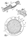
- Figure 1 is a perspective view of a rotary-to-linear actuator which incorporates various of the features of the invention.
- Figure 2 is a cross-sectional view taken along line 2-2 of Figure 1.
-
- Before one embodiment of the invention is explained in detail, it is to be understood that the invention is not limited in its application to the details of the construction and the arrangements of components set forth in the following description or illustrated in the drawings. The invention is capable of other embodiments and of being practiced or being carried out in various ways. Also, it is understood that the phraseology and terminology used herein is for the purpose of description and should not be regarded as limiting.
- Shown in Figure 1 of the drawings is a rotary-to-linear actuator 11 which includes a screw or
shaft 15 and a nut or collar 17 which is received on theshaft 15 and which is displaceable axially of theshaft 15 in response to rotation of theshaft 15. Alternately, if desired, the nut or collar 17 can be displaced axially of the screw orshaft 15 to cause the screw orshaft 15 to rotate. - The
shaft 15 can be fabricated of any suitable rigid material, such as steel. - The
shaft 15 includes a plurality of parallelhelical threads 25 which can be of any desired number more than 8, and which, in the disclosed embodiment, are 24 in number. Thehelical threads 25 are preferably rolled and each have an outwardly convex projectingface 27 separated by an outwardlyconcave valley 29 between the outwardlyconvex faces 27. In the illustrated embodiment, thehelical threads 25 are generated by a straight line extending at a fixed angle often degrees respecting a plane normal to the helical axis. Other fixed angles can also be employed. In the illustrated construction, thethreads 25 provide an axial advance or lead or pitch which is a multiple of the shaft diameter, which multiple is four in the embodiment of the invention shown in the drawings, with the result that the axial advance or pitch or lead is two inches if the shaft diameter is one-half inch. - While other methods can be employed, in the disclosed construction, and as already indicated, the
threads 25 are preferably rolled. Such rolling is more economical to manufacture, as compared, for instance, to machining. In particular, when the number ofthreads 25 is more than eight, rolling is clearly the most effective and economical method for producing thethreads 25 on theshaft 15. - The collar 17 can be fabricated of any suitable low friction material and in the disclosed construction is fabricated of resinous material in the general manner disclosed in U.S. Patent 4,282,764 and includes a like plurality of corresponding spiral threads or
ridges 45 which are received in thethreads 25 and reinforced by successive layers of parallel filaments helically wound over and around the low friction material. The spiral threads orridges 45 include first inner layers (not shown) wound at an angle not greater than the above mentioned fixed angle such that the filaments lie across the outwardly convex projecting faces of the spiral threads orridges 45 and span the grooves. - . Thus, in the specifically disclosed construction, one rotation of the
shaft 15 displaces the collar 17 through an axial distance of about four times the diameter of the shaft. - As more fully explained in U.S. Patent 4,282,764, in the fabrication of the collar, a suitable tubular fabric (not shown) woven from a suitable resinous material, such as polytetrafluoro ethylene, (PTFE) is placed over a mandrel (not shown) with the desired configuration corresponding to the thread form of the
shaft 15. The fabric is then shrunk until the fabric bridges the threads by taking the shortest distance between the threads orridges 45, much like a cord of a circle and not the shape of an arch. Filament wound fiber glass reinforcement is then applied at a steep angle over the woven fabric. Such reinforcement provides structural rigidity and molds the woven fabric to the mandrel with the external thread form and, after curing, provides structural strength to the collar 17. - The invention involves employing multiple starts with a suitable rolled thread form, such as a stub Acme thread form. The more starts the better for the woven (PTFE) fibers which distribute the load over a greater area. In the past, the fibers supporting the woven fabric had to be placed into the thread form, and then the woven fabric was shrunk. With the use of multiple start Acme threads, many starts can be used. Thus, the invention utilizes a low cost metallic mating surface (shaft 15) with multiple starts for better support of the wear element (collar 17). The
shaft 15 can be thread rolled in long lengths. - Thus, because of the use of
multiple threads 25, and the like plurality of threads orridges 45 received in thethreads 25, the load carrying capability of the actuator 11 is greatly increased, while, at the same time, wear is reduced. More specifically, the multiple rolled threads orgrooves 15 greatly reduce manufacturing time and improve the wear life of the nut or collar 17 by increasing the number of engaged threads.
Various of the features are set forth in the following claims.
Claims (7)
- A rotary-to-linear actuator comprising:a rigid shaft (15) having a diameter, and a plurality of parallel helical grooves (25) defining a helical axis, wherein said grooves are formed at a fixed angle relative to a plane normal to said helical axis defining a pitch, each of said grooves having an outwardly projecting convex face (27); anda resinous collar (17) fabricated of low friction material and reinforced by first and successive layers of parallel filaments wound helically around said low friction material, said first layer of parallel filaments being wound at an angle such that the filaments of said first layer lie across said outwardly projecting convex faces (27) of said grooves (25) and forming a plurality of corresponding spiral ridges (45) received in said grooves, whereby one rotation of said shaft (15) displaces said collar through an axial distance equal to said pitch, characterised in that the filaments do not completely fill said grooves.
- A rotary-to-linear actuator in accordance with claim 1, wherein said axial distance is greater than the diameter of the shaft.
- A rotary-to-linear actuator in accordance with claim 1 or claim 2, wherein said plurality of parallel helical grooves (25) provides a lead or pitch equal to a multiple of the diameter of the shaft (15).
- A rotary-to-linear actuator in accordance with any one of the preceding claims, wherein said parallel helical grooves (25) are eight or more in number.
- A rotary-to-linear actuator in accordance with any one of the preceding claims, wherein said first layer of parallel filaments is wound at an angle not greater than said fixed angle.
- A rotary-to-linear actuator in accordance with any one of the preceding claims, wherein said axial distance is a multiple of said diameter.
- A rotary-to-linear actuator in accordance with claim 6, wherein said multiple is four.
Applications Claiming Priority (2)
| Application Number | Priority Date | Filing Date | Title |
|---|---|---|---|
| US09/324,200 US6170346B1 (en) | 1999-06-02 | 1999-06-02 | Rotary-to-linear actuator |
| US324200 | 1999-06-02 |
Publications (3)
| Publication Number | Publication Date |
|---|---|
| EP1058031A2 EP1058031A2 (en) | 2000-12-06 |
| EP1058031A3 EP1058031A3 (en) | 2001-04-04 |
| EP1058031B1 true EP1058031B1 (en) | 2004-08-25 |
Family
ID=23262542
Family Applications (1)
| Application Number | Title | Priority Date | Filing Date |
|---|---|---|---|
| EP00304723A Expired - Lifetime EP1058031B1 (en) | 1999-06-02 | 2000-06-02 | Multiple thread actuator |
Country Status (4)
| Country | Link |
|---|---|
| US (1) | US6170346B1 (en) |
| EP (1) | EP1058031B1 (en) |
| AT (1) | ATE274661T1 (en) |
| DE (1) | DE60013206T2 (en) |
Families Citing this family (2)
| Publication number | Priority date | Publication date | Assignee | Title |
|---|---|---|---|---|
| KR102238238B1 (en) * | 2014-04-07 | 2021-04-09 | 이구스 게엠베하 | Lead screw drive with asymmetrical internal and external thread and corresponding spindle nut |
| DE102014006741B4 (en) * | 2014-05-12 | 2019-07-04 | Thyssenkrupp Presta Ag | CFRP ball nut |
Family Cites Families (16)
| Publication number | Priority date | Publication date | Assignee | Title |
|---|---|---|---|---|
| US3461470A (en) * | 1966-07-07 | 1969-08-19 | Fastron Co | Thread-forming screw and method of making the same |
| US3772720A (en) * | 1970-04-11 | 1973-11-20 | Res Engine Manuf Inc | Method for making a thread forming member |
| US3713932A (en) | 1970-12-15 | 1973-01-30 | Rex Chainbelt Inc | Method of making low friction fabric lined nuts of multiple length construction |
| US3813718A (en) * | 1973-05-24 | 1974-06-04 | M Kamiya | Method of manufacturing roll threaded screws having elasticity |
| US4282764A (en) | 1979-09-17 | 1981-08-11 | Rexnord Inc. | Rotary to linear actuator and method of making the same |
| US4482764A (en) | 1980-11-03 | 1984-11-13 | Basf Aktiengesellschaft | Preparation of diols |
| US4648285A (en) * | 1983-02-14 | 1987-03-10 | Millipore Corporation | Apparatus for converting rotational motion to linear motion |
| US4760635A (en) * | 1984-02-08 | 1988-08-02 | 20Th Century Machine | Method of forming a helical ball screw member |
| DE3502523A1 (en) * | 1985-01-25 | 1986-07-31 | Willibald 8770 Lohr Schachel | Multi-thread spindle drive |
| KR900002192B1 (en) * | 1985-11-22 | 1990-04-04 | 닛봉도꾸슈우기자이가부시끼가이샤 | Screw with groove for self-lock and method and rolling flat die for manufacturing the same |
| CH668726A5 (en) * | 1986-02-03 | 1989-01-31 | Grob Ernst Fa | METHOD AND DEVICE FOR PRODUCING SLOPED GEARS BY COLD FORMING. |
| US4811618A (en) * | 1986-12-12 | 1989-03-14 | Nippon Gear Co., Ltd. | Motion conversion mechanism |
| JPH049475Y2 (en) * | 1987-03-25 | 1992-03-10 | ||
| US4964314A (en) * | 1989-03-13 | 1990-10-23 | Wilkes Donald F | Device for converting rotary motion to linear motion |
| US5080547A (en) * | 1990-03-30 | 1992-01-14 | The B. F. Goodrich Company | Triaxially braided composite nut and bolt |
| US5725344A (en) * | 1996-02-09 | 1998-03-10 | G. W. Lisk Company, Inc. | Positioning device and method of use |
-
1999
- 1999-06-02 US US09/324,200 patent/US6170346B1/en not_active Expired - Lifetime
-
2000
- 2000-06-02 DE DE60013206T patent/DE60013206T2/en not_active Expired - Lifetime
- 2000-06-02 AT AT00304723T patent/ATE274661T1/en active
- 2000-06-02 EP EP00304723A patent/EP1058031B1/en not_active Expired - Lifetime
Also Published As
| Publication number | Publication date |
|---|---|
| US6170346B1 (en) | 2001-01-09 |
| EP1058031A3 (en) | 2001-04-04 |
| DE60013206T2 (en) | 2005-08-11 |
| EP1058031A2 (en) | 2000-12-06 |
| ATE274661T1 (en) | 2004-09-15 |
| DE60013206D1 (en) | 2004-09-30 |
Similar Documents
| Publication | Publication Date | Title |
|---|---|---|
| US5837083A (en) | Method of forming a rigid tubular body | |
| US4282764A (en) | Rotary to linear actuator and method of making the same | |
| US3477474A (en) | Wire reinforced conduit | |
| CA2129636C (en) | Pipe construction | |
| EP3295047B1 (en) | Fibre reinforced polymer matrix composite torque tubes or shafts | |
| US4769967A (en) | Pole of plastic material, in particular for supporting electric power transmission lines | |
| US9566748B2 (en) | FRP composite wrapped grooved-wall lining tubular structure, and method of manufacturing | |
| IL27800A (en) | Composite reinforced plastic pipe and method for fabricating this pipe | |
| US5020783A (en) | Torsional spring | |
| KR20120015316A (en) | Guide roller for wires | |
| EP0325082B1 (en) | Recirculating ball mechanism | |
| EP1058031B1 (en) | Multiple thread actuator | |
| GB2100222A (en) | Filament wound well screen and method and apparatus for making same | |
| GB2280889A (en) | Hollow elongated or tubular bodies and their manufacture | |
| US5352309A (en) | Method for manufacturing pipe bells | |
| US3502527A (en) | Method of making a helically grooved reinforced hose | |
| US6403179B1 (en) | Fiberglass boom and method of making same | |
| FI76739B (en) | FOERSTAERKNINGSSTAONG FOER VULSTEN AV ETT YTTERDAECK. | |
| US4942904A (en) | Hollow section, in particular a tube, of long fibre reinforced plastic | |
| GB2248729A (en) | Flexible reinforced tubes for cable bend strain relief | |
| BR102020019950A2 (en) | composite shaft with an end fitting, and, method of mounting an end fitting to a composite shaft. | |
| US4724669A (en) | Filament-wound cylindrical element for chain | |
| EP3427921B1 (en) | Composite ball screw | |
| DE10327461A1 (en) | Chain wheel, in particular, for a control chain drive of an internal combustion engine comprises an axially extended rim provided with a reinforced elastic layer | |
| JP2002525535A (en) | Synchronous power transmission belt with elastic fabric layer of scaffolding structure |
Legal Events
| Date | Code | Title | Description |
|---|---|---|---|
| PUAI | Public reference made under article 153(3) epc to a published international application that has entered the european phase |
Free format text: ORIGINAL CODE: 0009012 |
|
| AK | Designated contracting states |
Kind code of ref document: A2 Designated state(s): AT DE FR GB IT |
|
| AX | Request for extension of the european patent |
Free format text: AL;LT;LV;MK;RO;SI |
|
| PUAL | Search report despatched |
Free format text: ORIGINAL CODE: 0009013 |
|
| AK | Designated contracting states |
Kind code of ref document: A3 Designated state(s): AT BE CH CY DE DK ES FI FR GB GR IE IT LI LU MC NL PT SE |
|
| AX | Request for extension of the european patent |
Free format text: AL;LT;LV;MK;RO;SI |
|
| 17P | Request for examination filed |
Effective date: 20010925 |
|
| AKX | Designation fees paid |
Free format text: AT DE FR GB IT |
|
| 17Q | First examination report despatched |
Effective date: 20021122 |
|
| GRAP | Despatch of communication of intention to grant a patent |
Free format text: ORIGINAL CODE: EPIDOSNIGR1 |
|
| GRAS | Grant fee paid |
Free format text: ORIGINAL CODE: EPIDOSNIGR3 |
|
| GRAA | (expected) grant |
Free format text: ORIGINAL CODE: 0009210 |
|
| AK | Designated contracting states |
Kind code of ref document: B1 Designated state(s): AT DE FR GB IT |
|
| REG | Reference to a national code |
Ref country code: GB Ref legal event code: FG4D |
|
| REF | Corresponds to: |
Ref document number: 60013206 Country of ref document: DE Date of ref document: 20040930 Kind code of ref document: P |
|
| PLBE | No opposition filed within time limit |
Free format text: ORIGINAL CODE: 0009261 |
|
| STAA | Information on the status of an ep patent application or granted ep patent |
Free format text: STATUS: NO OPPOSITION FILED WITHIN TIME LIMIT |
|
| ET | Fr: translation filed | ||
| 26N | No opposition filed |
Effective date: 20050526 |
|
| REG | Reference to a national code |
Ref country code: FR Ref legal event code: PLFP Year of fee payment: 17 |
|
| REG | Reference to a national code |
Ref country code: FR Ref legal event code: PLFP Year of fee payment: 18 |
|
| REG | Reference to a national code |
Ref country code: FR Ref legal event code: PLFP Year of fee payment: 19 |
|
| PGFP | Annual fee paid to national office [announced via postgrant information from national office to epo] |
Ref country code: IT Payment date: 20190621 Year of fee payment: 20 |
|
| PGFP | Annual fee paid to national office [announced via postgrant information from national office to epo] |
Ref country code: FR Payment date: 20190625 Year of fee payment: 20 |
|
| PGFP | Annual fee paid to national office [announced via postgrant information from national office to epo] |
Ref country code: AT Payment date: 20190521 Year of fee payment: 20 Ref country code: GB Payment date: 20190627 Year of fee payment: 20 Ref country code: DE Payment date: 20190627 Year of fee payment: 20 |
|
| REG | Reference to a national code |
Ref country code: DE Ref legal event code: R071 Ref document number: 60013206 Country of ref document: DE |
|
| REG | Reference to a national code |
Ref country code: GB Ref legal event code: PE20 Expiry date: 20200601 |
|
| REG | Reference to a national code |
Ref country code: AT Ref legal event code: MK07 Ref document number: 274661 Country of ref document: AT Kind code of ref document: T Effective date: 20200602 |
|
| PG25 | Lapsed in a contracting state [announced via postgrant information from national office to epo] |
Ref country code: GB Free format text: LAPSE BECAUSE OF EXPIRATION OF PROTECTION Effective date: 20200601 |