EP1058019B1 - Control for a fluid actuated clutch - Google Patents
Control for a fluid actuated clutch Download PDFInfo
- Publication number
- EP1058019B1 EP1058019B1 EP99110762A EP99110762A EP1058019B1 EP 1058019 B1 EP1058019 B1 EP 1058019B1 EP 99110762 A EP99110762 A EP 99110762A EP 99110762 A EP99110762 A EP 99110762A EP 1058019 B1 EP1058019 B1 EP 1058019B1
- Authority
- EP
- European Patent Office
- Prior art keywords
- clutch
- slip
- control
- pressure
- forward model
- Prior art date
- Legal status (The legal status is an assumption and is not a legal conclusion. Google has not performed a legal analysis and makes no representation as to the accuracy of the status listed.)
- Expired - Lifetime
Links
Images


Classifications
-
- F—MECHANICAL ENGINEERING; LIGHTING; HEATING; WEAPONS; BLASTING
- F16—ENGINEERING ELEMENTS AND UNITS; GENERAL MEASURES FOR PRODUCING AND MAINTAINING EFFECTIVE FUNCTIONING OF MACHINES OR INSTALLATIONS; THERMAL INSULATION IN GENERAL
- F16D—COUPLINGS FOR TRANSMITTING ROTATION; CLUTCHES; BRAKES
- F16D48/00—External control of clutches
- F16D48/06—Control by electric or electronic means, e.g. of fluid pressure
- F16D48/066—Control of fluid pressure, e.g. using an accumulator
-
- B—PERFORMING OPERATIONS; TRANSPORTING
- B60—VEHICLES IN GENERAL
- B60W—CONJOINT CONTROL OF VEHICLE SUB-UNITS OF DIFFERENT TYPE OR DIFFERENT FUNCTION; CONTROL SYSTEMS SPECIALLY ADAPTED FOR HYBRID VEHICLES; ROAD VEHICLE DRIVE CONTROL SYSTEMS FOR PURPOSES NOT RELATED TO THE CONTROL OF A PARTICULAR SUB-UNIT
- B60W50/00—Details of control systems for road vehicle drive control not related to the control of a particular sub-unit, e.g. process diagnostic or vehicle driver interfaces
- B60W2050/0001—Details of the control system
- B60W2050/0002—Automatic control, details of type of controller or control system architecture
- B60W2050/0012—Feedforward or open loop systems
-
- B—PERFORMING OPERATIONS; TRANSPORTING
- B60—VEHICLES IN GENERAL
- B60W—CONJOINT CONTROL OF VEHICLE SUB-UNITS OF DIFFERENT TYPE OR DIFFERENT FUNCTION; CONTROL SYSTEMS SPECIALLY ADAPTED FOR HYBRID VEHICLES; ROAD VEHICLE DRIVE CONTROL SYSTEMS FOR PURPOSES NOT RELATED TO THE CONTROL OF A PARTICULAR SUB-UNIT
- B60W50/00—Details of control systems for road vehicle drive control not related to the control of a particular sub-unit, e.g. process diagnostic or vehicle driver interfaces
- B60W2050/0001—Details of the control system
- B60W2050/0019—Control system elements or transfer functions
- B60W2050/0028—Mathematical models, e.g. for simulation
- B60W2050/0031—Mathematical model of the vehicle
-
- B—PERFORMING OPERATIONS; TRANSPORTING
- B60—VEHICLES IN GENERAL
- B60W—CONJOINT CONTROL OF VEHICLE SUB-UNITS OF DIFFERENT TYPE OR DIFFERENT FUNCTION; CONTROL SYSTEMS SPECIALLY ADAPTED FOR HYBRID VEHICLES; ROAD VEHICLE DRIVE CONTROL SYSTEMS FOR PURPOSES NOT RELATED TO THE CONTROL OF A PARTICULAR SUB-UNIT
- B60W2510/00—Input parameters relating to a particular sub-units
- B60W2510/02—Clutches
- B60W2510/0241—Clutch slip, i.e. difference between input and output speeds
-
- B—PERFORMING OPERATIONS; TRANSPORTING
- B60—VEHICLES IN GENERAL
- B60W—CONJOINT CONTROL OF VEHICLE SUB-UNITS OF DIFFERENT TYPE OR DIFFERENT FUNCTION; CONTROL SYSTEMS SPECIALLY ADAPTED FOR HYBRID VEHICLES; ROAD VEHICLE DRIVE CONTROL SYSTEMS FOR PURPOSES NOT RELATED TO THE CONTROL OF A PARTICULAR SUB-UNIT
- B60W2510/00—Input parameters relating to a particular sub-units
- B60W2510/06—Combustion engines, Gas turbines
- B60W2510/0604—Throttle position
-
- B—PERFORMING OPERATIONS; TRANSPORTING
- B60—VEHICLES IN GENERAL
- B60W—CONJOINT CONTROL OF VEHICLE SUB-UNITS OF DIFFERENT TYPE OR DIFFERENT FUNCTION; CONTROL SYSTEMS SPECIALLY ADAPTED FOR HYBRID VEHICLES; ROAD VEHICLE DRIVE CONTROL SYSTEMS FOR PURPOSES NOT RELATED TO THE CONTROL OF A PARTICULAR SUB-UNIT
- B60W2540/00—Input parameters relating to occupants
- B60W2540/10—Accelerator pedal position
- B60W2540/106—Rate of change
-
- B—PERFORMING OPERATIONS; TRANSPORTING
- B60—VEHICLES IN GENERAL
- B60W—CONJOINT CONTROL OF VEHICLE SUB-UNITS OF DIFFERENT TYPE OR DIFFERENT FUNCTION; CONTROL SYSTEMS SPECIALLY ADAPTED FOR HYBRID VEHICLES; ROAD VEHICLE DRIVE CONTROL SYSTEMS FOR PURPOSES NOT RELATED TO THE CONTROL OF A PARTICULAR SUB-UNIT
- B60W2710/00—Output or target parameters relating to a particular sub-units
- B60W2710/02—Clutches
- B60W2710/025—Clutch slip, i.e. difference between input and output speeds
-
- B—PERFORMING OPERATIONS; TRANSPORTING
- B60—VEHICLES IN GENERAL
- B60W—CONJOINT CONTROL OF VEHICLE SUB-UNITS OF DIFFERENT TYPE OR DIFFERENT FUNCTION; CONTROL SYSTEMS SPECIALLY ADAPTED FOR HYBRID VEHICLES; ROAD VEHICLE DRIVE CONTROL SYSTEMS FOR PURPOSES NOT RELATED TO THE CONTROL OF A PARTICULAR SUB-UNIT
- B60W2710/00—Output or target parameters relating to a particular sub-units
- B60W2710/02—Clutches
- B60W2710/027—Clutch torque
-
- B—PERFORMING OPERATIONS; TRANSPORTING
- B60—VEHICLES IN GENERAL
- B60W—CONJOINT CONTROL OF VEHICLE SUB-UNITS OF DIFFERENT TYPE OR DIFFERENT FUNCTION; CONTROL SYSTEMS SPECIALLY ADAPTED FOR HYBRID VEHICLES; ROAD VEHICLE DRIVE CONTROL SYSTEMS FOR PURPOSES NOT RELATED TO THE CONTROL OF A PARTICULAR SUB-UNIT
- B60W30/00—Purposes of road vehicle drive control systems not related to the control of a particular sub-unit, e.g. of systems using conjoint control of vehicle sub-units, or advanced driver assistance systems for ensuring comfort, stability and safety or drive control systems for propelling or retarding the vehicle
- B60W30/18—Propelling the vehicle
- B60W30/20—Reducing vibrations in the driveline
-
- F—MECHANICAL ENGINEERING; LIGHTING; HEATING; WEAPONS; BLASTING
- F16—ENGINEERING ELEMENTS AND UNITS; GENERAL MEASURES FOR PRODUCING AND MAINTAINING EFFECTIVE FUNCTIONING OF MACHINES OR INSTALLATIONS; THERMAL INSULATION IN GENERAL
- F16D—COUPLINGS FOR TRANSMITTING ROTATION; CLUTCHES; BRAKES
- F16D2500/00—External control of clutches by electric or electronic means
- F16D2500/30—Signal inputs
- F16D2500/304—Signal inputs from the clutch
- F16D2500/30404—Clutch temperature
-
- F—MECHANICAL ENGINEERING; LIGHTING; HEATING; WEAPONS; BLASTING
- F16—ENGINEERING ELEMENTS AND UNITS; GENERAL MEASURES FOR PRODUCING AND MAINTAINING EFFECTIVE FUNCTIONING OF MACHINES OR INSTALLATIONS; THERMAL INSULATION IN GENERAL
- F16D—COUPLINGS FOR TRANSMITTING ROTATION; CLUTCHES; BRAKES
- F16D2500/00—External control of clutches by electric or electronic means
- F16D2500/30—Signal inputs
- F16D2500/306—Signal inputs from the engine
- F16D2500/3067—Speed of the engine
-
- F—MECHANICAL ENGINEERING; LIGHTING; HEATING; WEAPONS; BLASTING
- F16—ENGINEERING ELEMENTS AND UNITS; GENERAL MEASURES FOR PRODUCING AND MAINTAINING EFFECTIVE FUNCTIONING OF MACHINES OR INSTALLATIONS; THERMAL INSULATION IN GENERAL
- F16D—COUPLINGS FOR TRANSMITTING ROTATION; CLUTCHES; BRAKES
- F16D2500/00—External control of clutches by electric or electronic means
- F16D2500/30—Signal inputs
- F16D2500/308—Signal inputs from the transmission
- F16D2500/3081—Signal inputs from the transmission from the input shaft
- F16D2500/30816—Speed of the input shaft
-
- F—MECHANICAL ENGINEERING; LIGHTING; HEATING; WEAPONS; BLASTING
- F16—ENGINEERING ELEMENTS AND UNITS; GENERAL MEASURES FOR PRODUCING AND MAINTAINING EFFECTIVE FUNCTIONING OF MACHINES OR INSTALLATIONS; THERMAL INSULATION IN GENERAL
- F16D—COUPLINGS FOR TRANSMITTING ROTATION; CLUTCHES; BRAKES
- F16D2500/00—External control of clutches by electric or electronic means
- F16D2500/30—Signal inputs
- F16D2500/314—Signal inputs from the user
- F16D2500/31406—Signal inputs from the user input from pedals
- F16D2500/3144—Accelerator pedal position
-
- F—MECHANICAL ENGINEERING; LIGHTING; HEATING; WEAPONS; BLASTING
- F16—ENGINEERING ELEMENTS AND UNITS; GENERAL MEASURES FOR PRODUCING AND MAINTAINING EFFECTIVE FUNCTIONING OF MACHINES OR INSTALLATIONS; THERMAL INSULATION IN GENERAL
- F16D—COUPLINGS FOR TRANSMITTING ROTATION; CLUTCHES; BRAKES
- F16D2500/00—External control of clutches by electric or electronic means
- F16D2500/50—Problem to be solved by the control system
- F16D2500/52—General
- F16D2500/525—Improve response of control system
-
- F—MECHANICAL ENGINEERING; LIGHTING; HEATING; WEAPONS; BLASTING
- F16—ENGINEERING ELEMENTS AND UNITS; GENERAL MEASURES FOR PRODUCING AND MAINTAINING EFFECTIVE FUNCTIONING OF MACHINES OR INSTALLATIONS; THERMAL INSULATION IN GENERAL
- F16D—COUPLINGS FOR TRANSMITTING ROTATION; CLUTCHES; BRAKES
- F16D2500/00—External control of clutches by electric or electronic means
- F16D2500/70—Details about the implementation of the control system
- F16D2500/704—Output parameters from the control unit; Target parameters to be controlled
- F16D2500/70402—Actuator parameters
- F16D2500/70406—Pressure
-
- F—MECHANICAL ENGINEERING; LIGHTING; HEATING; WEAPONS; BLASTING
- F16—ENGINEERING ELEMENTS AND UNITS; GENERAL MEASURES FOR PRODUCING AND MAINTAINING EFFECTIVE FUNCTIONING OF MACHINES OR INSTALLATIONS; THERMAL INSULATION IN GENERAL
- F16D—COUPLINGS FOR TRANSMITTING ROTATION; CLUTCHES; BRAKES
- F16D2500/00—External control of clutches by electric or electronic means
- F16D2500/70—Details about the implementation of the control system
- F16D2500/704—Output parameters from the control unit; Target parameters to be controlled
- F16D2500/70422—Clutch parameters
- F16D2500/70426—Clutch slip
-
- F—MECHANICAL ENGINEERING; LIGHTING; HEATING; WEAPONS; BLASTING
- F16—ENGINEERING ELEMENTS AND UNITS; GENERAL MEASURES FOR PRODUCING AND MAINTAINING EFFECTIVE FUNCTIONING OF MACHINES OR INSTALLATIONS; THERMAL INSULATION IN GENERAL
- F16D—COUPLINGS FOR TRANSMITTING ROTATION; CLUTCHES; BRAKES
- F16D2500/00—External control of clutches by electric or electronic means
- F16D2500/70—Details about the implementation of the control system
- F16D2500/706—Strategy of control
- F16D2500/70631—Feed-forward
-
- F—MECHANICAL ENGINEERING; LIGHTING; HEATING; WEAPONS; BLASTING
- F16—ENGINEERING ELEMENTS AND UNITS; GENERAL MEASURES FOR PRODUCING AND MAINTAINING EFFECTIVE FUNCTIONING OF MACHINES OR INSTALLATIONS; THERMAL INSULATION IN GENERAL
- F16D—COUPLINGS FOR TRANSMITTING ROTATION; CLUTCHES; BRAKES
- F16D2500/00—External control of clutches by electric or electronic means
- F16D2500/70—Details about the implementation of the control system
- F16D2500/706—Strategy of control
- F16D2500/70652—Open loop
Definitions
- the invention relates to a method for automatic Control a clutch that has a torque of one Transfers engine to a transmission, according to the generic term of Claim 1.
- DE 39 18 254 A1 describes a method for prevention of load changes due to abrupt changes in the Accelerator pedal position known, in which the torque of the Transfer clutch smoothly during normal driving and in the case of sudden load changes artificial clutch slip is generated, which then is reduced to zero again.
- the generic US 5 527 238 describes a control method for the Bypass clutch of a torque converter, with improvement slip control parallel to a PID controller Feed-forward model is used.
- a method for regulating clutch slip also shows US 5 002 170, but without a feed-forward model would be used.
- the present invention has the object based on increasing driving comfort.
- the method includes that in a clutch that the Transmits torque in normal driving operation without slip sudden load changes an artificial clutch slip generated and then gradually to zero again is reduced.
- Tip-ins i.e. when the Accelerator pedal or if the accelerator pedal is suddenly released, Powertrain blows from the inevitable Avoid play in the drive train elements.
- the blows are soft intercepted, thereby depriving the driver of his perception become.
- the sudden load changes are preferred due to a quickly change the position of a power control of the engine recognized.
- an artificial clutch slip even at very low Vehicle speeds are activated, for example when coasting the engine to stall the engine to prevent without a complete at this stage Disengaging is required.
- the clutch with the help of a Inverse feed-forward model controlled that the by means of a Actuator on the clutch pressure to be applied depending on a desired clutch slip certainly.
- the inverse feed-forward model can be optional work with or without feedback, so that ever Depending on the operating mode, a pure control or a slip or speed control are possible.
- the Coupling pressure across the inverse feed-forward model during of slip-free normal driving operation (i.e. after the starting process) set to a pressure that is at the minimum pressure for freedom from slip plus a safety factor lies.
- the feed-forward model works during this Normal driving operation preferred in a feedback-free (Open Loop) mode.
- the security factor is measured so tightly that the occurrence of slip in normal driving is still avoided. Because not the full Clutch pressure is applied, are internal to the clutch Minimized losses.
- the clutch is still through this Measure the weakest link in the drive chain so that heavy blows from the road to the powertrain The clutch slips, which protects the gearbox.
- the friction value is particularly preferably included in the feed-forward model the clutch, and the artificial clutch slip is generated by increasing the coefficient of friction. hereby a clutch with a better grip than existing is simulated, so that in reality - there is no feedback control occurs - a slip results.
- the coefficient of friction is to generate an artificial hatch, i.e. for the light Opening the clutch, a particularly suitable size, because on this way with little effort and very short response times starting from a fully closed clutch a defined slip can be brought about.
- the task with a generic Clutch control is solved in that they facilities and Has controller for performing these process steps.
- the embodiment shown in Figure 1 has one Hardware part 1 and a software part 2.
- To the hardware part 1 include the transmission 3, the clutch 4, e.g. a hydraulic Wet clutch with return spring, also a control valve 5, e.g. a proportional valve and a variable one Control magnet 6.
- a certain hydraulic pressure on the clutch 4 which in turn causes the transmission or the clutch slip of the transmission 3 is affected becomes.
- the transmission is based on the engine speed before Clutch 4 and the primary speed or the transmission input speed determined behind the clutch 4. The difference from These two speeds determine the current clutch slip.
- This clutch slip represents a possible actual value for a clutch control.
- the slip control is the upper control block 7 of the software part in FIG. 1 2.
- the lower control block 8 provides engine speed control represents.
- the slip control 7 has a PID controller 9, which the Gear 3 both the engine speed 10 and the transmission input speed 11 is fed, this feed can be interrupted with a switch 12. From the difference between engine speed 10 and transmission input speed 11 the current clutch slip is calculated.
- the PID controller 9 is also a setpoint 13 for a Clutch slip rate or a clutch slip setpoint fed, which also directly an inverse feed-forward model 14 are fed to the clutch control. Also these leads can be interrupted by switches 15 and 16 become.
- the hydraulic pressure is between the control valve 5 and the clutch 4 queried, and a corresponding signal 17th is also passed to the inverse feed forward model 14.
- a corresponding signal 17th is also passed to the inverse feed forward model 14.
- the inverse feed-forward model 14 can still more Control variables 18 received, the different clutch states represent.
- the software part 2 also contains a real-time torque calculation 19, in which a number of suitable parameters 20 for the engine operating condition, e.g. Ignition timing and Air / fuel ratio.
- the real-time engine torque is also the inverse for the slip control 7 Feed-forward model 14 fed.
- the engine speed control 8 also has a PID controller 21 on.
- the engine speed 22 is supplied to it by the transmission 3, the corresponding line through a switch 23 can be interrupted.
- the PID controller 21 will also a target engine speed 24 is supplied.
- the initial size of the PID controller 8 is a signal for an engine torque 25.
- the calculated real-time torque is also used to control the engine speed 8 forwarded.
- the lines from the PID controller 21 and from the real-time torque calculation 19 to the inverse feed-forward model can be interrupted with two switches 27 and 27a.
- the inverse feed forward model 14 determines from it supplied by the slip or engine speed control 7, 8 Data a target current 28, which it the variable Control magnet 6 supplies. Actuated due to the target current 28 the control magnet 6, the control valve 5 to a predetermined To generate hydraulic pressure on the clutch 4.
- the inverse feed-forward model 14 used is a further development the feed-forward strategy. With the feed-forward strategy a certain proportion of the target size becomes direct given on the manipulated variable. The remaining portion of the The setpoint runs through a conventional control loop. However, this only works satisfactorily if the one given directly to the controller output Input size with the right size and the right one Direction works. This requires impact the actual variable change to the manipulated variable as precisely as possible to know in advance.
- the inverse feed-forward model is used for this 14 of the clutch control shown.
- the inverse Feed-forward model 14 calculates the characteristic of the control magnet 6, the control valve 5, the hydraulics 29 and the Clutch 4 reverse, i.e. it simulates the transfer function the controlled system in an inverse manner. Along with the controlled system thus results in a transfer function of almost one. Due to model inaccuracies, for example an unconsidered clutch aging however, a feedback scheme continues in certain Operating modes necessary, but only errors are corrected and no longer the entire target size.
- FIG. 2 shows the inverse feed-forward model 14 in more detail. It includes blocks I to V, each different physical aspects of the clutch are simulated.
- Block II contains the clutch model in which the target torque 31 also entered bypassing block I directly can be.
- Other input variables are a control variable 32 for the brake-away control, which is below is a control variable 33 for the ramp of the Torque control with clutch closed (will also explained in more detail below) and a tax variable 34 for pump losses.
- the latter tax variable 34 is the Block II fed from block III.
- block II the required Coupling pressure calculated at a desired torque. The geometry of the coupling and the static and dynamic friction coefficient of the clutch taken into account.
- So-called pump losses 34 are calculated in block III are transmitted as an output variable to block II.
- Pump losses are among others speed and temperature dependent Fluctuations in clutch fluid flow and fluctuations taken into account in the fluid supply system, which for the Generation of a desired clutch pressure required Influence valve position and therefore in the feed-forward model are to be considered.
- Block IV contains a control valve model.
- Block IV receives from Block II is the input variable to be set by the control valve Clutch pressure 35, i.e. the one to be set on the clutch Hydraulic pressure.
- Other input variables are a Signal 36 from an optional pressure sensor and signal 37 for the open-loop pressure ramp with the clutch open (will continue explained in more detail below).
- Block IV is essentially implements a table or function that the to be controlled Position of the valve for a desired clutch pressure contains. This essentially depends on the geometry of the valve from.
- Block V contains the model for the variable control magnet 6 and receives a control signal as an input variable from block IV 38 for the hydraulic pressure to be set.
- Initial size of the Blocks V is the required target current to be applied 28. In this block thus becomes the nonlinear characteristic of the variable Control magnet compensated.
- State II represents a creep mode without torque transmission (Low creep), i.e. the vehicle is stationary. At a Gear lever change from P or also from N (idle) to D target the creep mode does not start with too much delay. Due to the finite length of the hydraulic line 29 from Control valve 5 to clutch 4 and due to the ventilation this hydraulic line 29 with a longer disengagement time, A hydraulic oil column must first be used to effect clutch pressure be built up, resulting in said delay leads.
- the courses of five are characteristic in FIG Sizes shown over time. To these characteristic Sizes include clutch pressure A, timer B, a calculated clutch torque C on the control solenoids D applied target current 0 and the position of the gear selector lever E.
- the gear selector lever E is located between the times t0 and t1 to N, the target current D is for closing the control valve 5 large, the calculated or target clutch torque C. 0, timer B is at 0 and clutch pressure A is also to 0.
- gear selector lever E is shifted from N to D. to reduce the delay due to construction the hydraulic oil column according to the invention for a so-called Blip-Time 39 between t1 and t2 a high arithmetic Coupling torque 40 given to the clutch control.
- the clutch control leaves the clutch pressure A in a pure open loop control can rise very high.
- This is purely timer-controlled as long (in the example shown up to time t2) until after experience has built up sufficient pressure without the clutch 4 engages to prevent the engine stalling.
- the Blip-Time 39 or the set duration of the timer depends on the temperature, to the temperature dependent viscosity of the Hydraulic oil to be considered.
- Creep high creep, condition IV
- This Creeping can be done open-loop, i.e. with one certain transmission factor so that the vehicle is dependent of gradient, temperature, etc. at different speeds creeps.
- This option is based on a given Clutch pressure regulated. But it is also an engine speed control 8 closed-loop according to Figure 1 possible, so that Vehicle always crawls at the same speed. It is also conceivable that the driver is between regulated and unregulated creep can choose. It is also conceivable that the driver Crawl can completely turn off via a switch. in the State IV will be blocks II to V of the inverse feed-forward model 14 executed.
- the state X represents a feature that the driving comfort in increased in a special way.
- Starting from state X only can be activated by state IX in two ways: once by a so-called "tip in", i.e. an abrupt Depress the accelerator pedal or release suddenly of the accelerator pedal, causing rapid changes in throttle position and secondly due to very low vehicle speeds, where the fully closed Clutch choking the engine would be feared as for example when rolling out the vehicle.
- tip in i.e. an abrupt Depress the accelerator pedal or release suddenly of the accelerator pedal, causing rapid changes in throttle position and secondly due to very low vehicle speeds, where the fully closed Clutch choking the engine would be feared as for example when rolling out the vehicle.
- To beat in To prevent the drivetrain or stalling is used in this Condition creates an artificial clutch slip (so-called. Brake-away control). This can be done through special regular measures are generated by the clutch 4 a little is opened.
- state XI can still be approached be below a given vehicle speed is activated.
- the clutch pressure is in state XI not immediately moved to zero to close the clutch open, but there is a defined ramp open-loop of at an initially higher set pressure to produce a reproducible feeling when disengaging. Therefor only blocks IV and V of the inverse feed-forward model 14 used.
Description
Die Erfindung bezieht sich auf ein Verfahren zum automatischen
Steuern einer Kupplung, die ein Drehmoment von einem
Motor auf ein Getriebe überträgt, nach dem Oberbegriff von
Anspruch 1.The invention relates to a method for automatic
Control a clutch that has a torque of one
Transfers engine to a transmission, according to the generic term of
Aus der US 5 553 694 ist eine automatische Kupplungssteuerung für Kraftfahrzeuge bekannt, bei der der Kupplungsschlupf auf einen gewünschten Wert einstellbar ist. Der Kupplungsschlupf bestimmt sich aus der Differenz der Motordrehzahl vor der Kupplung und der Getriebeeingangsdrehzahl hinter der Kupplung. Zur Reduzierung der Verzögerung in der Steuerung bzw. in der Regelung wird eine sogenannte Feed-Forward-Strategie angewendet, bei der ein gewisser Anteil der Sollgröße direkt auf die Stellgröße gegeben wird und der restliche Anteil über einen konventionellen Regelkreis läuft. Der hiermit erreichbare Fahrkomfort ist allerdings noch nicht zufriedenstellend, da während der Fahrt, beispielsweise bei einem abrupten Niederdrücken bzw. Loslassen des Gaspedals, Schläge im Antriebsstrang auftreten können.An automatic clutch control is known from US Pat. No. 5,553,694 known for motor vehicles in which the clutch slip can be set to a desired value. The Clutch slip is determined from the difference in engine speed before the clutch and the transmission input speed behind the clutch. To reduce the delay in a so-called Feed-forward strategy applied in which a certain proportion the setpoint is given directly to the manipulated variable and the remainder via a conventional control loop running. However, the driving comfort that can be achieved with this is not yet satisfactory, because while driving, for example in the case of an abrupt depression or release of the accelerator pedal, impacts in the drive train can occur.
Aus der DE 39 18 254 A1 ist ein Verfahren zur Verhinderung von Lastwechselschlägen in Folge abrupter Veränderungen der Gaspedalstellung bekannt, bei welchem das Drehmoment von der Kupplung während des Normalfahrbetriebs schlupffrei übertragen wird und bei dem im Falle plötzlicher Laständerungen ein künstlicher Kupplungsschlupf erzeugt wird, welcher anschließend wieder auf Null verringert wird. DE 39 18 254 A1 describes a method for prevention of load changes due to abrupt changes in the Accelerator pedal position known, in which the torque of the Transfer clutch smoothly during normal driving and in the case of sudden load changes artificial clutch slip is generated, which then is reduced to zero again.
Die gattungsgemäße US 5 527 238 beschreibt ein Regelungsverfahren für die Bypass-Kupplung eines Drehmomentwandlers, wobei zur Verbesserung der Schlupfregelung parallel zu einem PID-Regler ein Feed-Forward-Modell eingesetzt wird.The generic US 5 527 238 describes a control method for the Bypass clutch of a torque converter, with improvement slip control parallel to a PID controller Feed-forward model is used.
Ein Verfahren zur Regelung des Kupplungsschlupfes zeigt auch die US 5 002 170, ohne dass jedoch hierbei ein Feed-Forward-Modell zum Einsatz käme.A method for regulating clutch slip also shows US 5 002 170, but without a feed-forward model would be used.
Demgegenüber liegt der vorliegenden Erfindung die Aufgabe zugrunde, den Fahrkomfort zu erhöhen.In contrast, the present invention has the object based on increasing driving comfort.
Diese Aufgabe wird durch ein Verfahren mit den Merkmalen des
Anspruchs 1 gelöst.This task is accomplished by a process with the characteristics of
Das Verfahren beinhaltet, daß bei einer Kupplung, die das Drehmoment im Normalfahrbetrieb Schlupffrei überträgt, bei plötzlichen Laständerungen ein künstlicher Kupplungsschlupf erzeugt und dieser anschließend allmählich wieder auf Null verringert wird. Hierdurch werden bei sogenannten Tip-Ins, also bei einem abrupten Niederdrücken des Gaspedals bzw. bei einem plötzlichen Loslassen des Gaspedals, Schläge im Antriebsstrang durch das unvermeidliche Spiel in den Antriebsstrangelementen vermieden. Durch den künstlich kurzzeitig erzeugten Schlupf in der Kupplung werden die Schläge im Unterschied zum Stand der Technik weich abgefangen, wodurch diese der Wahrnehmung des Fahrers entzogen werden.The method includes that in a clutch that the Transmits torque in normal driving operation without slip sudden load changes an artificial clutch slip generated and then gradually to zero again is reduced. As a result, so-called Tip-ins, i.e. when the Accelerator pedal or if the accelerator pedal is suddenly released, Powertrain blows from the inevitable Avoid play in the drive train elements. By the briefly generated slip in the clutch in contrast to the prior art, the blows are soft intercepted, thereby depriving the driver of his perception become.
Die plötzlichen Laständerungen werden bevorzugt aufgrund einer schnellen Änderung der Stellung eines Leistungssteuerelements des Motors erkannt.The sudden load changes are preferred due to a quickly change the position of a power control of the engine recognized.
Zusätzlich kann in einer bevorzugten Ausführungsform der Erfindung ein künstlicher Kupplungsschlupf auch bei sehr niedrigen Fahrzeuggeschwindigkeiten aktiviert werden, beispielsweise beim Ausrollen des Motors, um ein Abwürgen des Motors zu verhindern, ohne daß schon in diesem Stadium ein vollständiges Auskuppeln erforderlich ist.In addition, in a preferred embodiment of the invention an artificial clutch slip even at very low Vehicle speeds are activated, for example when coasting the engine to stall the engine to prevent without a complete at this stage Disengaging is required.
Im Rahmen der Erfindung wird die Kupplung mit Hilfe eines inversen Feed-Forward-Modells gesteuert, das den mittels eines Stellgliedes auf die Kupplung aufzubringenden Kupplungsdruck in Abhängigkeit von einem gewünschten Kupplungsschlupf bestimmt. Das inverse Feed-Forward-Modell kann dabei wahlweise mit oder ohne Rückkopplungsanteil arbeiten, so daß je nach Betriebsmodus eine reine Steuerung oder eine Schlupf- bzw. Drehzahlregelung möglich sind.In the context of the invention, the clutch with the help of a Inverse feed-forward model controlled that the by means of a Actuator on the clutch pressure to be applied depending on a desired clutch slip certainly. The inverse feed-forward model can be optional work with or without feedback, so that ever Depending on the operating mode, a pure control or a slip or speed control are possible.
In einer bevorzugten Ausgestaltung der Erfindung wird der Kupplungsdruck über das inverse Feed-Forward-Modell während des schlupffreien Normalfahrbetriebes (d.h. nach dem Anfahrvorgang) auf einen Druck eingestellt, der bei dem Minimaldruck für Schlupffreiheit zuzüglich eines Sicherheitsfaktors liegt. Das Feed-Forward-Modell arbeitet während dieses Normalfahrbetriebes bevorzugt in einem rückkopplungslosen Modus (Open Loop). Der Sicherheitsfaktor wird so knapp bemessen, daß das Auftreten eines Schlupfes im Normalfahrbetrieb noch vermieden wird. Dadurch, daß nicht der volle Kupplungsdruck aufgebracht wird, werden kupplungsinterne Verluste minimiert. Die Kupplung ist weiterhin durch diese Maßnahme das schwächste Glied in der Antriebskette, so daß schwere Schläge von der Straße auf den Antriebsstrang zum Durchrutschen der Kupplung führen, was das Getriebe schützt. Leichtere Schläge, wie sie bei Tip-Ins auftreten, und im Rahmen der Erfindung abgefangen werden sollen, werden bei der im Normalfahrbetrieb vorgesehen Kupplungsstellung noch nicht abgefangen. Jedoch begünstigt der reduzierte Kupplungsdruck eine besonders schnelle Reaktion auf plötzliche Laständerungen im Rahmen der Erfindung, da geringere Druckänderungen verglichen mit einer mit vollem Druck beaufschlagten Kupplung auszuführen sind.In a preferred embodiment of the invention, the Coupling pressure across the inverse feed-forward model during of slip-free normal driving operation (i.e. after the starting process) set to a pressure that is at the minimum pressure for freedom from slip plus a safety factor lies. The feed-forward model works during this Normal driving operation preferred in a feedback-free (Open Loop) mode. The security factor is measured so tightly that the occurrence of slip in normal driving is still avoided. Because not the full Clutch pressure is applied, are internal to the clutch Minimized losses. The clutch is still through this Measure the weakest link in the drive chain so that heavy blows from the road to the powertrain The clutch slips, which protects the gearbox. Lighter blows, as they occur with tip-ins, and in Within the scope of the invention are to be intercepted at the clutch position provided in normal driving mode not intercepted. However, the reduced clutch pressure favors a particularly quick response to sudden Load changes in the context of the invention, since less Pressure changes compared to one at full pressure Coupling must be carried out.
Besonders bevorzugt geht in das Feed-Forward-Modell der Reibungswert der Kupplung ein, und der künstliche Kupplungsschlupf wird durch Erhöhen des Reibungswertes erzeugt. Hierdurch wird eine griffigere Kupplung als vorhanden simuliert, so daß sich in der Realität - da keine Rückkopplungsregelung erfolgt - ein Schlupf ergibt. Der Reibungswert ist zum Erzeugen eines künstlichen Schlupfes, d.h. für das leichte Öffnen der Kupplung, eine besonders geeignete Größe, da auf diese Weise mit geringem Aufwand und sehr kurzen Ansprechzeiten ausgehend von einer vollständig geschlossenen Kupplung ein definierter Schlupf bewirkt werden kann.The friction value is particularly preferably included in the feed-forward model the clutch, and the artificial clutch slip is generated by increasing the coefficient of friction. hereby a clutch with a better grip than existing is simulated, so that in reality - there is no feedback control occurs - a slip results. The coefficient of friction is to generate an artificial hatch, i.e. for the light Opening the clutch, a particularly suitable size, because on this way with little effort and very short response times starting from a fully closed clutch a defined slip can be brought about.
Bevorzugt wird nach Erzeugung des künstlichen Kupplungsschlupfes, durch den Schläge im Antriebsstrang abgefangen werden, über das inverse Feed-Forward-Modell eine Rückkopplungsregelung mit dem Schlupfsollwert "0" durchgeführt, bis dieser Sollwert erreicht ist. Dieser Übergang vom rückkopplungslosen in einen Regelmodus mit Rückkopplung kann nach einer vorgegebenen kurzen Zeit oder sofort nach Änderung des Reibungswertes ausgeführt werden. Bevorzugt verbleibt der Reibungswert der Kupplung bis zum Abschluß der Schlupfregelung - wie vorstehend beschrieben - bei seinem künstlich modifizierten Wert und wird erst nach Erreichen der Schlupffreiheit wieder auf den "richtigen" Wert gesetzt, so daß bis zum Erreichen des Schlupfes "0" ein sanfter Übergang in den Normalfahrbetrieb ohne Unstetigkeiten erreicht wird.After generation of the artificial clutch slip, preference is given to intercepted by the blows in the drive train a feedback control via the inverse feed-forward model carried out with the slip setpoint "0" until this setpoint has been reached. This transition from the feedbackless can go into a control mode with feedback a predetermined short time or immediately after changing the Friction coefficient are executed. The remains preferably Friction value of the clutch until the slip control is completed - As described above - in his artificially modified Value and will only become after freedom from slip set back to the "correct" value so that until to reach the slip "0" a smooth transition into the Normal driving operation is achieved without discontinuities.
Erfindungsgemäß wird die Aufgabe bei einer gattungsgemäßen Kupplungssteuerung dadurch gelöst, daß sie Einrichtungen und Regler zur Durchführung dieser Verfahrensschritte aufweist.According to the invention, the task with a generic Clutch control is solved in that they facilities and Has controller for performing these process steps.
Die Erfindung wird nachfolgend anhand der Zeichnungen beispielshalber noch näher erläutert. Es zeigen:
Figur 1- in einer schematischen Darstellung eine erfindungsgemäße Kupplungssteuerung,
Figur 2- ein Blockdiagramm eines inversen Feed-Forward-Modells,
das in der Kupplungssteuerung aus
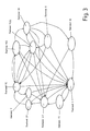
Figur 1 eingesetzt wird, Figur 3- in einer schematischen Darstellung ein Zustandsschaubild einer erfindungsgemäßen Kupplungssteuerung, und
Figur 4- ein Schaubild für den Übergang vom Zustand I zum
Zustand II in
Figur 3 unter Ausbildung einer Blip-Time.
- Figure 1
- a clutch control according to the invention in a schematic representation,
- Figure 2
- 2 shows a block diagram of an inverse feed-forward model which is used in the clutch control from FIG. 1,
- Figure 3
- in a schematic representation, a state diagram of a clutch control according to the invention, and
- Figure 4
- a diagram for the transition from state I to state II in Figure 3 with formation of a blip time.
Als Ausführungsbeispiel für das erfindungsgemäße Verfahren und die erfindungsgemäße Kupplungssteuerung wird deren Anwendung auf eine hydraulische Naßkupplung, die im Antriebsstrang eines Kraftfahrzeuges vor einem stufenlosen automatischen Getriebe angeordnet ist, beschrieben. Es ist jedoch auch eine Anwendung für Schaltgetriebe denkbar.As an embodiment for the method according to the invention and the clutch control according to the invention becomes its application on a hydraulic wet clutch in the drive train of a motor vehicle in front of a continuously variable automatic Gear is arranged is described. However, it is an application for manual transmissions is also conceivable.
Das in Figur 1 dargestellte Ausführungsbeispiel weist einen
Hardware-Teil 1 und einen Software-Teil 2 auf. Zum Hardware-Teil
1 gehören das Getriebe 3, die Kupplung 4, z.B. eine hydraulische
Naßkupplung mit Rückstellfeder, ferner ein Steuerventil
5, z.B. ein Proportionalventil, sowie ein variabler
Steuermagnet 6. Abhängig von einem an den Steuermagneten 6
angelegten Sollstrom stellt sich ein bestimmter Hydraulikdruck
auf die Kupplung 4 ein, wodurch wiederum die Transmission
bzw. der Kupplungsschlupf des Getriebes 3 beeinflußt
wird. Die Transmission wird aus der Motordrehzahl vor der
Kupplung 4 und der Primärdrehzahl bzw. der Getriebeeingangsdrehzahl
hinter der Kupplung 4 bestimmt. Die Differenz aus
diesen beiden Drehzahlen bestimmt den aktuellen Kupplungsschlupf.
Dieser Kupplungsschlupf stellt eine mögliche Istwertgröße
für eine Kupplungsregelung dar. Die Schlupfregelung
ist der in Figur 1 obere Regelblock 7 des Software-Teils
2. Der untere Regelblock 8 stellt eine Motordrehzahlregelung
dar.The embodiment shown in Figure 1 has one
Die Schlupfregelung 7 weist einen PID-Regler 9 auf, dem vom
Getriebe 3 sowohl die Motordrehzahl 10 als auch die Getriebeeingangsdrehzahl
11 zugeführt wird, wobei diese Zuführung
mit einem Schalter 12 unterbrochen werden kann. Aus der Differenz
zwischen der Motordrehzahl 10 und der Getriebeeingangsdrehzahl
11 wird der aktuelle Kupplungsschlupf errechnet.
Dem PID-Regler 9 wird ebenfalls ein Sollwert 13 für eine
Kupplungsschlupfrate oder ein Kupplungsschlupf-Sollwert
zugeführt, die auch direkt einem inversen Feed-Forward-Modell
14 der Kupplungssteuerung zugeleitet werden. Auch
diese Zuleitungen können durch Schalter 15 und 16 unterbrochen
werden.The
Zwischen dem Steuerventil 5 und der Kupplung 4 wird der Hydraulikdruck
abgefragt, und ein entsprechendes Signal 17
wird ebenfalls zu dem inversen Feed-Forward-Modell 14 geleitet.
In das inverse Feed-Forward-Modell 14 können noch weitere
Steuergrößen 18 eingehen, die verschiedene Kupplungszustände
darstellen.The hydraulic pressure is between the
Der Software-Teil 2 enthält auch eine Echtzeit-Drehmomentberechnung
19, in die eine Reihe von geeigneten Kenngrößen
20 für den Motorbetriebszustand, wie z.B. Zündzeitpunkt und
Luft/Kraftstoff-Verhältnis, eingehen. Das Echtzeit-Motordrehmoment
wird für die Schlupfregelung 7 ebenfalls dem inversen
Feed-Forward-Modell 14 zugeführt.The
Die Motordrehzahlregelung 8 weist ebenfalls einen PID-Regler
21 auf. Diesem wird vom Getriebe 3 die Motordrehzahl 22 zugeführt,
wobei die entsprechende Leitung durch einen Schalter
23 unterbrochen werden kann. Dem PID-Regler 21 wird auch
eine Soll-Motordrehzahl 24 zugeführt. Die Ausgangsgröße des
PID-Reglers 8 ist ein Signal für ein Motordrehmoment 25.The
Das berechnete Echtzeit-Drehmoment wird auch der Motordrehzahlregelung
8 zugeleitet. Aus dem Echtzeit-Drehmoment und
dem vom PID-Regler 21 gelieferten Drehmoment 25 wird ein
Solldrehmoment 26 ermittelt, das für die Motordrehzahlregelung
8 dem inversen Feed-Forward-Modell 14 zugeführt wird.
Die Leitungen vom PID-Regler 21 und von der Echtzeit-Drehmomentberechnung
19 zum inversen Feed-Forward-Modell
können mit zwei Schaltern 27 und 27a unterbrochen werden.The calculated real-time torque is also used to control the
Das inverse Feed-Forward-Modell 14 ermittelt aus den ihm
durch die Schlupf- oder die Motordrehzahlregelung 7, 8 zugeleiteten
Daten einen Sollstrom 28, den es dem variablen
Steuermagneten 6 zuführt. Aufgrund des Sollstroms 28 betätigt
der Steuermagnet 6 das Steuerventil 5, um einen vorgegebenen
Hydraulikdruck auf die Kupplung 4 zu erzeugen.The inverse feed forward
Das verwendete inverse Feed-Forward-Modell 14 ist eine Weiterentwicklung
der Feed-Forward-Strategie. Bei der Feed-Forward-Strategie
wird ein gewisser Anteil der Sollgröße direkt
auf die Stellgröße gegeben. Der verbleibende Anteil der
Sollgröße läuft jeweils über einen konventionellen Regelkreis.
Dieses funktioniert allerdings nur dann zufriedenstellend,
wenn die direkt auf den Reglerausgang gegebene
Eingangsgröße mit der richtigen Größe und der richtigen
Richtung wirkt. Hierzu ist es erforderlich, die Auswirkungen
der Istgrößenveränderung auf die Stellgröße möglichst genau
im Voraus zu kennen. Hierzu dient das inverse Feed-Forward-Modell
14 der dargestellten Kupplungssteuerung. Das inverse
Feed-Forward-Modell 14 rechnet die Kennlinie des Steuermagneten
6, des Steuerventils 5, der Hydraulik 29 und der
Kupplung 4 rückwärts, d.h. es simuliert die Übertragungsfunktion
der Regelstrecke in inverser Weise. Zusammen mit
der Regelstrecke ergibt sich somit eine Übertragungsfunktion
von nahezu Eins. Aufgrund von Modellungenauigkeiten, beispielsweise
einer unberücksichtigten Kupplungsalterung, ist
jedoch eine Rückkopplungsregelung weiterhin in bestimmten
Betriebsarten notwendig, jedoch werden nur noch Fehler ausgeregelt,
und nicht mehr die gesamte Sollgröße.The inverse feed-
In Figur 2 ist das inverse Feed-Forward-Modell 14 näher dargestellt.
Es umfaßt Blöcke I bis V, durch die jeweils verschiedene
physikalische Aspekte der Kupplung simuliert werden.FIG. 2 shows the inverse feed-
Im Block I wird das von der Kupplung 4 zu übertragende
Drehmoment berechnet. Eingangsgrößen sind der Kupplungsschlupf
30 sowie das Echtzeit-Drehmoment 19. Ausgangsgröße
ist das Solldrehmoment 31, das an den Block II übergeben
wird. Ist der Schlupf von 0 verschieden, so wird in diesem
Block auch das Differenz-Trägheitsmoment der rotierenden
Komponenten des Kupplungssystems berücksichtigt.In block I, the one to be transmitted by the clutch 4
Torque calculated. The input variables are the
Der Block II enthält das Kupplungsmodell, in den das Solldrehmoment
31 auch unter Umgehung des Blockes I direkt eingegeben
werden kann. Weitere Eingangsgrößen sind eine Steuergröße
32 für die Brake-Away-Steuerung, die weiter unten
erläutert wird, eine Steuergröße 33 für die Rampe der
Drehmomentsteuerung bei geschlossener Kupplung (wird ebenfalls
weiter unten näher erläutert) sowie eine Steuergröße
34 für Pumpenverluste. Letztere Steuergröße 34 wird dem
Block II vom Block III zugeführt. In Block II wird der benötigte
Kupplungsdruck bei einem gewünschten Drehmoment berechnet.
Dabei wird die Geometrie der Kupplung sowie der
statische und dynamische Reibungskoeffizient der Kupplung
mitberücksichtigt. Block II contains the clutch model in which the
In Block III werden sog. Pumpenverluste 34 berechnet, die
als Ausgangsgröße an Block II übermittelt werden. Durch die
Pumpenverluste werden u.a. drehzahl- und temperaturabhängige
Schwankungen im Kupplungs-Fluiddurchfluß sowie Schwankungen
im Fluidversorgungssystem berücksichtigt, die die für die
Erzeugung eines gewünschten Kupplungsdrucks erforderliche
Ventilstellung beeinflussen und daher im Feed-Forward-Modell
zu berücksichtigen sind.So-called
Block IV enthält ein Steuerventilmodell. Block IV erhält vom
Block II als Eingangsgröße den vom Steuerventil einzustellenden
Kupplungsdruck 35, d.h. den auf die Kupplung einzustellenden
Hydraulikdruck. Weitere Eingangsgrößen sind ein
Signal 36 eines optionalen Drucksensors sowie ein Signal 37
für die Open-Loop-Druckrampe bei offener Kupplung (wird weiter
unten näher erläutert). In Block IV ist im wesentlichen
eine Tabelle oder Funktion implementiert, die die anzusteuernde
Stellung des Ventils für einen gewünschten Kupplungsdruck
enthält. Dies hängt im wesentlichen von der vemtilgeometrie
ab.Block IV contains a control valve model. Block IV receives from
Block II is the input variable to be set by the control
Block V enthält das Modell für den variablen Steuermagneten
6 und erhält als Eingangsgröße vom Block IV ein Steuersignal
38 für den einzustellenden Hydraulikdruck. Ausgangsgröße des
Blocks V ist der anzulegende erforderliche Sollstrom 28. In
diesem Block wird somit die nichtlineare Kennlinie des variablen
Steuermagneten kompensiert.Block V contains the model for the variable control magnet
6 and receives a control signal as an input variable from
In Figur 3 sind die von der Kupplungssteuerung ansteuerbaren Kupplungszustände dargestellt.In Figure 3 are those that can be controlled by the clutch control Coupling states shown.
Beim Motorstart befindet sich die Kupplung im Zustand I. Die
Kupplung 4 ist offen, der Gangwählhebel steht in P (Parken
bzw. Ruhemodus). Nur wenn die Bremse betätigt wird, ist ein
Wechsel von P nach D (Fahren) möglich. Dieser Zustand I kann
in Notfällen (z.B. Überdrehzahl) von allen anderen Zuständen
wieder angefahren werden. When the engine starts, the clutch is in state I. The
Der Zustand II stellt einen Kriechmodus ohne Drehmomentübertragung
(Low Creep) dar, d.h. das Fahrzeug steht. Bei einem
Ganghebelwechsel aus P oder auch aus N (Leerlauf) auf D soll
der Kriechmodus nicht mit zu großer Verzögerung beginnen.
Aufgrund der endlichen Länge der Hydraulikleitung 29 vom
Steuerventil 5 zur Kupplung 4 und aufgrund der Entlüftung
dieser Hydraulikleitung 29 bei längerer Auskupplungszeit,
muß zum Bewirken eines Kupplungsdruckes erst eine Hydraulikölsäule
aufgebaut werden, was zu der besagten Verzögerung
führt.State II represents a creep mode without torque transmission
(Low creep), i.e. the vehicle is stationary. At a
Gear lever change from P or also from N (idle) to D target
the creep mode does not start with too much delay.
Due to the finite length of the
In Figur 4 sind die Verläufe von fünf charakteristischen Größen über die Zeit dargestellt. Zu diesen charakteristischen Größen gehören der Kupplungsdruck A, ein Zeitgeber B, ein rechnerisches Kupplungsdrehmoment C, der an den Steuermagneten D angelegte Sollstrom 0 und die Stellung des Gangwählhebels E.The courses of five are characteristic in FIG Sizes shown over time. To these characteristic Sizes include clutch pressure A, timer B, a calculated clutch torque C on the control solenoids D applied target current 0 and the position of the gear selector lever E.
Zwischen den Zeitpunkten t0 und t1 steht der Gangwählhebel E
auf N, der Sollstrom D ist zum Schließen des Steuerventils 5
groß, das rechnerische bzw. Soll-Kupplungsdrehmoment C ist
0, der Zeitgeber B steht auf 0 und der Kupplungdruck A ist
ebenfalls auf 0.The gear selector lever E is located between the times t0 and t1
to N, the target current D is for closing the
Zum Zeitpunkt t1 wird der Gangwählhebel E von N auf D gestellt.
zur Reduzierung der Verzögerung infolge des Aufbaus
der Hydraulikölsäule wird erfindungsgemäß für eine sogenannte
Blip-Time 39 zwischen t1 und t2 ein hohes rechnerisches
Kupplungsdrehmoment 40 auf die Kupplungssteuerung gegeben.
Dadurch läßt die Kupplungssteuerung den Kupplungsdruck A in
einer reinen Open-Loop-Steuerung sehr hoch ansteigen. Das
führt zu einer Schnellbefüllung der belüfteten Kanäle. Dies
erfolgt rein timergesteuert so lange (im dargestellten Beispiel
bis zum Zeitpunkt t2), bis sich nach der Erfahrung ein
hinreichender Druck aufgebaut hat, ohne daß die Kupplung 4
einkuppelt, um ein Abwürgen des Motors zu vermeiden. Die
Blip-Time 39 bzw. die eingestellte Dauer des Timers ist temperaturabhängig,
um die temperaturabhängige Viskosität des
Hydrauliköls zu berücksichtigen. Außerdem wird nachgehalten,
wie oft das letzte Einkuppeln seit dem Motorstart (oder nach
einer längeren Fahrphase) ausgeführt wurde. Daraus kann abgeschätzt
werden, wie stark die Hydraulikleitung 29 schon
entlüftet ist. Nach längerer Standzeit ist die Hydraulikleitung
29 beispielsweise vollständig entlüftet, wohingegen bei
Gangwechseln, z.B. beim Einparken, die Hydraulikleitung 29
noch gefüllt ist. Mit diesen Maßnahmen wird die Verzögerung
bei einem Ganghebelwechsel von einem Ruhemodus zu einem
Fahrmodus verringert. In diesem Zustand werden die Blöcke II
bis V des inversen Feed-Forward-Modells 14 ausgeführt.At time t1, gear selector lever E is shifted from N to D.
to reduce the delay due to construction
the hydraulic oil column according to the invention for a so-called
Blip-
Dann wird die Kupplung auf den sogenannten Touch-Point gefahren,
in dem gerade noch kein Drehmoment übertragen wird
(Zustand III). Dieser Übergang zum Zustand III erfolgt, wenn
der Fahrer nach dem Gangwechsel noch die Bremse betätigt.
Der Übergang zum Zustand III wird durch eine konstante Rampe
erreicht, die open-loop den Kupplungsdruck A auf einen vorgegebenen
Kupplungsdruck erhöht (Zeitpunkt t4 in Figur 4).
Dabei wird der Sollstrom D kontinuierlich geringer und der
Timer B geht zwischen t2 und t4 wieder auf 0 zurück. Der
vorgegebene Druck wird abhängig von z.B. der Temperatur angefahren;
optional kann auch ein Drucksensor in der Kupplung
4 vorgesehen sein, mit dem der Druck gemessen werden kann,
so daß die Rampe bereits vorher abgebrochen werden kann. Ein
stärkerer Kupplungsdruck sollte nicht eingestellt werden, da
beim Touch-Point die Reibungsverluste geringer als bei einem
stärkeren Kupplungsdruck ausgeprägt sind, so daß Energie gespart
wird. Der Übergang zum Zustand III erfolgt für den
Fahrer möglichst unmerklich. Im Zustand III werden die Blökke
II bis V des inversen Feed-Forward-Modells 14 ausgeführt.Then the clutch is moved to the so-called touch point,
in which no torque is currently being transmitted
(Condition III). This transition to state III occurs when
the driver still applied the brake after changing gear.
The transition to state III is made by a constant ramp
reached, the open-loop clutch pressure A to a predetermined
Clutch pressure increased (time t4 in Figure 4).
The target current D is continuously lower and the
Timer B returns to 0 between t2 and t4. The
specified pressure is dependent on e.g. approached the temperature;
Optionally, a pressure sensor in the coupling can also be used
4 can be provided with which the pressure can be measured,
so that the ramp can be broken off beforehand. On
stronger clutch pressure should not be set because
the friction loss at the touch point is lower than at one
stronger clutch pressure are pronounced, so that energy is saved
becomes. The transition to state III takes place for the
Driver as imperceptible as possible. In state III the blocks are
II to V of the inverse feed-
Läßt der Fahrer jetzt die Bremse los, soll ein wirkliches
Kriechen (high creep, Zustand IV) eingeleitet werden. Dieses
Kriechen kann open-loop durchgeführt werden, also mit einem
bestimmten Übertragungsfaktor, so daß das Fahrzeug abhängig
von Gefälle, Temperatur usw. unterschiedlich schnell
kriecht. Bei dieser Möglichkeit wird auf einen vorgegebenen
Kupplungsdruck geregelt. Es ist aber auch eine Motordrehzahlregelung
8 closed-loop gemäß Figur 1 möglich, so daß das
Fahrzeug immer gleich schnell kriecht. Es ist auch denkbar,
daß der Fahrer zwischen geregeltem und ungeregeltem Kriechen
wählen kann. Ferner ist auch denkbar, daß der Fahrer das
Kriechen über einen Schalter vollständig abstellen kann. Im
Zustand IV werden die Blöcke II bis V des inversen Feed-Forward-Modells
14 ausgeführt.If the driver lets go of the brake now, it should be a real one
Creep (high creep, condition IV) can be initiated. This
Creeping can be done open-loop, i.e. with one
certain transmission factor so that the vehicle is dependent
of gradient, temperature, etc. at different speeds
creeps. This option is based on a given
Clutch pressure regulated. But it is also an
Der umgekehrte Übergang ist Zustand V. Dieser Übergang erfolgt
in gegenüber Zustand IV umgekehrter Richtung, jedoch
immer im Open-Loop-Modus. In diesem Zustand werden die Blökke
II bis V des inversen Feed-Forward-Modells 14 ausgeführt.The reverse transition is state V. This transition takes place
in the opposite direction to state IV, however
always in open loop mode. In this condition, the blocks
II to V of the inverse feed-
Das eigentliche Kriechen erfolgt im Zustand VI. Dieses Kriechen
kann wie im Zustand IV entweder open- oder closed-loop
mit Motordrehzahlregelung 8 ausgeführt werden, wobei im Zustand
IV und VI gleichzeitig entweder Open- oder Closed-Loop-Regelung
verwendet werden. Bei Open-Loop-Regelung wird
ein bestimmter Kupplungsdruck angefahren. In diesem Zustand
VI werden die Blöcke II bis V des inversen Feed-Forward-Modells
14 ausgeführt.The actual creep takes place in state VI. That creep
can be either open- or closed-loop as in state IV
be carried out with
Wird nun das Gaspedal betätigt, wird in den Zuständen VII
und VIII die Kupplung 4 sukzessive eingekuppelt. Wenn der
Schlupf den Wert "0" erreicht ist, ist der Einkupplungsvorgang
abgeschlossen, d.h. es liegt eine vollständige Einkupplung
vor.If the accelerator pedal is now operated, in states VII
and VIII the
Sobald ein Schlupf von "0" erreicht ist, wird in den Normalfahrbetriebszustand
IX übergegangen, in dem die Kupplung 4
geschlossen bleibt, bis anhand anderweitiger Anforderungen,
wie beispielsweise Betätigung des Gaspedals, ein anderer Zustand
erreicht werden soll. Im Zustand IX werden die Blöcke
II bis V des inversen Feed-Forward-Modells 14 ausgeführt.As soon as a slip of "0" is reached, the vehicle goes into normal driving mode
IX passed in which the
Im Zustand IX wird nicht der volle Hydraulikdruck bzw. der volle Kupplungsdruck aufgebracht, um Verluste zu vermeiden. In state IX the full hydraulic pressure or the full clutch pressure applied to avoid loss.
Vielmehr wird nur der zur Übertragung des aktuellen Drehmomentes
zuzüglich eines Sicherheitsfaktors für die sichere
Übertragung notwendige Druck mittels Open-Loop-Steuerung
aufgebracht. Da die Kupplung 4 hierdurch planmäßig das
schwächste Glied in der Antriebskette ist, führen Schläge
von der Straße auf den Antriebsstrang zum Durchrutschen der
Kupplung 4, was das automatische Getriebe 3 schützt.Rather, only that for the transmission of the current torque
plus a safety factor for the safe
Transmission of necessary pressure by means of open loop control
applied. Since the clutch 4 thereby the
is the weakest link in the drive chain, lead to blows
from the road to the drive train to slip through the
Der Zustand X stellt ein Merkmal dar, das den Fahrkomfort in
besonderer Weise erhöht. Der Zustand X kann ausgehend ausschließlich
von Zustand IX auf zwei Arten aktiviert werden:
einmal durch ein sogenanntes "Tip In", d.h. ein abruptes
Niederdrücken des Gaspedals bzw. ein plötzliches Loslassen
des Gaspedals, was zu schnellen Änderungen der Drosselklappenstellung
führt, und zum anderen durch sehr niedrige Fahrzeuggeschwindigkeiten,
bei denen bei vollständig geschlossener
Kupplung ein Abwürgen des Motors zu befürchten wäre, wie
beispielsweise beim Ausrollen des Fahrzeuges. Um Schläge im
Antriebsstrang bzw. ein Abwürgen zu vermeiden, wird in diesem
Zustand ein künstlicher Kupplungsschlupf erzeugt (sog.
Brake-Away-Regelung). Dieser kann durch spezielle Regelmaßnahmen
erzeugt werden, durch die die Kupplung 4 ein wenig
geöffnet wird. Vorzugsweise wird hierzu in dem inversen
Feed-Forward-Modell 14 der Kupplung ein Parameter der Kupplung,
nämlich der Reibungswert der Kupplung, geändert. Der
Reibungswert wird in Block II hochgesetzt, so daß eine griffigere
Kupplung als vorhanden simuliert wird und sich auf
diese Weise ein Kupplungsschlupf ergibt. Im Zustand X werden
im inversen Feed-Forward-Modell 14 alle Blöcke I bis V aktiviert.
Der Reibungswert ist für das leichte Öffnen der Kupplung
ausgehend vom Zustand IX eine besonders geeignete Größe,
da so ein definierter Kupplungsschlupf mit geringem Aufwand
bewirkt werden kann.The state X represents a feature that the driving comfort in
increased in a special way. Starting from state X, only
can be activated by state IX in two ways:
once by a so-called "tip in", i.e. an abrupt
Depress the accelerator pedal or release suddenly
of the accelerator pedal, causing rapid changes in throttle position
and secondly due to very low vehicle speeds,
where the fully closed
Clutch choking the engine would be feared as
for example when rolling out the vehicle. To beat in
To prevent the drivetrain or stalling is used in this
Condition creates an artificial clutch slip (so-called.
Brake-away control). This can be done through special regular measures
are generated by the clutch 4 a little
is opened. This is preferably done in the inverse
Feed-
Nach Änderung des Reibungswert in Zustand X wird wieder in Zustand VIII übergegangen, in dem eine Regelung in Hinblick auf einen Schlupf-Sollwert "0" durchgeführt wird. Ist dieser Sollwert erreicht, wird der Reibungswert wieder zurückgesetzt und wieder in den Normalfahrbetriebszustand IX übergegangen.After changing the friction value in state X, in again State VIII passed in which a regulation with regard to a slip setpoint "0". Is this If the setpoint is reached, the friction value is reset and returned to normal driving mode IX.
Ausgehend vom Zustand IX kann noch der Zustand XI angefahren
werden, der unterhalb einer vorgegebenen Fahrzeuggeschwindigkeit
aktiviert wird. Im Zustand XI wird der Kupplungsdruck
nicht sofort auf Null gefahren, um die Kupplung zu
öffnen, sondern es wird eine definierte Rampe open-loop von
einem zunächst höheren festgelegten Druck gefahren, um ein
reproduzierbares Gefühl beim Auskuppeln zu erzeugen. Hierfür
werden nur die Blöcke IV und V des inversen Feed-Forward-Modells
14 verwendet.Starting from state IX, state XI can still be approached
be below a given vehicle speed
is activated. The clutch pressure is in state XI
not immediately moved to zero to close the clutch
open, but there is a defined ramp open-loop of
at an initially higher set pressure
to produce a reproducible feeling when disengaging. Therefor
only blocks IV and V of the inverse feed-
Wenn die Motordrehzahl unter einen unteren Grenzwert absinkt, kann zum Schutz vor einem Abwürgen des Motors von jedem Zustand auf den zustand I übergegangen werden.If the engine speed drops below a lower limit, can protect everyone from stalling the engine State to be transitioned to state I.
Claims (6)
- Method of automatically controlling a clutch which transfers a torque from an engine to a transmission wherein
a clutch slip is determined from the difference between the engine speed (10) and the transmission input speed (11),
the torque from the clutch (4) is transferred slip-free during the normal driving operation and
with sudden load changes without delay an artificial clutch slip is produced and this is subsequently gradually reduced to nil, characterised in that
the clutch is exclusively controlled by an inverse feed forward model (14) which determines the clutch pressure to be applied to the clutch by means of an adjustment member depending upon a desired clutch slip. - Method according to claim 1 characterised in that the sudden load changes are recognised due to a quick change of the position of a performance control element of the engine.
- Method according to claim 1 or 2 characterised in that additionally with very low engine speeds an artificial clutch slip is produced.
- Method according to one of the claims 1 to 3 characterised in that the clutch pressure is set via the inverse feed forward model during the slip-free normal driving operation to a pressure which lies at the minimum pressure for slip freedom plus a safety factor.
- Method according to one of the claims 1 to 4 characterised in that the friction value of the clutch (4) goes into the inverse feed forward model and that the artificial clutch slip is produced through increasing the friction value.
- Method according to one of the claims 1 to 5 characterised in that after production of the artificial clutch slip via the inverse feed forward model a feedback regulation with the slip reference value "0" is carried out until slip freedom is achieved.
Priority Applications (3)
| Application Number | Priority Date | Filing Date | Title |
|---|---|---|---|
| DE59903970T DE59903970D1 (en) | 1999-06-04 | 1999-06-04 | Control for a fluid operated clutch |
| EP99110762A EP1058019B1 (en) | 1999-06-04 | 1999-06-04 | Control for a fluid actuated clutch |
| JP2000165541A JP2001012517A (en) | 1999-06-04 | 2000-06-02 | Control for fluid operating clutch |
Applications Claiming Priority (1)
| Application Number | Priority Date | Filing Date | Title |
|---|---|---|---|
| EP99110762A EP1058019B1 (en) | 1999-06-04 | 1999-06-04 | Control for a fluid actuated clutch |
Publications (2)
| Publication Number | Publication Date |
|---|---|
| EP1058019A1 EP1058019A1 (en) | 2000-12-06 |
| EP1058019B1 true EP1058019B1 (en) | 2003-01-08 |
Family
ID=8238290
Family Applications (1)
| Application Number | Title | Priority Date | Filing Date |
|---|---|---|---|
| EP99110762A Expired - Lifetime EP1058019B1 (en) | 1999-06-04 | 1999-06-04 | Control for a fluid actuated clutch |
Country Status (3)
| Country | Link |
|---|---|
| EP (1) | EP1058019B1 (en) |
| JP (1) | JP2001012517A (en) |
| DE (1) | DE59903970D1 (en) |
Families Citing this family (6)
| Publication number | Priority date | Publication date | Assignee | Title |
|---|---|---|---|---|
| EP1319138B1 (en) * | 2000-09-18 | 2006-03-01 | Siemens Aktiengesellschaft | Method for controlling an automatic motor vehicle clutch |
| JP3535140B2 (en) | 2002-05-23 | 2004-06-07 | 本田技研工業株式会社 | Hybrid vehicle |
| JP3771213B2 (en) | 2002-11-19 | 2006-04-26 | 本田技研工業株式会社 | Clutch control device for hybrid vehicle |
| DE112010003318A5 (en) | 2009-08-20 | 2012-06-06 | Schaeffler Technologies AG & Co. KG | Method for controlling an automated coupling system |
| US8634997B2 (en) | 2011-04-29 | 2014-01-21 | GM Global Technology Operations LLC | Direct clutch control for dual clutch transmissions |
| DE102019102682A1 (en) | 2019-02-04 | 2020-08-06 | Volkswagen Aktiengesellschaft | Method for controlling a wet clutch of a motor vehicle |
Family Cites Families (4)
| Publication number | Priority date | Publication date | Assignee | Title |
|---|---|---|---|---|
| GB8723547D0 (en) * | 1987-10-07 | 1987-11-11 | Automotive Prod Plc | Clutch control |
| DE3918254C2 (en) * | 1988-06-15 | 1998-04-30 | Volkswagen Ag | Procedure for preventing load changes |
| US5553694A (en) | 1994-10-14 | 1996-09-10 | Ford Motor Company | Multiple ratio automatic transmission and torque converter |
| US5527238A (en) * | 1995-04-10 | 1996-06-18 | Ford Motor Company | Automatic transmission bypass clutch slip control using nonlinear nverse dynamics |
-
1999
- 1999-06-04 DE DE59903970T patent/DE59903970D1/en not_active Expired - Fee Related
- 1999-06-04 EP EP99110762A patent/EP1058019B1/en not_active Expired - Lifetime
-
2000
- 2000-06-02 JP JP2000165541A patent/JP2001012517A/en active Pending
Also Published As
| Publication number | Publication date |
|---|---|
| JP2001012517A (en) | 2001-01-16 |
| EP1058019A1 (en) | 2000-12-06 |
| DE59903970D1 (en) | 2003-02-13 |
Similar Documents
| Publication | Publication Date | Title |
|---|---|---|
| EP0580827B1 (en) | Device for controlling the output torque of an automatic gearbox | |
| DE602004000650T2 (en) | Control method for a dual-clutch transmission | |
| DE3045840C2 (en) | ||
| DE602005003896T2 (en) | Control device for controlling an engine torque | |
| EP0670789B1 (en) | Method of controlling the output torque of an automatic transmission | |
| EP1564446B1 (en) | Method and device to control a gear change in a parallel shifting vehicle transmission | |
| DE19837816A1 (en) | Clutch control method for motor vehicle | |
| DE10012122A1 (en) | Clutch control system for operating a motor vehicle clutch automatically utilizes an uncoupling fork and a slave cylinder triggered by an electronic control device regulating clutch operations with a hydraulic control. | |
| DE19634441C2 (en) | Pressure control system for the working fluid in an automatic transmission for the quick and smooth movement of a gear lever | |
| EP3277552B1 (en) | Method for operating a drive device for a motor vehicle and corresponding drive device | |
| DE19725816A1 (en) | Automatic torque transmission system and/or automatic gear-box for motor vehicle drive-train | |
| DE10225448A1 (en) | Method and device for controlling the internal combustion engine of a vehicle | |
| DE19841856C1 (en) | Method of conducting switching procedures for drive system of motor vehicle with automatic transmission | |
| DE19644286A1 (en) | Control device for motor vehicle automatic transmission | |
| EP1181166A1 (en) | Method for controlling a drive assembly in a drive system by inputting a prediction procedure for an operational parameter | |
| EP1058019B1 (en) | Control for a fluid actuated clutch | |
| DE2447949A1 (en) | TRANSMISSION CONTROL | |
| WO2017076604A1 (en) | Method and device for engaging a powertrain in an overrun mode of a motor vehicle | |
| EP1375238B1 (en) | Engine torque and clutch control in a free-wheeling vehicle | |
| DE10231817A1 (en) | Method for controlling a gear change in a motor vehicle automatic transmission | |
| WO2016177367A1 (en) | Method for controlling a clutch of a vehicle after ending of a coasting mode of the vehicle | |
| EP3232093B1 (en) | Method for reducing disturbances in an automotive drive train in a gear change | |
| DE19949204A1 (en) | Motor vehicle with coupling arrangement has creep moment limiter and reduction device(s) for at least temporary direct/indirect reduction/increase of desired coupling torque threshold | |
| EP1661781A2 (en) | Method of detecting the direction of rotation of the secondary side of a starting clutch. | |
| DE10195828B4 (en) | Method for controlling and / or regulating an automated clutch and / or an automated transmission |
Legal Events
| Date | Code | Title | Description |
|---|---|---|---|
| PUAI | Public reference made under article 153(3) epc to a published international application that has entered the european phase |
Free format text: ORIGINAL CODE: 0009012 |
|
| 17P | Request for examination filed |
Effective date: 19991229 |
|
| AK | Designated contracting states |
Kind code of ref document: A1 Designated state(s): DE FR GB IT SE |
|
| AX | Request for extension of the european patent |
Free format text: AL;LT;LV;MK;RO;SI |
|
| AKX | Designation fees paid |
Free format text: DE FR GB IT SE |
|
| 17Q | First examination report despatched |
Effective date: 20011115 |
|
| GRAH | Despatch of communication of intention to grant a patent |
Free format text: ORIGINAL CODE: EPIDOS IGRA |
|
| GRAH | Despatch of communication of intention to grant a patent |
Free format text: ORIGINAL CODE: EPIDOS IGRA |
|
| GRAA | (expected) grant |
Free format text: ORIGINAL CODE: 0009210 |
|
| AK | Designated contracting states |
Kind code of ref document: B1 Designated state(s): DE FR GB IT SE |
|
| PG25 | Lapsed in a contracting state [announced via postgrant information from national office to epo] |
Ref country code: IT Free format text: LAPSE BECAUSE OF FAILURE TO SUBMIT A TRANSLATION OF THE DESCRIPTION OR TO PAY THE FEE WITHIN THE PRE;WARNING: LAPSES OF ITALIAN PATENTS WITH EFFECTIVE DATE BEFORE 2007 MAY HAVE OCCURRED AT ANY TIME BEFORE 2007. THE CORRECT EFFECTIVE DATE MAY BE DIFFERENT FROM THE ONE RECORDED.SCRIBED TIME-LIMIT Effective date: 20030108 |
|
| REG | Reference to a national code |
Ref country code: GB Ref legal event code: FG4D Free format text: NOT ENGLISH |
|
| REF | Corresponds to: |
Ref document number: 59903970 Country of ref document: DE Date of ref document: 20030213 Kind code of ref document: P |
|
| PG25 | Lapsed in a contracting state [announced via postgrant information from national office to epo] |
Ref country code: SE Free format text: LAPSE BECAUSE OF FAILURE TO SUBMIT A TRANSLATION OF THE DESCRIPTION OR TO PAY THE FEE WITHIN THE PRESCRIBED TIME-LIMIT Effective date: 20030408 |
|
| GBT | Gb: translation of ep patent filed (gb section 77(6)(a)/1977) | ||
| REG | Reference to a national code |
Ref country code: FR Ref legal event code: RN |
|
| REG | Reference to a national code |
Ref country code: FR Ref legal event code: FC |
|
| PLBE | No opposition filed within time limit |
Free format text: ORIGINAL CODE: 0009261 |
|
| STAA | Information on the status of an ep patent application or granted ep patent |
Free format text: STATUS: NO OPPOSITION FILED WITHIN TIME LIMIT |
|
| EN | Fr: translation not filed | ||
| PG25 | Lapsed in a contracting state [announced via postgrant information from national office to epo] |
Ref country code: FR Free format text: LAPSE BECAUSE OF FAILURE TO SUBMIT A TRANSLATION OF THE DESCRIPTION OR TO PAY THE FEE WITHIN THE PRESCRIBED TIME-LIMIT Effective date: 20031128 |
|
| ET | Fr: translation filed | ||
| 26N | No opposition filed |
Effective date: 20031009 |
|
| REG | Reference to a national code |
Ref country code: FR Ref legal event code: TP |
|
| REG | Reference to a national code |
Ref country code: GB Ref legal event code: 746 Effective date: 20060420 |
|
| PGFP | Annual fee paid to national office [announced via postgrant information from national office to epo] |
Ref country code: DE Payment date: 20080630 Year of fee payment: 10 |
|
| PGFP | Annual fee paid to national office [announced via postgrant information from national office to epo] |
Ref country code: GB Payment date: 20080506 Year of fee payment: 10 |
|
| GBPC | Gb: european patent ceased through non-payment of renewal fee |
Effective date: 20090604 |
|
| REG | Reference to a national code |
Ref country code: FR Ref legal event code: ST Effective date: 20100226 |
|
| PGFP | Annual fee paid to national office [announced via postgrant information from national office to epo] |
Ref country code: FR Payment date: 20080424 Year of fee payment: 10 |
|
| PG25 | Lapsed in a contracting state [announced via postgrant information from national office to epo] |
Ref country code: GB Free format text: LAPSE BECAUSE OF NON-PAYMENT OF DUE FEES Effective date: 20090604 |
|
| PG25 | Lapsed in a contracting state [announced via postgrant information from national office to epo] |
Ref country code: DE Free format text: LAPSE BECAUSE OF NON-PAYMENT OF DUE FEES Effective date: 20100101 |
|
| PG25 | Lapsed in a contracting state [announced via postgrant information from national office to epo] |
Ref country code: FR Free format text: LAPSE BECAUSE OF FAILURE TO SUBMIT A TRANSLATION OF THE DESCRIPTION OR TO PAY THE FEE WITHIN THE PRESCRIBED TIME-LIMIT Effective date: 20090630 |